Worx Professional WU303 User manual

Hammer Drill
Impact drill
Schlagbohrer
Perceuse à percussion
Trapano a percussione
Taladro percutor
Berbequim de percurssão
Klopboormachine
•
•
•
•
•
•
•
Slagbor
Iskuporakone
Slagbor
Stöt borning
Darbeli matkap
Κρουστικό δράπανο
Дрель ударная
•
•
•
•
•
•
•
EN 05
D 12
F 19
I 26
ES 33
PT 40
NL 47
DK 54
FIN 61
NOR 68
SV 74
TR 81
GR 87
RU 94
WU303 WU303.1

Original instructions
Übersetzung der Originalanleitung
Traduction des instructions initiales
Traduzione delle istruzioni originali
Traducción de las instrucciones originales
Tradução das instruções originais
Vertaling van de oorspronkelijke instructies
•
•
•
•
•
•
•
•
•
•
•
•
•
•
EN
D
F
I
ES
PT
NL
DK
FIN
NOR
SV
TR
GR
RU
Oversættelse af de oprindelige instruktioner
Alkuperäisten ohjeiden käännös
Oversettelse av de opprinnelige instruksjonene
Översättning av originalinstruktionerna
Asıl talimatların çevirisi
Μετάφραση των πρωτότυπων οδηγιών
Перевод исходных инструкций

6
7
4
12
5
9
WU303.1 WU303L
WU303
1
2
A B
C
F
E
D

G H

5
Technical data
Rated voltage 220-240V~50/60Hz
Rated power 900W
Rated no load speed
gear1 0-1,300/min
gear2 0-2,700/min
Rated impact rate
gear1 0-20800bpm
gear2 0-43200bpm
Double insulation / II
Chuck capacity max. 13mm
Drilling capacity max.
masonry 20mm
steel 13mm
wood 40mm
Machine weight 2.45kg
Noise and vibration data
A weighted sound pressure 94dB(A)
A weighted sound power 105dB(A)
KpA & KwA 3dB(A)
Wear ear protection when sound pressure is over 80dB(A)
1
2
3
4
5
6
7
8
9
Component list
On/off switch
Switch lock-on button
Forward and reverse rotation control
Key chuck (WU303)
Auxiliary handle
Depth stop
Hammer or drill selector
Gear box switch
Keyless chuck (WU303.1)
* Not all the accessories illustrated or described are included in
standard delivery.
•
•
•
•
•
•
•
•
•
•
•
•

6
Vibration information
Vibration total values (triax vector sum) determined according to EN 60745:
Impact drilling into concrete Vibration emission value ahID = 23.8m/s2
Uncertainty K = 1.5m/s²
Drilling into metal Vibration emission value ahD = 4.7m/s2
Uncertainty K =1.5m/s²
Warning:The vibration emission value during actual use of the
power tool can differ from the declared value depending on the ways
in which the tool is used dependant on the following examples and
other variations on how the tool is used:
How the tool is used and the materials being cut or drilled.
The tool being in good condition and well maintained
The use the correct accessory for the tool and ensuring it is sharp and
in good condition.
The tightness of the grip on the handles and if any anti vibration
accessories are used.
And the tool is being used as intended by its design and these
instructions.
This tool may cause hand-arm vibration syndrome if its use is not
adequately managed.
Warning:To be accurate, an estimation of exposure level in
the actual conditions of use should also take account of all parts of
the operating cycle such as the times when the tool is switched off
and when it is running idle but not actually doing the job.This may
significantly reduce the exposure level over the total working period.
Helping to minimise your vibration exposure risk.
ALWAYS use sharp chisels, drills and blades
Maintain this tool in accordance with these instructions and keep well
lubricated (where appropriate)
If the tool is to be used regularly then invest in anti vibration
accessories.
Avoid using tools in temperatures of 10ºC or less
Plan your work schedule to spread any high vibration tool use across a
number of days.
Accessories
Chuck key (WU303) 1
Auxiliary handle 1
Depth stop 1
We recommend that you purchase your accessories from the same
store that sold you the tool. Use good quality accessories marked
with a well-known brand name. Choose the type according to the
work you intend to undertake. Refer to the accessory packaging for
further details. Store personnel can assist you and offer advice.
•
•
•
•
•
•

7
1
2
3
4
5
6
7
8
9
10
11
12
13
14
Additional safety points for your
drill
Remove the plug from the socket before carrying out any adjustment,
servicing or maintenance.
Fully unwind cable drum extensions to avoid potential overheating.
When an extension cable is required you must ensure it has the
correct ampere rating for your power tool and that it is in a safe
electrical condition.
Ensure your mains supply voltage is the same as your tool rating plate
voltage.
Your tool is double insulated for additional protection against a
possible electrical insulation failure within the tool.
Always check walls and ceilings to avoid hidden power cables and
pipes.
After long working periods, external metal parts and accessories
could be hot.
Wear eye protection when operating this tool.
Wear ear protectors when impact drilling. Exposure to noise can
cause hearing loss.
Use auxiliary handles supplied with the tool. Loss of control can
cause personal injury.
Hold power tools by insulated gripping surfaces, when
performing an operation where the cutting accessory may
contact hidden wiring or its own cord. Cutting accessory
contacting a “live” wire may make exposed metal parts of the power
tool “live” and could give the operator an electric shock.
Do not use the drill near water.
Do not use the drill as a screwdriver.
Maintain a firm grip on the handle when you are working. Always use
the auxiliary handles supplied with the tool. Loss of control can cause
personal injury.
Symbols
To reduce the risk of injury, user must read instruction manual
Double insulation
Warning
Wear ear protection
Wear eye protection
Wear dust mask
Waste electrical products should not be disposed of with
household waste. Please recycle where facilities exist. Check
with your Local Authority or retailer for recycling advice

8
1
2
3
4
Operating instructions
Note: Before using the tool, read the instruction book carefully.
INTENDED USE
The machine is intended for impact drilling in brick, concrete and
stone as well as for drilling in wood, metal and plastic.
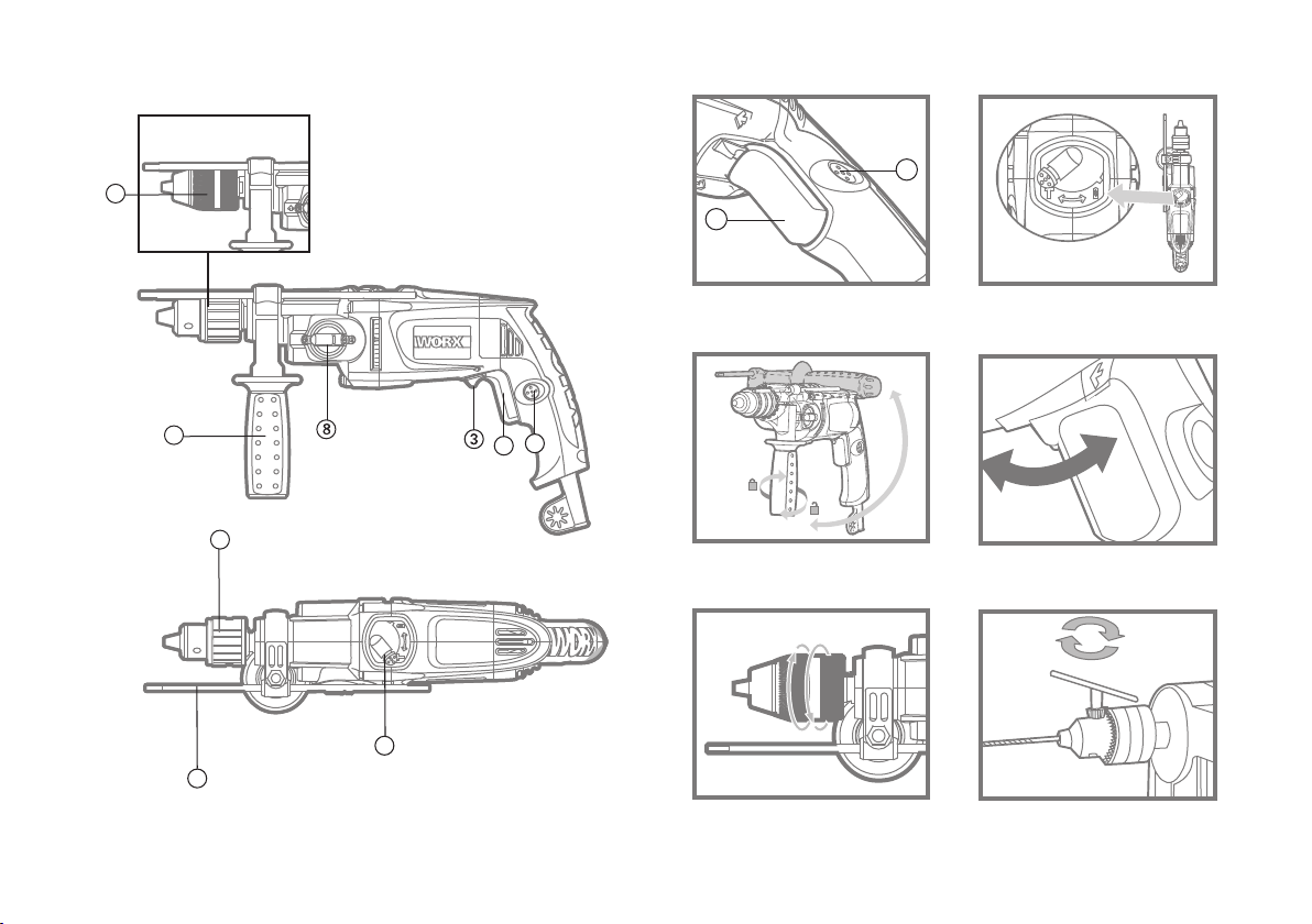
ON/OFF SWITCH
Depress to start and release to stop your tool.
SWITCH LOCK-ON BUTTON
Depress on/off switch (1) then lock on button (2) (See A), release
on/off switch first and lock-on button second. Your switch is now
locked on for continuous use. To switch off your tool just depress and
release the on/off switch.
FORWARD AND REVERSE ROTATION CONTROL
For drilling and screwdriving use forward rotation marked “ ”(lever
is moved to the left). Only use reverse rotation marked “ ”(lever is
moved to the right) to remove screws or release a jammed drill bit.
(See D)
Never change the direction of rotation when the tool is
rotating, wait until it has stopped.
AUXILIARY HANDLE
Slide the handle onto the drill and rotate to the desired working
position. To clamp the auxiliary handle rotates the handgrip clockwise.
To loosen the auxiliary handle rotate the hand grip anti-clockwise.
Always use the auxiliary handle (See C).
DEPTH STOP
Fit the drill bit or driver bit into the chuck. Loosen the depth stop by
rotating the handle grip anti-clockwise. Slide the depth stop until the
distance between the depth stop end and the drill/driver bit end is
equal to the depth of hole/screw you wish to make. Then clamp the
depth stop by rotating the handle clockwise.
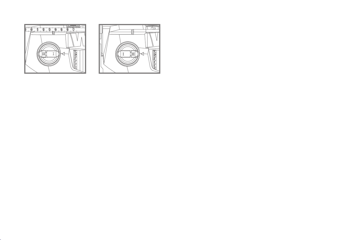
HAMMER OR DRILLING CONTROL
When drilling masonry and concrete choose the Hammer position
When drilling wood, metal, plastic and screwdriving choose the Drill
position. (See B)
INSERTING A TOOL INTO CHUCK
KEYLESS CHUCK (WU303.1)
To open the chuck jaws rotate the front section of the chuck while
holding the rear section. Insert the drill bit between the chuck jaws
and rotate the front section in the opposite direction while holding the
rear section. Ensure that the drill bit is in the center of the chuck jaws.
Finally, firmly rotate the two separate chuck sections in opposite
directions. Your drill bit is now locked in the chuck. (See Fig E)
KEY CHUCK (WU303)
Remove chuck key from key storage tab at base of drill handle, keep
pressing the spindle lock (3), the output ( principal) axis or spindle
will be locked, then place key into chuck, turn key anti-clockwise to
undo/loosen chuck, inset drill/tool and firmly tighten chuck by turning
key clockwise. Remove key and replace in storage tab at base of drill
handle (See Fig F).
5
6
7

9
GEAR BOX SWITCH
Choose position 1 for high torque/low speed range for large diameter
drill bits and screw driving. Choose position 2 for low torque/ High-
speed range for small diameter drill bits. If the gears do not engage
easily then rotate the chuck by hand to align the gears. Never change
the gears when the tool is rotating, wait until it has stopped.
Working hints for your drill
If your power tool becomes too hot. set the speed to maximum and
run no load for 2-3 minutes to cool the motor. Tungsten carbide drill
bits should always be used for concrete and masonry. When drilling
in metal, only use HSS drill bits in good condition. Always use a
magnetic bit holder when using short screwdriver bits.
Where possible use a pilot hole before drilling a large diameter hole.
Maintenance
Remove the plug from the socket before carrying out any
adjustment, servicing or maintenance.
Your power tool requires no additional lubrication or maintenance.
There are no user serviceable parts in your power tool. Never use
water or chemical cleaners to clean your power tool. Wipe clean with
a dry cloth. Always store your power tool in a dry place. Keep the
motor ventilation slots clean. Keep all working controls free of dust.
Occasionally you may see sparks through the ventilation slots. This
is normal and will not damage your power tool. If the supply cord is
damaged, it must be replaced by the manufacturer, its service agent
or similarly qualified persons in order to avoid a hazard.
8

10
Environmental protection
Waste electrical products should not be disposed of with
household waste. Please recycle where facilities exist. Check
with your local authorities or retailer for recycling advice.
Plug replacement
(UK & Ireland only)
If you need to replace the fitted plug then follow the instructions
below.
IMPORTANT
The wires in the mains lead are colored in accordance with the
following code:
BLUE =NEUTRAL BROWN = LIVE
As the colors of the wires in the mains lead of this appliance may not
correspond with the colored markings identifying the terminals in
your plug, proceed as follows. The wire which is colored blue must
be connected to the terminal which is marked with N. The wire which
is colored brown must be connected to the terminal which is marked
with L.
Note: If a moulded plug is fitted and has to be removed take great
care in disposing of the plug and severed cable, it must be destroyed
to prevent engaging into a socket.
Connect
Blue to N
(neutral)
Outer sleeve
firmly clamped
Cable grip
Brown L (live)
13 Amp fuse approved
to BS1362
WARNING!
Never connect live
or neutral wires to
the earth terminal
of the plug. Only
fit an approved
13ABS1363/A plug
and the correct
rated fuse.

11
EC DECLARATION OF
CONFORMITY
We,
POSITEC Germany GmbH
Theodor-Heuss-Ring 1-3
50668 Köln
Declare that the product,
Description WORX Impact drill
Type WU303 WU303.1
Function Boring holes in various materials
Complies with the following Directives,
EC Machinery Directive 2006/42/EC
EC Low Voltage Directive 2006/95/EC
EC Electromagnetic Compatibility Directive 2004/108/EC
Standards conform to
EN 55014-1 EN 55014-2 EN 61000-3-2
EN 61000-3-3 EN 60745-1 EN 60745-2-1
The person authorized to compile the technical file,
Name Russell Nicholson
Address Positec Power Tools (Europe) Ltd, PO Box 152, Leeds,
LS10 9DS, UK
2011/01/21
Jacky Zhou
POSITEC Quality Manager
•
•
•

12
TECHNISCHE DATEN
Spannung 220-240V~50/60Hz
Nennaufnahmeleistung 900W
Leerlaufdrehzahl
Gang 1 0-1,300/min
Gang 2 0-2,700/min
Nennschlagzahl
Gang 1 0-20800bpm
Gang 2 0-43200bpm
Schutzisoliert / II
Max. Spannweite des Bohrfutters. 13mm
Max. Bohrleistung
Mauerwerk 20mm
Stahl 13mm
Holz 40mm
Gewicht 2.45kg
LÄRMPEGEL UND VIBRATIONEN
Gewichteter Schalldruck 94dB(A)
Gewichtete Schallleistung 105dB(A)
KpA & KwA 3dB(A)
Tragen Sie bei einem Schalldruck über einen Gehörschutz 80dB(A)
1
2
3
4
5
6
7
8
9
BEDIENTEILE
EIN/AUS-SCHALTER
EINSCHALTSPERRE
VORWÄRTS-RÜCKWÄRTSLAUF-REGELUNG
BOHRFUTTER
HANDGRIFF VORNE
TIEFENANSCHLAG
SCHLAGBOHREN-BOHREN-REGELUNG
SCHALTKASTENSCHALTER
SCHNELLSPANNBOHRFUTTER NUR(WU303.1)
* Abgebildetes oder beschriebenes Zubehör gehört teilweise nicht
zum Lieferumfan.
•
•
•
•
•
•
•
•
•
•
•
•

13
INFORMATIONEN ÜBER
VIBRATIONEN
Vibrationsgesamtmesswertermittlung gemäß EN 60745:
Schlagbohren in Beton Vibrationsemissionswert ahID = 23.8m/s2
Unsicherheit K = 1.5m/s²
Bohren in Metall Vibrationsemissionswert ahD = 4.7m/s2
Unsicherheit K = 1.5m/s²
WARNUNG: Der Vibrationsemissionswert während des
tatsächlichen Gebrauchs des Elektrowerkzeugs kann vom
angegebenenWert abweichen, je nachdem, wie das Werkzeug gemäß
folgender Beispiele und anderweitiger Verwendungsmöglichkeiten
eingesetzt wird:
Wie das Werkzeug verwendet wird und Materialen geschnitten oder
angebohrt werden.
Das Werkzeug ist in gutem Zustand und gut gepflegt
Verwendung des richtigen Zubehörs für das Werkzeug und
Gewährleistung seiner Schärfe und seines guten Zustands.
Die Festigkeit der Handgriffe und ob Antivibrationszubehör verwendet
wird.
Und ob das verwendeteWerkzeug dem Design und diesen
Anweisungen entsprechend verwendet wird.
Wird diesesWerkzeug nicht anemessen gehandhabt, kann es ein
Hand-Arm-Vibrationssyndrom erzeugen.
WARNUNG: Um genau zu sein, sollte ein Abschätzung des
Belastungsgrades aller Arbeitsabschnitte während tatsächlicher
Verwendung berücksichtigt werden, z.B. die Zeiten, wenn das
Werkzeug ausgeschaltet ist, und wenn es sich im Leerlauf befindet
und eigentlich nicht eingesetzt wird. Auf dieseWeise kann der
Belastungsgrad während der gesamten Arbeitszeit wesentlich
gemindert werden.
Minimieren Sie Ihr Risiko, dem Sie bei Vibrationen ausgesetzt sind.
Verwenden Sie IMMER scharfe Meissel, Bohrer und Sägeblätter.
Pflegen Sie dieses Werkzeug diesen Anweisungen entsprechend und
achten Sie auf eine gute Einfettung (wo erforderlich).
Bei regelmäßiger Verwendung diesesWerkzeugs sollten Sie in
Antivibrationszubehör investieren.
Vermeiden Sie den Einsatz vonWerkzeugen beiTemperaturen von
10ºC oder darunter.
Machen Sie einen Arbeitsplan, um die Verwendung von
hochvibrierenden Werkzeugen auf mehrereTage zu verteilen.
ZUBEHÖRTEILE
Bohrfutterschlüssel (WU303) 1
HANDGRIFF VORNE 1
Tiefenanschlag 1
Wir empfehlen Ihnen, sämtliche Zubehörteile beim selben Fach-
händler zu beziehen, bei dem Sie auch Ihr Elektrowerkzeug gekauft
haben. Verwenden Sie nur hochwertige Zubehörteile von namhaften
Herstellern. Die Güteklasse muss entsprechend der Anwendung
gewählt werden. Weitere Informationen finden Sie auf der Verpack-
ung der Zubehörteile. Auch Ihr Fachhändler berät Sie gerne.
•
•
•
•
•
•

14
1
2
3
4
5
6
7
8
9
10
11
ZUSÄTZLICHE
SICHERHEITSHINWEISE FÜR
IHRE SCHLAGBOHRMASCHINE
Ziehen Sie den Stecker aus der Steckdose, ehe Sie
Einstellungsänderungen, Reparatur- oder Wartungsarbeiten
durchführen.
Wickeln Sie das Verlängerungskabel von der Trommel, um eine
mögliche Überhitzung zu vermeiden.
Falls ein Verlängerungskabel erforderlich ist, verwenden Sie ein
funktionstüchtiges, zugelassenes Verlängerungskabel, das für die
Leistung des Werkzeugs ausreichend ist.
Kontrollieren Sie, ob die Netzspannung der auf dem Typenschild
angegebenen Spannung entspricht.
Das Werkzeug ist schutzisoliert. Dies bietet zusätzlichen Schutz vor
möglichen Kurzschlüssen im Werkzeug.
Prüfen Sie vor dem Arbeiten in Wänden und Decken den genauen
Verlauf von Stromkabeln oder Rohrleitungen.
Zugängliche Metallteile und Zubehörteile können bei längerem
Gebrauch sehr heiß werden.
Tragen Sie beim Arbeiten mit diesem Werkzeug eine Schutzbrille.
Tragen Sie Gehörschutz bei der Arbeit mit
Schlagbohrmaschinen. Lärmaussetzung kann Gehörverlust
verursachen.
Benutzen Sie den zusätzlichen Handgriff, der mit dem
Werkzeug geliefert wird. Kontrollverlust kann Personenschäden
zufolge haben.
Halten Sie das Werkzeug nur an den isolierten griffigen
Oberflächen, wenn Sie einen Einsatz durchführen, bei dem
Schneidwerkzeuge eventuell versteckte Kabel berühren
könnten. Berührung mit einem unter Strom stehenden Kabel
kann auch die Metallteile des Gerätes unter Strom setzen und dem
Bedienenden einen Stromschlag versetzen.
Benutzen Sie die Bohrmaschine niemals in der Nähe von Wasser.
Benutzen Sie die Bohrmaschine niemals als Schraubenzieher.
Halten Sie die Bohrmaschine beim Arbeiten stets fest im Griff.
Benutzen Sie immer die zusätzlichen Handgriffe, die zusammen
mit dem Gerät geliefert werden. Wenn Sie die Kontrolle über das
Werkzeug verlieren, kann es zu Verletzungen kommen.
12
13
14

15
SYMBOLE
Lesen Sie diese Bedienungsanleitung gut durch, bevor Sie die
Elektrowerkzeug benutzen.
Schutzisolation
Achtung – Bedienungsanleitung lesen!
Tragen Sie Gehörschutz, Wenn Sie die Elektrowerkzeug
benutzen.
Beim Arbeiten mit der Elektrowerkzeug, tragen Sie eine
Schutzbrille.
Tragen Sie eine Staubschutzmaske
Innerhalb der EU weist dieses Symbol darauf hin, dass dieses
Produkt nicht über den Hausmüll entsorgt werden darf.
Altgeräte enthalten wertvolle recyclingfähige Materialien, die
einer Wiederverwertung zugeführt werden sollten und um
der Umwelt bzw. der menschlichen Gesundheit nicht durch
unkontrollierte Müllbeseitigung zu schaden. Bitte entsorgen
Sie Altgeräte deshalb über geeignete Sammelsysteme oder
senden Sie das Gerät zur Entsorgung an die Stelle, bei der Sie
es gekauft haben. Diese wird dann das Gerät der stofflichen
Verwertung zuführen.
1
2
3
HINWEISE ZUM BETRIEB
Hinweis: Lesen Sie das Handbuch vor Inbetriebnahme des
Werkzeuges sorgfältig durch.
Bestimmungsgemäßer Gebrauch
Das Gerät ist bestimmt zum Schlagbohren in Ziegel, Beton und
Gestein, sowie zum Bohren in Holz, Metall, Keramik und Kunststoff.
EIN/AUS-SCHALTER
Drücken Sie, um das Werkzeug zu starten und lassen Sie los, um es
abzuschalten.
EINSCHALTSPERRE
Drücken Sie den An/Aus-Schalter (1) und dann die Einschaltsperre
(2) (siehe A). Lassen Sie zuerst den An/Aus-Schalter und dann die
Einschaltsperre los. Ihr Schalter ist nun im Dauerbetrieb eingerastet.
Um Ihr Werkzeug abzuschalten, drücken Sie einfach den An/Aus-
Schalter und lassen Sie ihn wieder los.
VORWÄRTS-RÜCKWÄRTSLAUF-REGELUNG
Zum Bohren und Schrauben nutzen Sie den Vorwärtslauf, dieser
ist markiert als “ ”(Hebel ist zur linken Seite umgelegt). Nutzen
Sie die Rücklauffunktion, markiert als “ ”(Hebel ist zur rechten
Seite umgelegt) nur, um Schrauben herauszudrehen oder um
eingeklemmte Bohrer herauszuholen. (siehe D).
Wechseln Sie die Drehrichtung niemals, während der Bohrer
läuft. Warten Sie, bis der Bohrer ausgelaufen ist.

16
HANDGRIFF VORNE
Schieben Sie den Handgriff auf den Bohrerhals und drehen Sie ihn in
die gewünschte Position. Um den Seitengriff festzuklemmen, drehen
Sie den Handgriff gegen den Uhrzeigersinn. Um den Seitengriff zu
lösen, drehen Sie den Handgriff im Uhrzeigersinn. Benutzen Sie
immer den Hilfsgriff (siehe C).
TIEFENANSCHLAG
Passen Sie den Bohrer oder Schrauberbit in das Bohrfutter ein.
Lösen Sie den Tiefenanschlag, indem Sie den Handgriff gegen den
Uhrzeigersinn drehen.
Verschieben Sie den Tiefenanschlag, bis die Entfernung zwischen
Tiefenanschlag und Bohrer/ Schrauberbit der gewünschten Bohrtiefe
entspricht. Klemmen Sie dann den Tiefenanschlag fest, indem Sie
den Handgriff gegen den Uhrzeigersinn drehen.
BOHREN-SCHLAGBOHRERN-REGELUNG
Wenn Sie Mauerwerk oder Beton bohren, wählen Sie die
Schlagbohrfunktion. Wenn Sie Holz, Metall oder Kunststoff
bohren bzw. schrauben wollen, wählen Sie die Bohrfunktion (siehe
B).
EINFÜGEN EINES WERKZEUGS IM SPANNFUTTER
SPANNFUTTER OHNE SCHLÜSSEL (WU303.1)
Um das Bohrfutter zu öffnen, drehen Sie den vorderen Teil des
Bohrfutters, während Sie gleichzeitig den hineren Teil festhalten.
Stecken Sie den Bohrer in das Bohrfutter, halten Sie den hinteren
Teil des Bohrfutters fest und drehen Sie den vorderen Teil in
entgegengesetzter Richtung. Achten Sie darauf, dass der Bohrer in
der Mitte des Bohrfutters sitzt. Zuletzt drehen Sie beide Teile des
4
5
6
7
Bohrfutters fest in entgegengesetzten Richtungen. Der Bohrer sitzt
nun fest im Bohrfutter. (Siehe E)
SPANNFUTTER MIT SCHLÜSSEL (WU303)
Entfernen Sie den Spannfutterschlüssel von der Schlüsselaufnahme
an der Basis des Bohrgriffs, halten Sie den Spindelarretierung (3)
gedrückt, die Ausgangs-(Haupt)achse oder -spindel verriegelt
sich, stecken Sie den Schlüssel in das Spannfutter, drehen Sie den
Schlüssel entgegen den Uhrzeigersinn, um das Spannfutter zu
befreien/lösen, fügen Sie den Bohrer/das Werkzeug ein und ziehen
Sie das Spannfutter durch Drehen des Schlüssels im Uhrzeigersinn
fest an. Ziehen Sie den Schlüssel ab und bringen Sie ihn wieder in der
Schlüsselaufnahme an der Basis des Bohrgriffs unter (Siehe F).
SCHALTKASTENSCHALTER
Position I(Siehe G) eignet sich für Arbeiten mit niedriger Drehzahl
und hohem Drehmoment – für Bits mit großem Durchmesser
und zum Anziehen von Schrauben. Position II (Siehe H) ist für
Arbeiten gedacht, die mit hoher Geschwindigkeit und mit niedrigem
Drehmoment ausgeführt werden – für Bits mit kleinem Durchmesser.
Falls sich die Gänge nicht leicht umstellen lassen sollten, drehen Sie
das Bohrfutter etwas mit der Hand. Wechseln Sie niemals Gänge
bei laufendem Werkzeug. Warten Sie immer, bis das Gerät komplett
gestoppt ist.
8

17
ARBEITSHINWEISE FÜR IHRE
SCHLAGBOHRMASCHINE
Wenn das Gerät zu heiß wird, lassen Sie ihn 2-3 Minuten im Leerlauf
laufen, um den Motor abzukühlen.
Wolfram-Karbid Bohrer sollten immer für Beton und Mauerwerk
benutzt werden.
Wenn Sie in Metall bohren, verwenden Sie nur HSS-Bohrer in gutem
Zustand.
Immer einen magnetischen Bithalter verwenden, wenn Sie kurze
Schraubendreherbits verwenden.
Wenn möglich, immer ein Loch vorbohren, wenn Sie große
Durchmesser bohren möchten.
WARTUNG
Ihr Werkzeug benötigt keine zusätzliche Schmierung oder Wartung.
Es enthält keine Teile, die Sie warten müssen. Reinigen Sie Ihr
Werkzeug niemals mit Wasser oder chemischen Reinigungsmitteln.
Wischen Sie es mit einem trockenen Tuch sauber. Lagern Sie
Ihr Werkzeug immer an einem trockenen Platz. Halten Sie die
Lüftungsschlitze sauber. Gelegentlich sind durch die Lüftungsschlitze
hindurch Funken zu sehen. Dies ist normal und wird Ihr Werkzeug
nicht beschädigen.
UMWELTSCHUTZ
Elektroprodukte dürfen nicht mit dem normalen Haushaltsmüll
entsorgt werden, sondern sollten nach Möglichkeit zu einer
Recyclingstelle gebracht werden. Ihre zuständigen Behörden
oder Ihr Fachhändler geben Ihnen hierzu gerne Auskunft.

18
EC KONFORMITÄTSERKLÄRUNG
Wir,
POSITEC Germany GmbH
Theodor-Heuss-Ring 1-3
50668 Köln
Erklären hiermit, dass unser Produkt
Beschreibung WORX Schlagbohrer
Typ WU303 WU303.1
Funktion Bohren von Löchern in verschiedenen Materialien
Den Bestimmungen der folgenden Richtlinien entspricht:
EC Maschinenrichtlinie 2006/42/EC
EC Niederspannungsrichtlinie 2006/95/EC
EC EMV-Richtlinie 2004/108/EC
Normen:
EN 55014-1 EN 55014-2 EN 61000-3-2
EN 61000-3-3 EN 60745-1 EN 60745-2-1
Zur Kompilierung der technischen Datei ermächtigte Person
Name Russell Nicholson
Adresse Positec Power Tools (Europe) Ltd, PO Box 152, Leeds,
LS10 9DS, UK
2011/01/21
Jacky Zhou
POSITEC Qualitätsleiter
•
•
•

19
Caractéristiques techniques
Tension nominale- fréquence 220-240V~50/60Hz
Puissance 900W
Vitesse à vide
vitesse 1 0-1,300/min
vitesse 2 0-2,700/min
Cadence de frappe nominale
vitesse 1 0-20800bpm
vitesse 2 0-43200bpm
Double isolation / II
Capacité max. du mandrin 13mm
Capacité max de perçage
béton 20mm
acier 13mm
bois 40mm
Poids de la machine 2.45kg
Données sur le bruit et les vibrations
Niveau de pression acoustique 94dB(A)
Niveau de puissance acoustique 105dB(A)
KpA & KwA 3dB(A)
Porter des protections auditives lorsque la pression sonore est
supérieure à 80dB(A)
1
2
3
4
5
6
7
8
9
Liste des composants
Interrupteur
Interrupteur avec dispositif de verrouillage
Commande de rotation avant et inversee
Mandrin
Poignée auxiliaire
Butée de profondeur
Commande de marteau ou de perceuse
Commutateur du boîtier de vitesse
Mandrin auto-serrant(WU303.1)
* Les accessoires reproduits ou décrits ne sont pas tous compris
avec le modèle standard livré.
•
•
•
•
•
•
•
•
•
•
•
•

20
Informations relatives aux
vibrations
Valeurs totales de vibrations déterminées selon l’EN 60745:
Perçage par percussion dans
le béton:
Valeur d'émission de vibrations ahID = 23.8m/s2
Incertitude K = 1.5m/s²
Perçage dans le métal: Valeur d'émission de vibrations ahD = 4.7m/s2
Incertitude K = 1.5m/s²
Avertissement: La valeur d’émission de vibrations pendant
l’utilisation réelle de l’outil électrique peut différer de la valeur déclarée
selon la façon dont l’outil est utilisé, selon les exemples suivants et
d’autres variations sur la façon dont l’outil est utilisé:
Comment l’outil est utilisé et quels matériaux sont coupés ou percés.
L’outil est en bon état et bien entretenu.
L’utilisation du bon accessoire pour l’outil et l’assurance qu’il est affuté
et en bon état.
Le serrage du grip sur les poignées et le cas échéant les accessoires
anti-vibrations utilisés.
Et l’outil est utilisé comme prévu dans sa conception et dans les
présentes instructions.
Cet outil peut causer un syndrome de vibration du bras et de la
main s’il n’est pas correctement géré.
Avertissement: Pour être précise, une évaluation du niveau
d’exposition en conditions réelles d’utilisation doit également tenir
compte de toutes les parties du cycle d’utilisation telles que les
moments où l’outil est éteint, et ceux où il fonctionne au ralenti
mais ne réalise pas réellement de tâche. Ceci peut réduire de façon
significative le niveau d’exposition et la période de fonctionnement
totale.
Aider à minimiser le risque d’exposition aux vibrations.
UtilisezTOUJOURS des ciseaux, des forets et des lames affutés
Entretenez cet outil en accord avec les présentes instructions et
maintenez-le lubrifié (si approprié)
Si l’outil doit être utilisé régulièrement, alors investissez dans des
accessoires anti-vibrations.
Évitez d’utiliser des outils à des températures de 100C ou moins
Planifiez votre travail pour étaler toute utilisation d’outil à fortes
vibrations sur plusieurs jours.
Accessoires
Clef de mandrin (WU303) 1
Poignée auxiliaire 1
Butée de profondeur 1
Nous recommandons d’acheter tous les accessoires dans le magasin
où l’outil a été acheté. Utilisez des accessoires de bonne qualité et de
marque.
Choisissez les meules adaptées au travail à réaliser. Reportez vous
à l’emballage pour de plus amples informations. Le personnel du
magasin peut apporter aide et conseils.
•
•
•
•
•
•
Other manuals for WU303
1
This manual suits for next models
1
Table of contents
Languages:
Other Worx Professional Drill manuals

Worx Professional
Worx Professional WU181PT User manual

Worx Professional
Worx Professional WU189 User manual

Worx Professional
Worx Professional WU172 1 Series User manual

Worx Professional
Worx Professional WU303 User manual

Worx Professional
Worx Professional WU171 User manual

Worx Professional
Worx Professional WU362 User manual

Worx Professional
Worx Professional WU362 User manual

Worx Professional
Worx Professional WU100 User manual