Wow 774 User manual

USER MANUAL

USE AND MAINTENANCE MANUAL
2
We would like to thank you for choosing a WOW 774-775
scooter.
In order to maintain the scooter always in perfect status of
eciency, we recommend to read and follow carefully the
instructions contained herein.
In this manual you will nd some detailed information on
how to use and maintain your WOW 774-775.
So that the warranty conditions do not lapse, we invite you
to contact only WOW Authorized Workshops and ask for
original WOW spare parts. For all information regarding
your WOW 774-775 guarantee we recommend to read
carefully the warranty booklet. The updated version of this
Use and Maintenance Manual is always available on the
website: www.wowescooter.com.
Ask always for WOW Original Spare Parts. Only
purchasing WOW Original Spare Parts you will
receive a qualied technical assistance you will
appreciate for reliability, performance and a
constant safety along the time.

USE AND MAINTENANCE MANUAL
3
WOW! S.r.l. declines any responsibility for mistakes in which it
may have incurred in lling this manual and it reserves the right
to make any change required by its product development. WOW!
S.r.l. reserves the right to make technical and aesthetic, or other
modications without any further forewarning.
Version N1

USE AND MAINTENANCE MANUAL
4
1 Scooter identication and details pp. 5-7
2 Controls pp. 8-12
3 Use of scooter and main functions pp. 13-25
4 Lithium-ion batteries utilization warnings pp. 26-28
5 Driving safety pp 29-33
6 Checkup and maintenance pp. 34-44
7 Accessories utilization warnings p. 45

USE AND MAINTENANCE MANUAL
5
The vehicle identication number (VIN) or
frame number is located on the right side,
under the passenger footrest and on the
rear shock absorber (see picture in detail).
Check the reported VIN matches with the
present one in the vehicle registration
document and on the warranty card.
Enter your scooter’s VIN below.
Vehicle Identication Number
SCOOTER IDENTIFICATION AND DETAILS

USE AND MAINTENANCE MANUAL
6
1 Underseat compartment
2 Rear brake lever (774 Model) - Combined braking lever (775 Model)
3 Battery charging socket
4 USB charging port for Smartphone / Electronic Devices
5 Left passenger footrest
6 Side stand
7 Central stand
8 Rear taillight and direction indicator
9 Left battery
SCOOTER IDENTIFICATION AND DETAILS

USE AND MAINTENANCE MANUAL
7
10 Front brake lever
11 Front headlight
12 Front brake disc
13 Ignition lock
14 Bag hook
15 Right passenger footrest
16 Right battery
17 Rear brake disc
SCOOTER IDENTIFICATION AND DETAILS

USE AND MAINTENANCE MANUAL
8
Remote control – Scooter keys
The scooter is supplied with two copies of a remote control key which serves as:
• keyless start switch
• underseat compartment opening
Keep the copy of the key separately.
- Ignition scooter’s button (1)
Once pressed for at least 3 seconds you will hear a noise beep and the scooter will
turn on by its ignition lock.
- Vehicle turn o key (2)
Once the vehicle is turned o, the immobilizer alarm will go o (in case of vehicle
displacement such a system will emit a beep sequence).
- Passenger seat opening button for batteries removal (3)
CONTROLS
Press down to removePress down to remove
the mechanical keythe mechanical key
Insert the keyInsert the key
by sliding the apby sliding the ap
Mechanically unlockMechanically unlock
the rear seatthe rear seat
- Into the remote control is included a “mechanical” key (4) - to
use in case remote control / vehicle batteries are at.
- The mechanical key must be inserted in the ignition lock by
sliding the specic ap shown in the picture. Once the front
seat has been unlocked, it can be used to mechanically unlock
the rear seat through a dedicated lock placed between the two
seats.
Please Note: The mechanical key has to be used also in case of
absence of on-board batteries to open the compartment under
the seat and to insert the batteries into their housing when the
rear seat is closed.

USE AND MAINTENANCE MANUAL
9
CONTROLS
Dashboard

USE AND MAINTENANCE MANUAL
10
1 Odometer It indicates total kilometers traveled.
2 Battery indicator /charging status It indicates battery charge / vehicle range (SOC) percentage.
E = this map is more oriented towards battery energy saving with a good balance among maximum spe-
ed, acceleration and power consumption.
3 Map indicator in use C = this map provides, always looking for a suitable battery power saving, a strong acceleration at the
start. Mainly suited to urban paths.
S = this map provides the best performance during acceleration and the maximum speed.
4 Left direction indicator It indicates that left direction indicator is working.
5 High beams It indicates that high beams are on.
6 Battery recharging It indicates the vehicle batteries are currently on charge.
7 Parking mode Available only with the Sharing version.
8 Vehicle READY status It indicates that vehicle is on and ready for departure; by turning the throttle handle, the rear wheel will come
in function.
9 Reverse gear It indicates the “reverse gear” button on the left handlebar is pushed; by turning the throttle grip the
vehicle will reverse.
10 Vehicle default Proceed cautiously and carry the vehicle to a service network.
11 Dipped headlights It indicates that dipped headlights are on.
12 Right direction indicator It indicates that right direction indicator is working.
13 Engine power request indicator It indicates the required energy amount depending on our riding habit.
14 External temperature indicator It indicates the external temperature.
15 Speed indicator / Speedometer It indicates the current speed expressed by Km/h.
16 Odometer It indicates the trip distance covered. It can be reset by the button positioned on the right handlebar.
17 Speedometer measurement unit It indicates the unit of measurement for speed and distance traveled.
18 Failure code indicator Depending on which code has shown, it indicates the kind of vehicle failure (Call for WOW! Assistance).
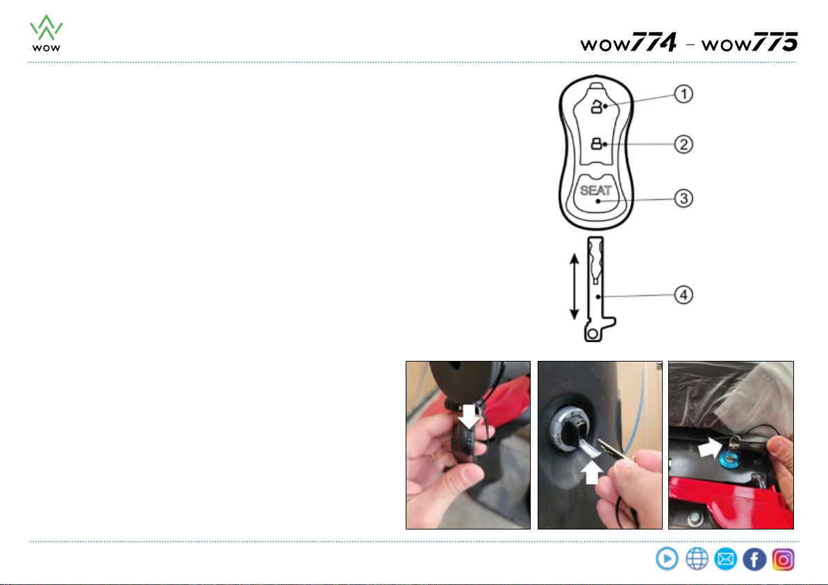
CONTROLS

USE AND MAINTENANCE MANUAL
11
CONTROLS
Funzioni di Controllo
Ignition Lock
The respective function positions are as follows:
OFF: the vehicle is o, lights are o and if you turn the throttle grip the scooter
doesn’t move (Figure 1).
ON: After pressing the “open padlock” button on the remote control, the
scooter and the lights can work (Figure 2).
LOCK: By turning without pressing the ignition switch on LOCK position, the
driver’s seat opens.
By switching the ignition switch on LOCK position and pressing the turning
part, the mechanical steering lock is activated.
The engine and lights cannot still run (Figure 3).
Beware
Always lock the steering when the scooter is parked to avoid unauthorized
use.
Beware
After the locking, try to gently turn the handlebar to make sure the steering
is actually locked.
Always unlock the steering before letting the vehicle o the stand.
The ignition switch automatically blocks in few seconds after it has been set
on OFF position. For security, by pressing the“padlock closed “ button on the
remote control, the lock blocks instantly.
1
2
3

USE AND MAINTENANCE MANUAL
12
CONTROLS
1 High beam / dipped headlight switch
2 Direction indicators button
3 Horn button
4 Reverse gear activation button
5 Vehicle ON / OFF switch (in case of danger as an emergency shutdown of the vehicle)
6 Engine map selector
7 Trip odometer reset button
8 Electromagnetic brake button allowing energy recharge

USE AND MAINTENANCE MANUAL
13
USE OF SCOOTER AND MAIN FUNCTIONS
Underseat Compartment Opening
The vehicle is equipped with an undersaddle compartment. To open the
rider seat (for reach the compartment) turn the ignition switch anticlockwise
towards the word LOCK without pressing (after pressing the “open padlock”
button on the remote control).
Beware
Maximum load allowed is 10 kg.
Make sure to close the seat correctly before using the scooter.

USE AND MAINTENANCE MANUAL
14
Bag hook
The scooter is equipped with a bag hook for small light
luggage carriage.
In order to use it, hang the bag handle on the dedicated
hook (2).
Beware
Maximum load allowed is 3 kg.
USE OF SCOOTER AND MAIN FUNCTIONS
5 V socket
The scooter is equipped with a 5 V socket for Smartphone
charging by a USB port (1).
• Insert the plug of the battery charger into the dedicated
USB port after removing the protection cap.
Beware
• In case of non-use remember to apply the dedicated plug
to the socket.
• Read carefully the charging instructions and technical
specications of your phone before insert the charging
cable into its port, so as not to damage it. Any damage
caused to the battery charger is not covered from
guarantee.

USE AND MAINTENANCE MANUAL
15
USE OF SCOOTER AND MAIN FUNCTIONS
Central stand
To put the scooter on central stand, by doing lever with one
foot on the stand, move the scooter holding the passenger
handle with the right hand while with the left hand keep
the handlebar, turning it to the left.
Beware
• To prevent accidents make sure the central stand is fully
retracted before departure.
• Make sure that the stand spring is working ne, to prevent
the central stand from lowering while driving, causing
accidents.

USE AND MAINTENANCE MANUAL
16
Side stand
Use side stand on rm and at ground only for short stops.
How to use it
• Turn o the scooter and get down of it.
• Extend side stand and rest the scooter on it.
• Turn completely the handlebar to the left and make sure the
scooter remains stable.
• When the side stand is pulled out the word READY won’t appear on
the dashboard and the scooter cannot move forward.
(see indications and instructions on the dashboard at page 9).
Beware
In order to prevent accidental bumps from dropping your scooter,
do not leave it on side stand on transit areas.
USE OF SCOOTER AND MAIN FUNCTIONS
Side stand
open
Retracted
Side stand

USE AND MAINTENANCE MANUAL
17
Passenger footrest
The scooter is equipped with retractable rear footrests
for a passenger.
To extract the passenger footrests press them inwards.
If you are traveling without a passenger, press the
footrests towards their housings until you hear a lock
click to keep them in an idle position.
USE OF SCOOTER AND MAIN FUNCTIONS

USE AND MAINTENANCE MANUAL
18
START-UP
On the remote control press the “open padlock” button (1) by turning
clockwise the ignition switch to “ON”.
To proceed with the scooter advancement throttle gently.
Beware
Before ignition, put always the scooter on central stand.
USE OF THE VEHICLE AND MAIN FUNCTIONS

USE AND MAINTENANCE MANUAL
19
Increase the speed smoothly
To put the scooter in motion, release brake lever and turn the
throttle grip slightly.
Beware
In order to keep scooter control ,increase speed gradually.
The speed is regulated by the throttle control.
Turn (1) The speed increases
• At start or approaching an uphill road, turn the grip gradually
to increase the power delivered from the engine.
Turn back (2) The speed decreases
• In case of braking or emergency, the grip turn back must be
carried out as much quickly as possible.
Drive carefully
Before taking the road switch on the direction indicators and
check for the arrival of no other vehicles.
USE OF THE VEHICLE AND MAIN FUNCTIONS

USE AND MAINTENANCE MANUAL
20
Brake management
For scooter best control operate the levers brake
gradually, at rst slightly then gradually more intensely,
depending on need. While braking, brake light comes
on to warn following vehicles.
Beware
Using only one brake can make the scooter slip. Always
use both brakes.
Avoid hard braking or sudden swerves
If abrutly used, brakes can cause a wheel block and lead
to a dangerous situation. Abrupt braking and sudden
swerving can cause slipping.
Make attention on wet roads
Grip on wet road is less than on a dry one and the
braking distance increases. Decrease the speed and pay
a close attention.
WOW 775 model is equipped with a combined braking
system. Left lever acts on front brake while the right
lever acts on both brakes (front and rear).
WOW775 COMBINED BRAKING SYSTEM
USE OF SCOOTER AND MAIN FUNCTIONS
REAR BRAKE FRONT BRAKE
This manual suits for next models
1
Table of contents