WRIGHT SIDEKICK EZ FRAME User manual

SIDEKICK® EZ FRAME
External Fixator System
SURGICAL TECHNIQUE
™

1
Introduction
Intended Use
Device Description
Surgical Technique
Preoperative Planning
Surgical Procedure
System Compatibility
Explant Information
Postoperative Care
Catalog Information
Chapter 1 2
2
Chapter 2 3
Chapter 3 4
4
4
Chapter 4 12
Chapter 5 13
Chapter 6 14
Chapter 7 15
Contents
Proper surgical procedures and techniques are the responsibility of the medical
professional. The following guidelines are furnished for information purposes only.
Each surgeon must evaluate the appropriateness of the procedures based on his or her
personal medical training and experience. Prior to use of the system, the surgeon should
refer to the product package insert for complete warnings, precautions, indications,
contraindications and adverse eects. Package inserts are also available by contacting
the manufacturer. Contact information can be found on the back of this surgical
technique and the package insert is available on the website listed.
For information on product availability in your area, please contact your local sales
representative.

2
Introduction
Chapter 1 Introduction
The SIDEKICK® EZ FRAME™ External Fixation System utilizes transosseous thin
wires and is based on the concepts of minimally invasive external fixation.
The system simplifies frame application when compared to traditional ring
fixators by eliminating the need for pins and wires to be placed into the tibia.
A boot is stabilized on the distal leg (tibia) and further stabilized to a distal ring
about the foot with carbon fiber reinforced composite rods that are connected
to the boot and ring respectively. Thin wires are placed into the foot to address
indications, while a frame-boot combination provides stability and support.
1
chapter
Intended Use
Indications for Use
» Triple Arthrodesis
» Isolated Rearfoot Arthrodesis
» Midfoot Arthrodesis
» Comminuted Trauma
» Diabetic Charcot Reconstruction
» Most foot pathology not requiring fixation above the ankle
Contraindications
» Talo-tibial or tibio-calcaneal arthrodesis
» Any pathology requiring absolute rigidity at or above the ankle
» Mentally unt patients
» Poorly vascularized patients
Prior to use of the system, the surgeon should refer to the product package
insert for complete warnings, precautions, indications, contraindications
and adverse effects. Package inserts are also available by contacting the
manufacturer. Contact information can be found on the back of this surgical
technique and the package insert is available on the website listed.

3
Device
Description
Chapter 2 Design Description
The SIDEKICK® EZ FRAME™ was designed to address the need for a simplied
approach to external xation. The system allows for the management of diabetic
Charcot reconstruction, triple arthrodesis, fusion of the midfoot and rearfoot,
challenging comminuted trauma, and most foot pathology not requiring xation
above the ankle. It is a viable tool for ooading and/or immobilizing wounds
associated with diabetic Charcot disease.
The system features transosseous thin wire xation, taking advantage of the
proven benets of minimally invasive external xator concepts. Bone segments
are easily and eectively manipulated for the purposes of midfoot and rearfoot
joint arthrodesis and for fusion of midfoot and rearfoot osteotomies. As with
other external xators, the frame may be applied with or without adjunct internal
xation.
By utilizing a unique combination of total contact casting concepts for the tibia
and thin wire xation in the foot, tibial wires or pins are not needed. By requiring
no pins or wires in the tibia, the SIDEKICK® EZ FRAME™ eliminates complications
associated with tibial xation elements and the time it takes to place these pins
and wires. The tibial boot portion of the frame helps facilitate positioning and
centering of the leg and foot, and the rocker plate helps to align the foot in a
neutral position. This simplies frame application compared to traditional circular
frames.
A rocker-bottom sole and rocker plate is attached to the foot ring. This rocker
plate features a cushioned surface insole upon which the foot can rest during
the healing process after the surgery. This insole (foot pad) may be modied
to accommodate compromised soft tissue as needed, by cutting it to relieve
pressure on compromised soft tissue. The position of the rocker plate can be
adjusted using optional spacers so that the foot is suspended, with no contact or
weight on the plantar surface of the foot. This can be particularly useful following
a ap or skin grafting procedure associated with diabetic Charcot reconstruction.
Spacers are available in two (2) thicknesses (5mm and 10mm).
The sterile boot liner allows for a custom tibial t and is designed to enhance
patient comfort.
The SIDEKICK® EZ FRAME™ is available in Standard and Large size kits.
The SIDEKICK® FREEDOM™ Circular Instrument Kit (RNRCKIT1) should be used
with the SIDEKICK® EZ FRAME™ System.
Replacement Boot Liners (Standard and Large), rocker-bottom soles, and foot
pads are available. The SIDEKICK® EZ FRAME™, and all frame components
(excluding instruments) are intended for single-use only.
2
chapter

4 Chapter 3 Surgical Technique
Preoperative Planning
The proper size xator should be ordered after considering patient anatomy.
Prior to surgery, the surgeon should consider the following while planning:
» Diameter of the distal leg
» Foot width and length
» Tibial length
Surgical Procedure
Example Procedure for Triple Arthrodesis
The leg should be prepared to above the knee and wrapped. Cast padding or
Kerlix with an Ace Bandage may be used to prepare the leg as shown.
After the completion of triple arthrodesis with provisional K-wire or screw
xation (surgeon’s preference), closure of all wounds, and application of all drains
as indicated, the foot and leg are placed within the SIDEKICK® EZ FRAME™ Fixator.
The foot should be placed in the center of the rocker plate, and the calf placed
within the boot. The insole may be placed between the foot and the rocker plate.
Surgical
Technique 3
chapter

5Chapter 3 Surgical Technique
Once adjustments are made to best t patient anatomy, the bolts should
be tightened with the 10mm wrench, locking the frame/boot position.
Subsequently, the surgeon is ready to insert the 2mm Titanium Nitride (TiN)
Tip Wires (#EF002400) across the foot to eventually achieve transosseous
compression of the arthrodesis sites. The 2mm Titanium Nitride (TiN) Tip Wires
(#EF002450) with olive and SIDEKICK® FREEDOM™ 1.8mm wires (#RR18400 and
#RR180400) are also available for use with the system.
When placing transosseous wires, they can be inserted directly through the skin
in a percutaneous manner. When using an olive (stopper) wire, a small 3mm
incision is made in the skin to allow the olive to rest directly against the bone.
Wires are inserted under power, and it is recommended to use a start/stop
technique to minimize potential thermal damage. Once the wire is through both
cortices, the wire can be tapped through the skin on the opposite side manually,
or advanced using the oscillating feature of the hand-held power equipment.
Tapping the wire manually or oscillating the wire may help prevent “wrapping”
soft tissue as the wire penetrates the soft tissue. When placing any percutaneous
xation, be mindful of anatomic safe zones. If a wire causes tension or tenting of
the skin, this tension should be released with a small incision. Utilization of the
uoroscope may be helpful in determining the exact anatomic position.
The boot position of the xator can be adjusted. Loosen the four vertical
adjustment locking bolts, the two carbon ber reinforced composite rod clamp
bolts, and the two carbon ber reinforced composite rod connector bolts using
the 10mm wrench (RR301090B SIDEKICK® SLOTTED WRENCH 10mm or the
RR3010 WRENCH 10mm) prior to adjusting the height of the boot assembly.
Once loosened, the boot assembly can be adjusted up or down by sliding the
boot assembly on the carbon ber reinforced rods.
Wrench 10mm
RR3010
SIDEKICK® Slotted Wrench 10mm
RR301090B

6 Chapter 3 Surgical Technique
Three essential 2mm TiN Tip Wires need to be placed in order to achieve the goal
of compressing fusion sites of the triple arthrodesis.
The rst wire crosses the calcaneus from medial to lateral avoiding the
neurovascular bundle. An olive wire may be used in this position to limit medial
migration of the foot on the frame after surgery.
Attach a post to the foot ring on either side of the foot, next to the wire that was
placed. Tighten the nuts on these posts to the ring using the 10mm wrench.
Attach the wire to the posts on either side using a wire bolt and a wire nut for
each end of the wire. The wire can be attached using the cannulation of the bolt,
or using the slot feature built into the nut.
Please note that the system features 6-hole male posts. Male and female posts
are also available with 1 through 4 holes. Select the aperture closest to the
location of the wire exiting the foot to determine placement of the wire bolt.
Use the longer 6-hole posts for wires further away from the foot plate, and use
shorter posts for wires that are closer to the foot plate. Calcaneal wires should
not be bent up or down when attaching them to the posts. Bending wires up
or down could result in elevating the heel away from the rocker bottom insole
or overly compressing it into the rocker bottom insole when the wires are
tensioned. Tighten the wire bolts and wire nuts using the 10mm wrench.
Wire attached using the
EZ FRAME™ wire bolt
Wire attached using the
EZ FRAME™ wire nut

7Chapter 3 Surgical Technique
The second wire crosses the talus from medial to lateral and should ideally be an
olive wire to limit lateral foot migration. If necessary, utilize the uoroscope to
ensure the correct placement of this 2mm wire across the talus.
Attach a post to the foot ring on either side of the foot, next to the wire that was
placed. Tighten the nut on the post to the ring using the 10mm wrench. Attach
the wire to the posts on either side using a wire bolt and a wire nut for each end
of the wire. Select the aperture closest to the location of the wire exiting the foot
to determine placement of the wire bolt. The ends of the talar wire should be
bent slightly down when attaching them to the male posts. This downward bend
will help provide better compression across the subtalar joint when tensioned.
Tighten the wire bolts and wire nuts using the 10mm wrench.
The third wire can be placed across the foot from either side. This wire can cross
the navicular and cuboid or alternatively cross from the medial cuneiform and
exit the cuboid. Once again, utilization of the uoroscope may be helpful in
determining the exact anatomic position.
Attach a post to the foot ring on either side of the foot next to the wire that was
placed. Tighten the nut on the post to the ring using the 10mm wrench. Attach
the wire to the posts on either side using a wire bolt and a wire nut for each end
of the wire. Select the aperture closest to the location of the wire exiting the
foot to determine placement of the wire bolt. Do not bend the wires up or down
when attaching them to the male posts. Tighten the wire bolts and wire nuts
using the 10mm wrench.
At least one additional transosseous 2mm wire is recommended to supplement
these three essential wires. It can be placed either across the calcaneus or
the midfoot. The exact location of this additional wire can be determined by
surgeon’s preference intraoperatively. This wire should be attached to the foot
ring via the same parameters as the rst three wires.

8 Chapter 3 Surgical Technique
Tensioner
RR3028
Once all wires are placed, the posts can be disconnected from their original
positions and realigned on the foot ring. This bends the 2mm wires in
anticipation of tensioning them to compress the arthrodesis sites. For a triple
arthrodesis the three essential wires, which have been described, are moved as
follows:
1. Move the two posts holding the transosseous calcaneal wire 1 or 2 holes
on the foot ring forward (towards the toes) and then reattach the posts
to the foot ring.
2. Move the two posts holding the transosseous talar wire 1 or 2 holes on
the foot ring back (towards the heel) and then reattach the posts to the
foot ring.
3. Move the two posts holding the transosseous midfoot wire 1 or 2 holes
on the foot ring back (towards the heel) and then reattach the posts to
the foot ring.
The fourth, additional wire should be moved in the same manner as the wires
described above. If the wire was placed in the calcaneus, the posts should be
moved forward and reattached. If the wire is placed in the midfoot, then the
posts should be moved back and reattached.
TENSIONING THE WIRES:
Tensioning of transosseous thin wires increases frame rigidity. By utilizing arched
wire concepts, bone segments can be manipulated to apply compression across
arthrodesis sites. When utilizing olive (stopper) wires, tension should be pulled
from the opposite side of the olive.
The calcaneal wire is the rst to be tensioned. Before tensioning this wire,
the posts should be rmly tightened to the footplate using the 10mm wrench.
The wire bolts and wire nuts on one side of the 2mm wire need to be rmly
tightened next. With the olive (stopper) wires, it should specically be noted that
the wire nut or post on the same side as the olive needs to be tightened rst.
Once the wire nut on one side of the foot has been rmly tightened, the
tensioner (RR3028 TENSIONER) is applied over the wire on the opposite side of
the foot, and moved down to contact the wire bolt.

9Chapter 3 Surgical Technique
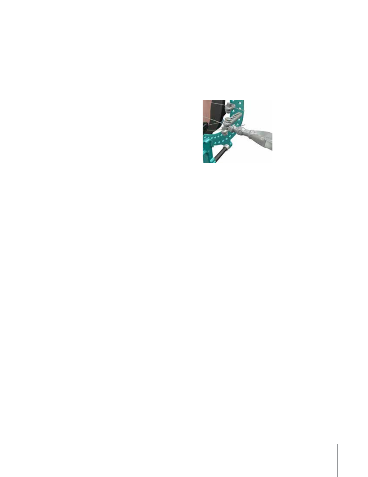
Tension is the applied to the wire by squeezing the tensioner handles. The wire
should be pulled from 70kg to 110kg, and this measure is taken by reading
where the force markings line up with the housing of the tensioner.
The tensioner should be held in place, maintaining tension, until the second
wire nut is tightened to the wire bolt. This will lock the wire under tension.
The tensioning device is then released. Tensioning the calcaneus wire stabilizes
the calcaneus while pushing it forward and compressing the posterior facet of
the calcaneus against the talus.
Next, the talar wire will be tensioned. Before tensioning this wire, the posts
should be rmly tightened to the foot ring using the 10mm wrench. The wire
bolts and wire nuts on one side of the 2mm wire need to be rmly tightened
next. With the olive (stopper) wires it should specically be noted that the
wire nut on the same side of the foot as the olive needs to be the one which is
tightened rst.
Once the wire nut or post on one side of the foot has been rmly tightened,
the tensioner is applied over the wire on the opposite side of the foot, and
moved down to contact the wire bolt. Tension is applied to the wire by squeezing
the tensioner handles. The wire should be pulled from 70kg to 110kg, and this
measure is taken by reading where the markings line up with the housing of
the tensioner. The tensioner should be held in place, maintaining tension, until
the second wire nut is tightened to the wire bolt. This will lock the wire under
tension. The tensioning device is then released. Tensioning the talar wire pushes
the talus backwards towards the posterior facet of the calcaneus, applying
compression from the opposite direction as the rst wire.
The midfoot wire is the last wire to be tensioned. Before tensioning this wire,
the posts should be rmly tightened to the footplate using the 10mm wrench.
The wire bolts and wire nuts on one side of the 2mm wire need to be rmly
tightened next. With the olive (stopper) wires it should specically be noted that
the wire nut on the same side of the foot as the olive needs to be tightened rst.
Once the wire nut on one side of the foot has been rmly tightened, the
tensioner is applied over the wire on the opposite side of the foot, and moved
down to contact the wire bolt. Tension is applied to the wire by squeezing the
tensioner handles. The wire should be pulled from 70kg to 110kg, and this
measure is taken by reading where the force markings line up with the housing
of the tensioner. The tensioner should be held in place, maintaining tension,
until the second wire nut is tightened to the wire bolt. This will lock the wire
under tension. The tensioning device is then released. Tensioning the midfoot
wire results in compression across the talaonavicular and calcaneocuboid joints.

10 Chapter 3 Surgical Technique
The fourth wire should be arched and tensioned in the same manner as the wires
described above. Once wires are properly tensioned, the surgeon should cut and
curl wires to prevent unintentional injury.
All nuts and points of tightening should be locked securely. Make sure skin is not
tenting at any of the wire sites. If it is, release it with a #11 blade. At this point,
a nal check should be made to ensure all connections are tight and secure.
After all wires/pins are placed, it is necessary to secure the boot portion of the
xator to the leg. The sterile liner should be wrapped around the lower leg, using
the Velcro® tabs to secure the liner in place. Care should be taken to not have
wrinkles or folds in the liner. These Velcro® tabs should align with the top of the
boot component.
The boot portion of the frame can be adjusted to dierent diameters to
accommodate diering patient anatomy. These adjustments are made by
adjusting the tabs at the back of the boot. The SIDEKICK® EZ FRAME™ features
three adjustable Velcro® straps.
The EZ FRAME™ system also features locking straps that may be used to
post-operatively replace standard Velcro® straps. To tighten the straps, release
the locking clamp by rotating the purple locking mechanism into a horizontal
position with the white key. Once tightened, close the clamp and rotate the key
and locking mechanism back into a vertical orientation.

11
Once the liner is tted and the boot portion of the frame is secured around the
leg, the liner can be customized to t the patient anatomy. After adjusting, each
strap should be pulled snugly and secured, ensuring proper t.
Safety seals are available to place over the Velcro® straps after nal adjustments.
These seals will not prevent adjustments made by patients, but will indicate if
any unauthorized adjustments are made.
The heel of the plate should be pressed down onto the rocker-bottom sole to
connect with the rocker plate as shown.
Optional spacers can be used to move the plate away from the plantar surface of
the foot. Spacers are available in two (2) thicknesses (5mm and 10mm).
Important Note: The locking optional locking straps, safety seals, and the rocker-
bottom sole are all available nonsterile. They should not be applied in the sterile
eld.
Chapter 3 Surgical Technique

12 Chapter 4 System Compatibility
4
chapter
System
Compatibility
The SIDEKICK® EZ FRAME™ is designed to accept SIDEKICK® FREEDOM™ Circular
System components. It is important to note that the SIDEKICK® EZ FRAME™
wires are 2mm in diameter. They are not compatible for use with the SIDEKICK®
FREEDOM™ Circular System wire xation bolts. The SIDEKICK® FREEDOM™
Circular System wire xation bolts will only accommodate 1.8mm wires.

13Chapter 5 Explant Information
5
chapter
Explant
Information
Frame removal can be achieved with the following steps
» Detach wires from the frame.
» Unfasten and loosen Velcro® boot straps from about the tibia.
» Remove the leg and foot from the frame.
» Remove wires from the foot. Cut the wire on one side of the foot, close to
the surface of the skin. Pull the wire from the other side, applying steady
force, until the wire is removed. Note: When removing an olive wire
(stopper wire), pull the wire from the same side as the olive.
» If the removal of the implant is required due to revision or failure of the
device, the surgeon should contact the manufacturer using the contact
information located on the back cover of this surgical technique to receive
instructions for returning the explanted device to the manufacturer for
investigation.

14 Chapter 6 Postoperative Care
6
chapter
Postoperative
Care
Postoperatively, the frame should be checked routinely to ensure that no frame
components have loosened. Any loosened components should be retightened.
If a wire has loosened or become unattached from the frame, it should be
retensioned, reattached (if necessary), and xation components should be
tightened.
In the event of wire breakage, the broken wire should be removed. A new wire
should be placed if needed to restore construct stability.
The boot liner can be replaced if necessary, as the surgeon sees t. Replacement
rocker-bottom soles and foot pads are also available if needed.
The surgeon must educate the patients on wire care and be diligent in watching
for any signs of pin irritation. Wire site care is per surgeon preference. Aggressive
wire site management, appropriate use of oral antibiotics, and a relatively low
threshold to remove a problematic wire should be considered to minimize the
risk of serious complication and ensure the desired outcome.

15Chapter 7 Catalog Information
Part Number Description
EF100000* EZ FRAME™ FIXATOR ASSEMBLY STD NON STERILE KIT
EF00KIT1 EZ FRAME™ INSTRUMENT KIT
EF00KITA EZ FRAME™ IMPLANT KIT
EF10000L* EZ FRAME™ FIXATOR ASSEMBLY LGE NON STERILE KIT
EF001500 EZ FRAME™ WIRE BOLT
EF001600 EZ FRAME™ WIRE NUT
EF001650 EZ FRAME™ POST 6HOLE
EF002000 EZ FRAME™ ROCKER PLATE
EF002400 EZ FRAME™ WIRE 2MM
EF002450 EZ FRAME™ OLIVE WIRE 2MM
EF002500 EZ FRAME™ SOLE
EF002550 EZ FRAME™ QUICK NUT
EF003005 EZ FRAME™ SPACER 5MM
EF003010 EZ FRAME™ SPACER 10MM
EF003700 EZ FRAME™ FOOT PAD
EF103750 EZ FRAME™ LINER STANDARD
EF103775 EZ FRAME™ LINER LARGE
EF190002 EZ FRAME™ LOCKING STRAPS
EF004180 EZ FRAME™ FOOT RING
EF1500PK EZ FRAME™ WIRE BOLT PK /12
EF1600PK EZ FRAME™ WIRE NUT PK /12
EF1650PK EZ FRAME™ POST 6HOLE PK/12
EF2400PK EZ FRAME™ TIN TIP WIRE 2MM PK / 6
EF2450PK EZ FRAME™ TIN TIP OLIVE WIRE 2MM 6 / PK
EF3005PK EZ FRAME™ SPACER 5MM 3/PK
EF3010PK EZ FRAME™ SPACER 10MM 3/PK
EF375000 EZ FRAME™ SECURITY SEAL 5 / PK
EF410160 EZ FRAME™ 160MM DORSAL 1/2 RING
RR3000 BOLT 30MM
RR3520180TN PIN 3X180X20 TIN
RR3535180TN PIN 3X180X35 TIN
RR4000 BOLT 40MM
RR2001CE ADAPTER
SIDEKICK® EZ FRAME™ Components
7
chapter
Catalog
Information
*Note: Primary components are packaged
with detailed Instructions for Use.

16
Part Number Description
RR0080TR THREADED ROD, 80 MM
RR0120TR THREADED ROD, 120 MM
RR0150TR THREADED ROD, 150 MM
RR0165TR THREADED ROD, 165 MM
RR0200TR THREADED ROD, 200 MM
RR0300TR THREADED ROD, 300 MM
RR0400TR THREADED ROD, 400 MM
RR1001 NUT, 10MM
RR100PL PLATE, 1 HOLE
RR1010 SQUARE NUT
RR10P MALE POST, 1 HOLE
RR10PF FEMALE POST, 1 HOLE
RR1200 BOLT, 12MM
RR1205CE 120MM HALF RING
RR120CE 120MM RING
RR120DFP 120MM FOOT PLATE
RR120DFR 120MM FOOT RING
RR1258CE 120MM 5/8 RING
RR1405CE 140MM HALF RING
RR140CE 140MM RING
RR140DFP 140MM FOOT PLATE
RR140DFR 140MM FOOT RING
RR1458CE 140MM 5/8 RING
RR1600 BOLT, 16 MM
RR1605CE 160MM HALF RING
RR160CE 160MM RING
RR160DFP 160MM FOOT PLATE
RR160DFR 160MM FOOT RING
RR1658CE 160MM 5/8 RING
RR180400 WIRE W/STOPPER 1.8 MM x 400 MM
RR1805CE 180MM HALF RING
RR180CE 180MM RING
RR180DFP 180MM FOOT PLATE
RR180DFR 180MM FOOT RING
RR18400 WIRE, BAYONET 1.8 MM x 400 MM
RR1858CE 180MM 5/8 RING
RR2000 BOLT, 20 MM
RR2005CE 200MM HALF RING
SIDEKICK® FREEDOM™ Components
Chapter 7 Catalog Information

17
Part Number Description
RNRCKIT1 SIDEKICK® FREEDOM™ INSTRUMENT KIT
RR200CE 200MM RING
RR200PL PLATE, 2 HOLE
RR2058CE 200MM 5/8 RING
RR20P MALE POST, 2 HOLE
RR20PF FEMALE POST, 2 HOLE
RR2101 SLOTTED WASHER
RR2201 CONICAL WASHER
RR2401 WASHER, 1.0 MM
RR2501 WASHER, 2.5 MM
RR300PL PLATE, 3 HOLE
RR3010 WRENCH 10MM
RR301090B SIDEKICK® SLOTTED WRENCH 10MM
RR3028 TENSIONER
RR3029 PIN DRIVER SQUARE END
RR3031 SIDEKICK® PIN CUTTER 4-6MM
RR3033 SIDEKICK® PIN REMOVER
RR3034 SIDEKICK® WIRE PLIERS
RR30P MALE POST, 3 HOLE
RR30PF FEMALE POST, 3 HOLE
RR400PL PLATE, 4 HOLE
RR4025TN SIDEKICK® HALF PIN 4X25 TIN 180MM LONG
RR4040 HALF PIN 4MMX180MM 40MM THREAD
RR4040TN SIDEKICK® HALF PIN 4X40 TIN 180MM LONG
RR40P MALE POST, 4 HOLE
RR40PF FEMALE POST, 4 HOLE
RR5025TN PIN 5X25TIN
RR5030TN PIN 5X30 TIN
RR5035TN PIN 5X35 TIN
RR5040 HALF PIN 5MMX180MM 40MM THREAD
RR5040TN SIDEKICK® HALF PIN 5X40 TIN 180MM LONG
RR5050TN SIDEKICK® HALF PIN 5X50 TIN 180MM LONG
RR5300C WIRE FIXATION BOLT COVER
RR5300P BOLT PIN FIXATION
RR5300W BOLT WIRE FIXATION
RR6025TN PIN 6X25 TIN
RR700035 SIDEKICK® HEX WRENCH 3.5MM
RR7500 SIDEKICK® UNIVERSAL HINGE
SIDEKICK® FREEDOM™ Components continued...
Chapter 7 Catalog Information

™Trademarks and ®Registered marks of
Wright Medical Technology, Inc.
©2015 Wright Medical Technology, Inc.
All Rights Reserved.
009153B_08-Jul-2015
Wright Medical Technology, Inc.
1023 Cherry Road
Memphis, TN 38117
800 238 7117
901 867 9971
www.wmt.com
Wright Medical EMEA
Atlas Arena, Australia Building
Hoogoorddreef 7
1101 BA Amsterdam
the Netherlands
011 31 20 565 9060
Wright Medical UK Ltd.
Unit 1, Campus Five
Letchworth Garden City
Hertfordshire SG6 2JF
United Kingdom
011 44 (0)845 833 4435
Table of contents
Other WRIGHT Medical Equipment manuals