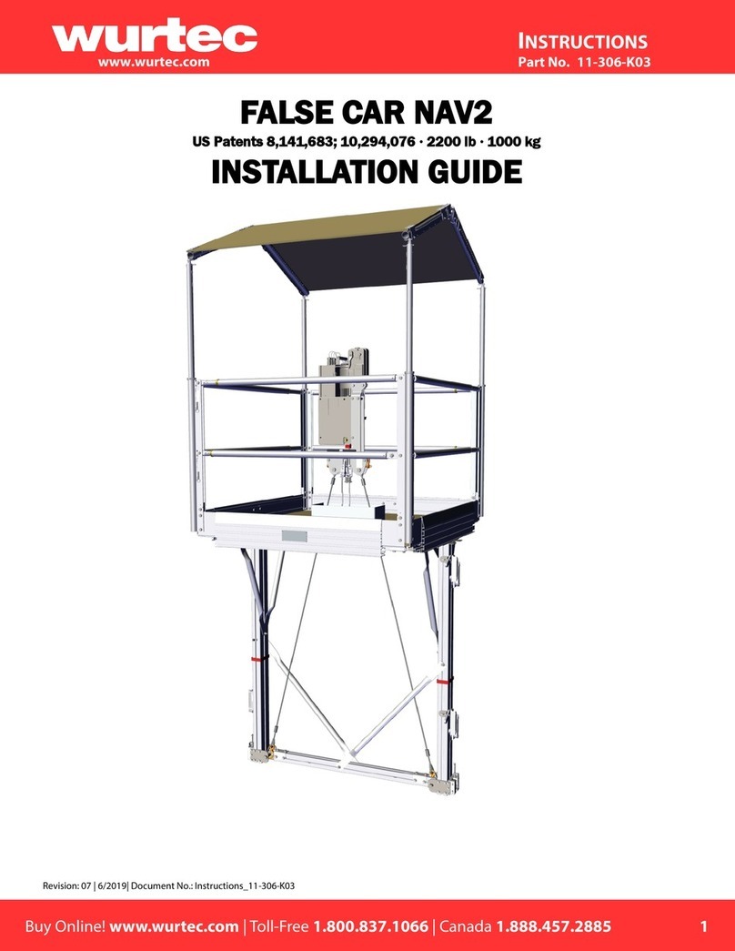
Wurtec OMEGA HOIST RIG User manual

16-296
70-180
6200 Brent Drive | Toledo, Ohio 43611
OMEGA HOIST RIG
Rev. 0 - 1/5/2017 | Release -
70-180

2
16-296
70-180
Table of Contents
Overview............................................................................................................................................................3
Hazards .............................................................................................................................................................3
Description.........................................................................................................................................................4
Features and Functions .....................................................................................................................................4
Installation......................................................................................................................................................6
Necessary Tools ............................................................................................................................................6
Set Up............................................................................................................................................................6
Opposite Side Configuration ..............................................................................................................................7
Recommended Inspection and Maintenance .....................................................................................................8
Hex-Bolts .......................................................................................................................................................8
Ankle Shackle ................................................................................................................................................8
Tap/Block Grippers ........................................................................................................................................9
Bill of Materials ...........................................................................................................................................10

3
16-296
70-180
CAUTION!
Overview
The purpose of this manual is to provide the user with detailed instrucons on the proper installaon and use of the
Omega Hoist Rig. This includes:
Hazards associated with the use of this product;
Recommended Personal Protecve Equipment (PPE);
Explanaons of the Features and Funcons of this product;
Installaon and Proper Use instrucons;
Recommended Maintenance and Inspecon Criteria.
Aer reading this manual, the reader will be able to properly install the Omega Hoist Rig on an omega rail and use it to
safely hoist materials in an elevator hoistway.
The equipment covered in this manual should only be installed, used, and serviced by qualied personnel trained in
proper work and safety procedures. This manual is intended to assist such trained individuals in the installaon and
use of this equipment and is not intended as a substute for proper training and experience.
This document or any other informaon regarding this equipment is not intended to cover all of the possible
situaons which may be encountered while using the equipment described herein. Should specic situaons arise
which are not covered by the informaon provided, or should the user desire further details, the specics should be
directed to Wurtec, Inc.
NOTE: In the eort of connuous product improvement, Wurtec, Inc. reserves the right to modify the design and
specicaons of this product at any me without noce.
WARNING!
Ensure that the Hex Head Bolts on the back of the Omega Hoist Rig are ghtened to 50 Lb-Ft (68 Nm). Failure to follow
proper rigging procedure may result in serious injury or death. Never stand under equipment being hoisted.

4
16-296
70-180
DESCRIPTION:
The Omega Hoist Rig is designed to provide a safe hoisng point by clamping onto an omega-shaped elevator guide rail.
Working Load Limit: 1000 Lbs (454 kg)
FEATURES AND FUNCTIONS:
The Omega Hoist Rig clamps onto the omega rail via four (4) Gripper Blocks engaged by two (2) 5/8-11 X 7” Hex Bolts.
There is an anchor shackle aached to the Hoisng Plate which provides a hoisng point.

5
16-296
70-180
The Tap Block which lies on the inside of the omega rail contains four (4) Round Grippers. These provide grip points on the
inside bends of the omega rail when the Gripper Blocks are drawn together by the hex bolts.

6
16-296
70-180
Installaon
Necessary Equipment
15/16” Socket
Torque Wrench
An-Seize Lubricant (such as Dow Corning Molykote 1000, Locte Moly-50, Spider Black)
Set Up
1. Loosen the Hex Bolts to spread the Gripper Blocks as
far apart as possible. Apply a thin, even coang of
an-seize lubricant to the bolt threads.
2. Place the Hoisng Plate against the back of the omega rail. Make sure the Gripper Blocks are spread out
far enough for the omega rail to t between them. The Tap Block should be located in the inside cavity
of the omega rail.

7
16-296
70-180
3. Push the Gripper Blocks toward each other and ghten the
Hex Bolts so that the Gripper Blocks squeeze the side anges
of the omega rail.
Tighten Hex Bolts to 50 Lb-Ft (68 Nm).
To switch to opposite conguraon:
1. Remove the screw pin from the shackle and out of the hole in the Hoist Plate.
2. If installed, remove the Omega Hoist Rig from the omega rail.
3. Replace the shackle and screw pin in the opposite hole in the Hoist Plate.
4. Flip the Omega Hoist Rig to the desired orientaon.
5. Install on the omega rail as directed in the Set Up instrucons.
4. You can now safely use the shackle on the corner of the Hoist
Plate as a hoist point.
WLL: 1000 Lbs (454 kg)
Opposite Side Conguraon
The Omega Hoist Rig can be used with the hoist point on either
the right or the le side of the omega rail.

8
16-296
70-180
Anchor Shackle
Before hoisng, ensure that the screw pin is completely and properly engaged in the shackle.
Recommended Inspecon and Maintenance
Hex Bolts
Inspect the Hex Bolts before each use. Check for damaged threads or cross-threading into the Tapped Gripper blocks. En-
sure that the threads of the Hex Bolts have sucient lubricaon on so that they are able to travel smoothly in either di-
recon of the thread path. Proper lubricaon will ensure sucient clamping force.
Recommended Thread Lubricant: Molykote 1000
Replacement Hex Bolt:
Part Number: 11540854
Descripon: 5/8-11 X 7” Grade 9 EcoGuard Finish Hex Head Cap Screw

9
16-296
70-180
Tap Block / Grippers
Ensure that there are four (4) Grippers in place in the Tap Block.

10
16-296
70-180
Bill of Materials
This manual suits for next models
1
Table of contents
Other Wurtec Lifting System manuals
Popular Lifting System manuals by other brands

Lehner Lifttechnik
Lehner Lifttechnik LIFTboy user manual

Dragon Wholesaling
Dragon Wholesaling LF750 user manual

Inter-fab
Inter-fab Portable i-Lift instruction manual

Ingersoll-Rand
Ingersoll-Rand 700C Parts, operation and maintenance manual

Jula
Jula Hamron 334-013 User instructions

Rockler
Rockler 69191 operating instructions