Wurth Elektronik OPHELIA-I User manual

OPHELIA-I REFERENCE MANUAL
2612011022000
VERSION 1.0
JANUARY 27, 2022

Abbreviations
Abbreviation Name Description
BER Bit Error Rate
DC Direct Current
ESD Electrostatic
Discharge
EV (Board) Evaluation (Board) Ophelia-I populated on motherboard with USB
interface for test and evaluation purpose.
FCC
Federal
Communications
Commission
GND Ground Ground signal level that corresponds to 0 V.
GPIO General Purpose
Input/Output
IC Integrated Circuit
I/O Input/output Pinout description
LDO Low Dropout Low dropout voltage regulator
Bluetooth LE Bluetooth Low
Energy
PCB Printed Circuit
Board
RAM Random Access
Memory
RF Radio frequency Describes wireless transmission.
RSSI Receive Signal
Strength Indicator
The RSSI indicates the strength of the RF signal. Its
value is always printed in two’s complement notation.
SMA SubMiniature
version A
SWD Serial Wire Debug
UART
Universal
Asynchronous
Receiver
Transmitter
Allows the serial communication with the module.
VDD Voltage Drain
Drain Supply voltage
VSWR Voltage Standing
Wave Ratio
Ophelia-I reference manual version 1.0 © January 2022
www.we-online.com/wireless-connectivity 2

Contents
1 Introduction 5
1.1 Operational description . . . . . . . . . . . . . . . . . . . . . . . . . . . . . 5
1.2 Blockdiagram................................... 6
1.3 Orderinginformation............................... 6
2 Electrical specifications 7
2.1 Recommended operating conditions . . . . . . . . . . . . . . . . . . . . . . 7
2.2 Absolute maximum ratings . . . . . . . . . . . . . . . . . . . . . . . . . . . . 7
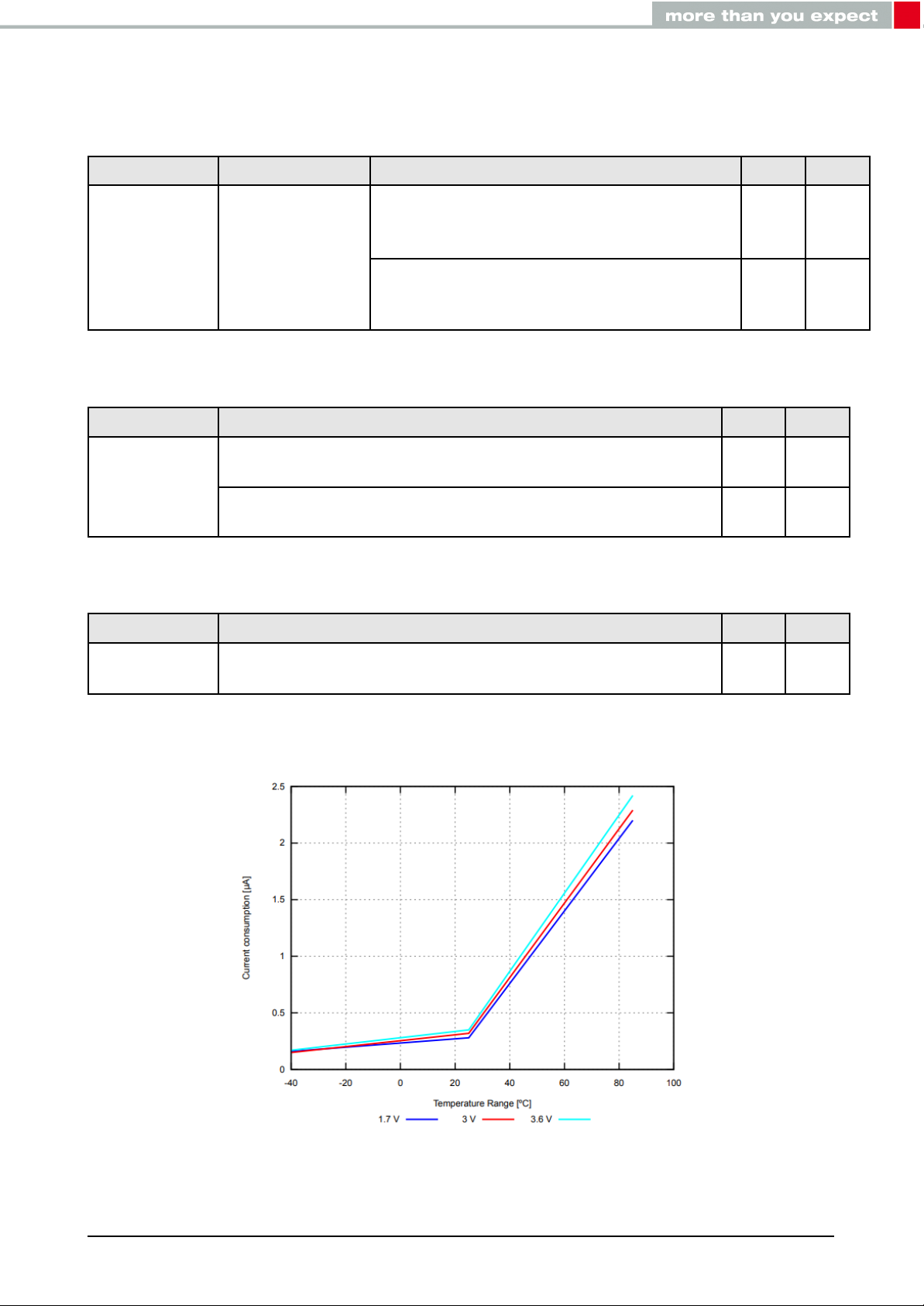
2.3 Powerconsumption................................ 8
2.3.1 Static................................... 8
2.4 Radiocharacteristics............................... 9
2.5 Pincharacteristics ................................ 10
3 Pinout 11
4 Antenna connection 13
4.1 On-boardPCBantenna ............................. 13
4.2 Externalantenna................................. 13
5 Custom firmware 14
5.1 Customerfirmware................................ 14
5.2 Contact for firmware requests . . . . . . . . . . . . . . . . . . . . . . . . . . 14
6 Firmware flashing using the production interface 15
7 Design in guide 16
7.1 Advice for schematic and layout . . . . . . . . . . . . . . . . . . . . . . . . . 16
7.2 Dimensioning of the micro strip antenna line . . . . . . . . . . . . . . . . . . 18
7.3 Antennaconnection ............................... 19
7.3.1 Simple short using internal antenna . . . . . . . . . . . . . . . . . . 20
7.3.2 22 pF coupling capacitor using internal antenna . . . . . . . . . . . 21
7.3.3 22 pF coupling capacitor using external antenna . . . . . . . . . . . 22
7.4 Antennafinetuning................................ 23
7.5 Antennasolutions ................................ 23
7.5.1 Wireantenna .............................. 23
7.5.2 Chipantenna .............................. 24
7.5.3 PCBantenna .............................. 24
7.5.4 Antennas provided by Würth Elektronik eiSos . . . . . . . . . . . . 25
7.5.4.1 2600130021 - Himalia - 2.4 GHz dipole antenna . . . . . . . . 25
8 Reference design 26
8.1 EV-Board ..................................... 27
8.1.1 Schematic................................ 27
8.1.2 Layout .................................. 28
9 Manufacturing information 29
9.1 Moisture sensitivity level . . . . . . . . . . . . . . . . . . . . . . . . . . . . . 29
9.2 Soldering ..................................... 29
9.2.1 Reflowsoldering ............................ 29
9.2.2 Cleaning................................. 30
Ophelia-I reference manual version 1.0 © January 2022
www.we-online.com/wireless-connectivity 3

9.2.3 Potting and coating . . . . . . . . . . . . . . . . . . . . . . . . . . . 30
9.2.4 Othernotations ............................. 31
9.3 ESDhandling................................... 31
9.4 Safety recommendations . . . . . . . . . . . . . . . . . . . . . . . . . . . . . 31
10 Physical specifications 33
10.1 Dimensions.................................... 33
10.2 Weight....................................... 33
10.3 Lightsensitivity .................................. 33
10.4 Moduledrawing.................................. 34
10.5 FootprintWE-FP-4+ ............................... 35
10.6 Antennafreearea ................................ 35
11 Marking 36
11.1 Lotnumber .................................... 36
12 Information for explosion protection 37
13 References 38
14 Important notes 39
14.1 General customer responsibility . . . . . . . . . . . . . . . . . . . . . . . . . 39
14.2 Customer responsibility related to specific, in particular safety-relevant ap-
plications ..................................... 39
14.3 Best care and attention . . . . . . . . . . . . . . . . . . . . . . . . . . . . . 39
14.4 Customer support for product specifications . . . . . . . . . . . . . . . . . . 39
14.5 Productimprovements.............................. 40
14.6 Productlifecycle ................................. 40
14.7 Propertyrights .................................. 40
14.8 General terms and conditions . . . . . . . . . . . . . . . . . . . . . . . . . . 40
15 Legal notice 41
15.1 Exclusionofliability................................ 41
15.2 Suitability in customer applications . . . . . . . . . . . . . . . . . . . . . . . 41
15.3 Trademarks .................................... 41
15.4 Usagerestriction ................................. 41
16 License terms 43
16.1 Limitedlicense .................................. 43
16.2 Usageandobligations .............................. 43
16.3 Ownership..................................... 44
16.4 Firmwareupdate(s)................................ 44
16.5 Disclaimer of warranty . . . . . . . . . . . . . . . . . . . . . . . . . . . . . . 44
16.6 Limitationofliability................................ 44
16.7 Applicable law and jurisdiction . . . . . . . . . . . . . . . . . . . . . . . . . . 45
16.8 Severabilityclause ................................ 45
16.9 Miscellaneous................................... 45
Ophelia-I reference manual version 1.0 © January 2022
www.we-online.com/wireless-connectivity 4

1 Introduction
1.1 Operational description
The Ophelia-I is a radio module for wireless communication between devices such as control
systems, remote controls, sensors etc. The module is based on the radio chipset nRF52805
from Nordic Semiconductor and is meant as hardware-only module: no firmware is imple-
mented on the module. It is customer’s responsibility to develop the firmware for the module
fulfilling the requirements of the specific application.
Since the Ophelia-I does not integrate any firmware, no radio certification is provided for
this radio module. Nevertheless, the Ophelia-I is ready for CE/RED, FCC, IC and TELEC.
The Ophelia-I hardware platform mounting Bluetooth®LE firmware has been tested within
the certification of Proteus-e [3]. Test reports can be requested from BDM or support.
Depending on the firmware developed and flashed on the module, a wide range of applica-
tions is possible. For example, the module can be configured to communicate with external
sensors, can use security configurations, and can be optimized for low power consumption.
Ultra small dimensions of 7 x 9 mm including a strongly miniaturized PCB antenna make
the Ophelia-I ideal for small form factor design. It is possible to connect an external antenna,
in case higher radio ranges are required.
For firmware development and all functional topics, please refer to the documentation and
resources available for the nRF52805 chipset [1].
For firmware customization topics, please refer to chapter
5
and to the Bluetooth®5.1 ra-
dio module Proteus-e [3].
Figure 1: Ophelia-I
Ophelia-I reference manual version 1.0 © January 2022
www.we-online.com/wireless-connectivity 5

1.2 Block diagram
Ophelia-I
Shielding
Wireless MCU
High accuracy
crystal
RF Filter & 50Ω
matching
UART,
Reset, GPIO,
SWD
Power
supply
DCDC voltage
regulator
ARM Cortex M4,
Flash, RAM
Radio core,
2.4GHz
50Ω port to λ/4
antenna
Antenna
external wiring
according to
reference design
Figure 2: Block diagram of the module
1.3 Ordering information
WE order code Description
2612011022000 Ophelia-I Module, Tape & Reel
2612019022001 Ophelia-I Evaluation Board
Table 1: Ordering information
Ophelia-I reference manual version 1.0 © January 2022
www.we-online.com/wireless-connectivity 6

2 Electrical specifications
Unless otherwise stated, the values specified are measured on the evaluation board of the
Ophelia-I with T=25°C, VDD=3 V, f=2.44 GHz, internal DC-DC converter in use.
Many electrical specifications depend on the specific firmware flashed on the
module. For example specifications with Bluetooth®LE 5.1 firmware, please
refer to the Proteus-e user manual [3]. For chipset specifications, please refer
to documentation from Nordic [1]
2.1 Recommended operating conditions
Description Min. Typ. Max. Unit
Ambient temperature -40 25 85 °C
Supply voltage (VDD) 1.8 3 3.6 V
Supply rise time (0V to ≥1.7V) 60 ms
Table 2: Recommended operating conditions
The on-chip power-on reset circuitry may not function properly for rise times
longer than the specified maximum.
An instable supply voltage may significantly decrease the radio performance
and stability.
2.2 Absolute maximum ratings
Parameter Min. Max. Unit
Supply voltage (VDD) -0.3 +3.9 V
Voltage on any digital pin (VDD<3.6V) -0.3 VDD+0.3 V
Voltage on any digital pin (VDD≥3.6V) -0.3 3.9 V
Input RF level 10 dBm
Flash endurance 10 000 Write/erase cycles
Table 3: Absolute maximum ratings
Ophelia-I reference manual version 1.0 © January 2022
www.we-online.com/wireless-connectivity 7

2.3 Power consumption
2.3.1 Static
Parameter Power Test conditions Value Unit
TX Current
consumption
Maximum out
put power
Transmitter only, 1Mbps Bluetooth®LE,
CPU current not included, from nRF52
data sheet
8 mA
Full module current consumption
(Proteus-e module, Bluetooth®LE
firmware)
9.3 mA
Table 4: Current consumption - transmitting
Parameter Test conditions Value Unit
RX Current
consumption
Receiver only, 1Mbps Bluetooth®LE, CPU current not
included, from nRF52 data sheet 6.1 mA
Full module current consumption (Proteus-e module,
Bluetooth®LE firmware) 6.8 mA
Table 5: Current consumption - receiving
Parameter Test conditions Value Unit
Current
consumption Sleep (system off mode) 0.3 µA
Table 6: Current consumption - low power
Figure 3: Sleep current (no RAM retention, wake on reset) over operating temperature range
Ophelia-I reference manual version 1.0 © January 2022
www.we-online.com/wireless-connectivity 8

2.4 Radio characteristics
Parameter Min. Max. Unit
Frequency 2360 2500 MHz
Table 7: Frequency range
Parameter Min. Max. Unit
RSSI accuracy valid range (±2dB) -90 -20 dBm
Table 8: RSSI accuracy
Parameter Value Unit
Enable TX or RX delay 140 µs
Enable TX or RX delay (fast mode) 40 µs
Disable TX delay 6 µs
Disable RX delay 0 µs
Table 9: Timing
Parameter Test conditions Value Unit
Output power Conducted +4 dBm
Radiated -4 dBm
Input sensitivity Conducted, BER=1E-3, 1Mbps, Bluetooth®LE -93 dBm
Conducted, BER=1E-3, 1Mbps, Bluetooth®LE, LDO mode -97 dBm
Radiated, BER=1E-3, 1Mbps, Bluetooth®LE -85 dBm
Table 10: Transmit and receive power
All transmit and receive power levels are measured on the evaluation board. The values
already include losses of transitions from module to motherboard to SMA or modules PCB
antenna. They are realistic values for the end application.
Ophelia-I reference manual version 1.0 © January 2022
www.we-online.com/wireless-connectivity 9

2.5 Pin characteristics
Specifications from nRF52 data sheet are reported here below.
Description Min. Typ. Max. Unit
Input high voltage 0.7 ×VDD VDD V
Input low voltage VSS 0.3 ×VDD V
Current at VSS+0.4 V, output set low, standard
drive, VDD ≥1.7V 1 2 4 mA
Current at VSS+0.4 V, output set low, high drive,
VDD ≥2.7 V 6 10 15 mA
Current at VSS+0.4 V, output set low, high drive,
VDD ≥1.7 V 3 mA
Current at VDD-0.4 V, output set high, standard
drive, VDD ≥1.7V 1 2 4 mA
Current at VDD-0.4 V, output set high, high
drive, VDD ≥2.7 V 6 9 14 mA
Current at VDD-0.4 V, output set high, high
drive, VDD ≥1.7 V 3 mA
Internal pull-up resistance 11 13 16 kΩ
Internal pull-down resistance 11 13 16 kΩ
Table 11: Pin characteristics
Ophelia-I reference manual version 1.0 © January 2022
www.we-online.com/wireless-connectivity 10

No Designation Type Description
1ANT I/O RF connection to PCB antenna. (see chapter
4
)
2RF I/O 50 ΩRF connection through radio front end to
transceiver part of chipset. (see chapter
4
)
3SWDIO I/O Serial wire input/output (SWD Interface).
4SWDCLK I/O Serial wire clock (SWD Interface).
5P0.21 /
nRESET I/O General purpose I/O. Configurable as pin reset.
6 P0.12 I/O General purpose I/O.
7VDD Supply Supply voltage
8 P0.05 / AIN3 I/O, analog
input General purpose I/O, ADC input.
9 P0.04 / AIN2 I/O, analog
input General purpose I/O, ADC input.
10 P0.14 I/O General purpose I/O
11 P0.00/XL1 I/O General purpose I/O, connection for 32.768 kHz
crystal
12 P0.01/XL2 I/O General purpose I/O, connection for 32.768 kHz
crystal
13 P0.16 I/O General purpose I/O
14 P0.18 I/O General purpose I/O
15 P0.20 I/O General purpose I/O
B1 GND Supply Ground
B2 GND Supply Ground
B3 GND Supply Ground
B4 GND Supply Ground
Table 12: Pinout, first part
Ophelia-I reference manual version 1.0 © January 2022
www.we-online.com/wireless-connectivity 12

4 Antenna connection
Ophelia-I’s smart antenna configuration allows the user to choose between two antenna
options: onboard PCB antenna and external antenna. Detailed description on how to imple-
ment different antenna solution is given in chapter
7.3
,
7.4
,
7.5
and
8
.
4.1 On-board PCB antenna
The Ophelia-I has an on-board PCB antenna optimized for strong miniaturization operating
in the 2.4 GHz frequency band. To use this integrated antenna, it has to be connected to the
radio chip by connecting the pins RF and ANT.
The use cases for the integrated antenna are miniaturization of the end appli-
cation and applications with required radio range of just few meters.
4.2 External antenna
For applications that use an external antenna, the Ophelia-I provides a 50 ΩRF signal on
pin RF of the module. In this configuration, pin ANT of the module has to be left open and
pin RF has to be connected to the external antenna via 50 Ωfeed line.
An external antenna is normally used to increase the achievable radio range,
at the cost of more space needed in the device/application. Also, an exter-
nal antenna could be needed to fit the specific application environment of the
module, for example when a metal housing is used.
Ophelia-I reference manual version 1.0 © January 2022
www.we-online.com/wireless-connectivity 13

5 Custom firmware
5.1 Customer firmware
A customer firmware is a firmware written and tested by the customer himself or a 3rd party
as a customer representative specifically for the hardware platform provided by a module.
This customer firmware (e.g. in form of an Intel hex file) will be implemented into the mod-
ule’s production process at our production side.
This also results in a customer exclusive module with a unique ordering number.
The additional information needed for this type of customer firmware, such as hardware spe-
cific details and details towards the development of such firmware are not available for the
public and can only be made available to qualified customers.
The qualification(s) of the standard module cannot be applied to this customer
firmware solution without a review and verification.
5.2 Contact for firmware requests
Please contact your local field sales engineer (FSE) or wireless-sales@we-online.com for
quotes regarding this topics.
Ophelia-I reference manual version 1.0 © January 2022
www.we-online.com/wireless-connectivity 14

6 Firmware flashing using the production interface
The Ophelia-I offers a serial wire debug and programming interface (SWD) for module flash
access. This interface can be used by customers to erase the entire chip and install their
own firmware.
Customers flashing their own firmware are fully responsible for certification,
declaration, listing and qualification.
Ophelia-I reference manual version 1.0 © January 2022
www.we-online.com/wireless-connectivity 15

7 Design in guide
7.1 Advice for schematic and layout
For users with less RF experience it is advisable to closely copy the relating evaluation
board with respect to schematic and layout, as it is a proven design. The layout should
be conducted with particular care, because even small deficiencies could affect the radio
performance and its range or even the conformity.
The following general advice should be taken into consideration:
• A clean, stable power supply is strongly recommended. Interference, especially oscil-
lation can severely restrain range and conformity.
• Variations in voltage level should be avoided.
• LDOs, properly designed in, usually deliver a proper regulated voltage.
• Blocking capacitors and a ferrite bead in the power supply line can be included to filter
and smoothen the supply voltage when necessary.
No fixed values for the filter parts can be recommended, as these depend on
the circumstances of the application (main power source, interferences etc.).
The use of an external reset IC should be considered particularly if one of the
following points is relevant:
• The slew rate of the power supply exceeds the electrical specifications.
• The effect of different current consumptions on the voltage level of bat-
teries or voltage regulators should be considered. The module draws
higher currents in certain scenarios like start-up or radio transmit which
may lead to a voltage drop on the supply. A restart under such circum-
stances should be prevented by ensuring that the supply voltage does
not drop below the minimum specifications.
• Voltage levels below the minimum recommended voltage level may lead
to malfunction. The /Reset pin of the module shall be held on LOW logic
level whenever the VCC is not stable or below the minimum operating
Voltage.
• Special care must be taken in case of battery powered systems.
• Elements for ESD protection should be placed on all pins that are accessible from the
outside and should be placed close to the accessible area. For example, when using
an external antenna the RF-pin could be accessible and should be protected in this
case.
Ophelia-I reference manual version 1.0 © January 2022
www.we-online.com/wireless-connectivity 16

• ESD protection for the antenna connection must be chosen such as to have a minimum
effect on the RF signal. For example, a protection diode with low capacitance such as
the 8231606A or a 68 nH air-core coil connecting the RF-line to ground give good
results.
• Placeholders for optional antenna matching or additional filtering are recommended.
• The antenna path should be kept as short as possible.
No fixed values for the filter and matching components can be recommended,
as they depend on the influencing circumstances of the application (antenna,
interferences etc.).
Figure 5: Layout example, layout of the corresponding evaluation board is published in the
evaluation board manual
• To avoid the risk of short circuits and interference there should be no routing under-
neath the module on the top layer of the baseboard.
• On the second layer, a ground plane is recommended, to provide good grounding and
shielding to any following layers and application environment.
• In case of integrated antennas it is required to have areas free from ground. This area
should be copied from the evaluation board.
• The area with the integrated antenna must overlap with the carrier board and should
not protrude, as it is matched to sitting directly on top of a PCB.
• Modules with integrated antennas should be placed with the antenna at the edge of
the main board. It should not be placed in the middle of the main board or far away
from the edge. This is to avoid tracks beside the antenna.
• Filter and blocking capacitors should be placed directly in the tracks without stubs, to
achieve the best effect.
• Antenna matching elements should be placed close to the antenna / connector, block-
ing capacitors close to the module.
Ophelia-I reference manual version 1.0 © January 2022
www.we-online.com/wireless-connectivity 17

• Ground connections for the module and the capacitors should be kept as short as
possible and with at least one separate through hole connection to the ground layer.
• ESD protection elements should be placed as close as possible to the exposed areas.
Figure 6: Placement of the module with integrated antenna
7.2 Dimensioning of the micro strip antenna line
Figure 7: Dimensioning the antenna feed line as micro strip
The antenna track has to be designed as a 50 Ωfeed line. The width W for a micro strip can
be calculated using the following equation:
W= 1.25 ×5.98 ×H
e50×√r+1.41
87
−Tmet!(1)
Ophelia-I reference manual version 1.0 © January 2022
www.we-online.com/wireless-connectivity 18

Example:
A FR4 material with εr= 4.3, a height H = 1000 µm and a copper thickness of Tmet = 18 µm
will lead to a trace width of W ~ 1.9 mm. To ease the calculation of the micro strip line (or
e.g. a coplanar) many calculators can be found in the internet.
• As rule of thumb a distance of about 3×W should be observed between the micro strip
and other traces / ground.
• The micro strip refers to ground, therefore there has to be the ground plane underneath
the trace.
• Keep the feeding line as short as possible.
7.3 Antenna connection
To provide best options following reference designs are tested:
• A simple short between the pins RF and ANT pin to be used if size and price is critical
and the range is uncritical.
• A 22 pF capacitor connecting RF and ANT pin to be used if size and price is less
critical, but an assembly variant with external antenna is also be used.
• A 22 pF capacitor connecting RF pin to an external antenna, for example Himalia [2],
described in chapter
7.5.4.1
. This configuration suits best if size and price is less
critical, but radio range should be optimized.
The reference designs use the same layer stack.
Figure 8: Stack-up
• Top layer is used for routing, filled with ground plane except the area under the module
and the antenna free area.
• Bottom layer is the ground plane with as few as possible routing dividing it.
Ophelia-I reference manual version 1.0 © January 2022
www.we-online.com/wireless-connectivity 19
Table of contents
Other Wurth Elektronik Wireless Module manuals
Popular Wireless Module manuals by other brands

Honeywell
Honeywell T7270B1009 Installation and operating instructions

NXP Semiconductors
NXP Semiconductors UM11490 user manual

Ebyte
Ebyte E104-BT10 user manual

Redline Communications
Redline Communications RDL-3000 Family product manual

DeDietrich
DeDietrich AD252 Assembly instructions

Toshiba
Toshiba GN-1040 Operator's manual