Wurth Elektronik PROTEUS-III User manual

PROTEUS-III REFERENCE MANUAL
2611011024000
VERSION 1.3
AUGUST 6, 2020

Revision history
Manual
version
FW
version
HW
version Notes Date
1.0 1.1.0 1.2 • Initial release February
2020
1.1 1.1.0 1.2
• Limitation of the
RF_DeviceName
to a
maximum of 31 bytes
• Added Annex
Additional CRC8
Information
and
Example codes for
host integration
June 2020
1.2 1.1.0 1.2 • corrected capacitor number. C28 changed
to C26 in section
Trace design
July 2020
1.3 1.1.0 1.2
• Updated section
Trace design
.
• Included figure
On-board PCB antenna
and
External antenna connection
.
August 2020
?For firmware history see chapter
Firmware history
Proteus-III reference manual version 1.3 © August 2020
www.we-online.com/wireless-connectivity 1

Abbreviations and abstract
Abbreviation Name Description
BTMAC Bluetooth®conform MAC address of the module used
on the RF-interface.
CS Checksum Byte wise XOR combination of the preceding fields.
DSSS Direct sequence
spread spectrum Technique to spread a message on the radio
DTM Direct test mode Mode to test Bluetooth®specific RF settings.
EV (Board) Evaluation (Board) Proteus-III populated on motherboard with USB
interface for test and evaluation purpose.
FEC Forward error
correction
Technique to correct received erroneous radio
messages
GAP Generic Access
Profile
The GAP provides a basic level of functionality that all
Bluetooth®devices must implement.
I/O Input/output Pinout description.
LESC Low energy
secure connection
Elliptic curve encryption method for Bluetooth®LE
encryption and authentication
LPM Low power mode Mode for efficient power consumption.
LRM Long range mode Radio mode with higher range and lower throughput.
MAC MAC address of the module.
MTU Maximum
transmission unit Maximum packet size of the Bluetooth®connection.
Payload The intended message in a frame / package.
RF Radio frequency Describes wireless transmission.
RSSI Receive Signal
Strength Indicator
The RSSI indicates the strength of the RF signal. Its
value is always printed in two’s complement notation.
Soft device Operating system used by the nRF52 chip.
User settings
Settings to configure the module. Any relation to a
specific entry in the user settings is marked in a
special font and can be found in chapter
8
.
UART
Universal
Asynchronous
Receiver
Transmitter
Allows the serial communication with the module.
[HEX] 0xhh Hexadecimal
All numbers beginning with 0x are hexadecimal
numbers. All other numbers are decimal, unless
stated otherwise.
Proteus-III reference manual version 1.3 © August 2020
www.we-online.com/wireless-connectivity 2

Contents
1. Introduction 10
1.1. Operational description . . . . . . . . . . . . . . . . . . . . . . . . . . . . . 10
1.1.1. Keyfeatures............................... 11
1.1.2. Connectivity............................... 12
1.2. Blockdiagram................................... 13
1.3. Orderinginformation............................... 13
2. Electrical specifications 14
2.1. Recommended operating conditions . . . . . . . . . . . . . . . . . . . . . . 14
2.2. Absolute maximum ratings . . . . . . . . . . . . . . . . . . . . . . . . . . . . 14
2.3. Powerconsumption................................ 15
2.3.1. Static................................... 15
2.3.2. Dynamic................................. 16
2.4. Radiocharacteristics............................... 18
2.5. Pincharacteristics ................................ 19
3. Pinout 20
4. Quick start 23
4.1. Minimal pin connections . . . . . . . . . . . . . . . . . . . . . . . . . . . . . 23
4.2. Antennaconnection ............................... 25
4.2.1. On-board PCB antenna . . . . . . . . . . . . . . . . . . . . . . . . . 25
4.2.2. Externalantenna ............................ 25
4.3. Powerup ..................................... 26
4.4. Quickstartexample................................ 27
5. Functional description 31
5.1. State indication using the LED pins . . . . . . . . . . . . . . . . . . . . . . . 33
5.2. Sleepmode.................................... 33
5.3. Identification of a Proteus-III device on the radio . . . . . . . . . . . . . . . . 34
5.4. Connection based data transmission, with or without security . . . . . . . . 34
5.4.1. Further information for a secure connection setup . . . . . . . . . . 35
5.4.1.1. Just works mode . . . . . . . . . . . . . . . . . . . . . . . . . . 35
5.4.1.2. StaticPasskey mode . . . . . . . . . . . . . . . . . . . . . . . . 38
5.4.1.3. LescPasskey mode . . . . . . . . . . . . . . . . . . . . . . . . . 41
5.4.1.4. LescNumComp mode . . . . . . . . . . . . . . . . . . . . . . . 45
5.4.1.5. Bonding............................... 50
5.5. Unidirectional connectionless data transmission using Beacons . . . . . . . 53
5.6. Energy-efficient distance estimation solutions . . . . . . . . . . . . . . . . . 54
5.7. Configure the module for low power consumption . . . . . . . . . . . . . . . 55
5.8. Start the direct test mode (DTM) . . . . . . . . . . . . . . . . . . . . . . . . 55
5.9. Using the 2 MBit and LE Coded phy . . . . . . . . . . . . . . . . . . . . . . 57
5.10. Connection setup using LE Coded phy . . . . . . . . . . . . . . . . . . . . . 58
6. Host connection 61
6.1. Serial interface: UART . . . . . . . . . . . . . . . . . . . . . . . . . . . . . . 61
6.1.1. Resetbehaviour............................. 61
Proteus-III reference manual version 1.3 © August 2020
www.we-online.com/wireless-connectivity 3

7. The command interface 62
7.1. Scan for other modules in range . . . . . . . . . . . . . . . . . . . . . . . . 64
7.1.1. CMD_SCANSTART_REQ . . . . . . . . . . . . . . . . . . . . . . . 64
7.1.2. CMD_SCANSTOP_REQ . . . . . . . . . . . . . . . . . . . . . . . . 64
7.1.3. CMD_GETDEVICES_REQ . . . . . . . . . . . . . . . . . . . . . . . 65
7.1.3.1. Example1.............................. 66
7.1.4. CMD_RSSI_IND ............................ 66
7.1.5. CMD_BEACON_RSP . . . . . . . . . . . . . . . . . . . . . . . . . . 67
7.2. Setupconnections ................................ 68
7.2.1. CMD_CONNECT_REQ . . . . . . . . . . . . . . . . . . . . . . . . 68
7.2.2. CMD_CONNECT_IND . . . . . . . . . . . . . . . . . . . . . . . . . 68
7.2.3. CMD_SECURITY_IND . . . . . . . . . . . . . . . . . . . . . . . . . 68
7.2.4. CMD_CHANNELOPEN_RSP . . . . . . . . . . . . . . . . . . . . . 69
7.2.5. CMD_DISCONNECT_REQ . . . . . . . . . . . . . . . . . . . . . . 69
7.2.6. CMD_DISCONNECT_IND . . . . . . . . . . . . . . . . . . . . . . . 70
7.2.7. CMD_PHYUPDATE_REQ . . . . . . . . . . . . . . . . . . . . . . . 70
7.2.8. CMD_PHYUPDATE_IND . . . . . . . . . . . . . . . . . . . . . . . . 71
7.2.9. CMD_PASSKEY_REQ . . . . . . . . . . . . . . . . . . . . . . . . . 71
7.2.10. CMD_PASSKEY_IND . . . . . . . . . . . . . . . . . . . . . . . . . . 72
7.2.11. CMD_DISPLAY_PASSKEY_IND . . . . . . . . . . . . . . . . . . . . 72
7.2.12. CMD_NUMERIC_COMP_REQ . . . . . . . . . . . . . . . . . . . . 72
7.2.13. CMD_GETBONDS_REQ . . . . . . . . . . . . . . . . . . . . . . . . 73
7.2.13.1. Example1.............................. 73
7.2.14. CMD_DELETEBONDS_REQ . . . . . . . . . . . . . . . . . . . . . 74
7.2.14.1. Example1.............................. 74
7.2.14.2. Example2.............................. 75
7.3. Transmit and receive data . . . . . . . . . . . . . . . . . . . . . . . . . . . . 76
7.3.1. CMD_DATA_REQ............................ 76
7.3.2. CMD_TXCOMPLETE_RSP . . . . . . . . . . . . . . . . . . . . . . 76
7.3.3. CMD_DATA_IND ............................ 77
7.3.4. CMD_SETBEACON_REQ . . . . . . . . . . . . . . . . . . . . . . . 77
7.3.5. CMD_BEACON_IND . . . . . . . . . . . . . . . . . . . . . . . . . . 77
7.4. Configuring the module and modifying the device settings . . . . . . . . . . 79
7.4.1. CMD_SET_REQ ............................ 79
7.4.1.1. Example1.............................. 80
7.4.1.2. Example2.............................. 80
7.4.2. CMD_GET_REQ ............................ 81
7.4.2.1. Example1.............................. 81
7.5. Manage the device state . . . . . . . . . . . . . . . . . . . . . . . . . . . . . 82
7.5.1. CMD_GETSTATE_REQ . . . . . . . . . . . . . . . . . . . . . . . . 82
7.5.1.1. Example1.............................. 82
7.5.2. CMD_RESET_REQ........................... 83
7.5.3. CMD_SLEEP_REQ........................... 83
7.5.4. CMD_SLEEP_IND ........................... 84
7.5.5. CMD_FACTORYRESET_REQ . . . . . . . . . . . . . . . . . . . . . 84
7.5.6. CMD_UARTDISABLE_REQ . . . . . . . . . . . . . . . . . . . . . . 85
7.5.7. CMD_UARTENABLE_IND . . . . . . . . . . . . . . . . . . . . . . . 86
7.5.8. CMD_BOOTLOADER_REQ . . . . . . . . . . . . . . . . . . . . . . 86
Proteus-III reference manual version 1.3 © August 2020
www.we-online.com/wireless-connectivity 4

7.6. Run the Bluetooth test modes . . . . . . . . . . . . . . . . . . . . . . . . . . 88
7.6.1. CMD_DTMSTART_REQ . . . . . . . . . . . . . . . . . . . . . . . . 88
7.6.2. CMD_DTM_REQ ............................ 88
7.6.2.1. Example: Transmission, 16 times 0x0F, channel 0 . . . . . . . 90
7.6.2.2. Example: Receiver, channel 0 . . . . . . . . . . . . . . . . . . . 91
7.6.2.3. Example: Transmission, carrier test, channel 0 . . . . . . . . . 92
7.6.2.4. Example: Set TX power to -4 dBm . . . . . . . . . . . . . . . . 92
7.6.2.5. Example: Set PHY to 2MBit mode . . . . . . . . . . . . . . . . 92
7.7. Switching GPIOs by remote control . . . . . . . . . . . . . . . . . . . . . . . 94
7.7.1. CMD_GPIO_LOCAL_WRITECONFIG_REQ . . . . . . . . . . . . . 94
7.7.1.1. Example: Configure two GPIOs to output high . . . . . . . . . . 95
7.7.2. CMD_GPIO_LOCAL_READCONFIG_REQ . . . . . . . . . . . . . 96
7.7.2.1. Example: Read the current GPIO configuration . . . . . . . . . 97
7.7.3. CMD_GPIO_REMOTE_WRITECONFIG_REQ . . . . . . . . . . . . 98
7.7.3.1. Example: Configure two GPIOs of the connected remote device
tooutputhigh............................ 99
7.7.4. CMD_GPIO_REMOTE_READCONFIG_REQ . . . . . . . . . . . . 100
7.7.4.1. Example: Read the current GPIO configuration of the connect-
edremotedevice.......................... 101
7.7.5. CMD_GPIO_REMOTE_WRITE_REQ . . . . . . . . . . . . . . . . . 102
7.7.5.1. Example: Set a remote output GPIO to low . . . . . . . . . . . 103
7.7.6. CMD_GPIO_REMOTE_READ_REQ . . . . . . . . . . . . . . . . . 104
7.7.6.1. Example: Read the values of remote GPIOs . . . . . . . . . . . 105
7.7.7. CMD_GPIO_LOCAL_WRITE_REQ . . . . . . . . . . . . . . . . . . 106
7.7.7.1. Example: Set a local output GPIO to low . . . . . . . . . . . . . 107
7.7.8. CMD_GPIO_LOCAL_READ_REQ . . . . . . . . . . . . . . . . . . 108
7.7.8.1. Example: Read the values of local GPIOs . . . . . . . . . . . . 109
7.7.9. CMD_GPIO_REMOTE_WRITECONFIG_IND . . . . . . . . . . . . 110
7.7.9.1. Example: Two GPIOs have been configured by the connected
remote device to output high . . . . . . . . . . . . . . . . . . . 110
7.7.10. CMD_GPIO_REMOTE_WRITE_IND . . . . . . . . . . . . . . . . . 111
7.7.10.1. Example: GPIOs have been written via remote access . . . . . 111
7.7.11. CMD_GPIO_LOCAL_WRITE_IND . . . . . . . . . . . . . . . . . . 112
7.7.11.1. Example: GPIOs of the remote device have been written by its
localhost .............................. 112
7.8. Othermessages ................................. 113
7.8.1. CMD_ERROR_IND........................... 113
7.9. Messageoverview ................................ 114
8. UserSettings - Module configuration values 118
8.1. FS_DeviceInfo: Read the chip type and OS version . . . . . . . . . . . . . . 118
8.1.1. Example1................................ 119
8.2. FS_FWVersion: Read the firmware version . . . . . . . . . . . . . . . . . . 120
8.2.1. Example1................................ 120
8.3. FS_MAC: Read the MAC address . . . . . . . . . . . . . . . . . . . . . . . . 121
8.3.1. Example1................................ 121
8.4. FS_BTMAC: Read the Bluetooth conform MAC address . . . . . . . . . . . 122
8.4.1. Example1................................ 122
Proteus-III reference manual version 1.3 © August 2020
www.we-online.com/wireless-connectivity 5
8.5. FS_SerialNumber: Read the serial number of the module . . . . . . . . . . 123
8.5.1. Example1................................ 123
8.6. RF_DeviceName: Modify the device name . . . . . . . . . . . . . . . . . . . 124
8.6.1. Example1................................ 124
8.6.2. Example2................................ 124
8.7. RF_StaticPasskey: Modify the static passkey . . . . . . . . . . . . . . . . . 126
8.7.1. Example1................................ 126
8.7.2. Example2................................ 126
8.8. RF_SecFlags: Modify the security settings . . . . . . . . . . . . . . . . . . . 127
8.8.1. Example1................................ 128
8.8.2. Example2................................ 129
8.9. RF_SecFlagsPerOnly: Modify the security settings (Peripheral only mode) . 130
8.9.1. Example1................................ 130
8.9.2. Example2................................ 130
8.10. RF_ScanFlags: Modify the scan behavior . . . . . . . . . . . . . . . . . . . 131
8.10.1.Example1................................ 131
8.10.2.Example2................................ 131
8.11. RF_BeaconFlags: Interprete the advertising data . . . . . . . . . . . . . . . 133
8.11.1.Example1................................ 133
8.11.2.Example2................................ 134
8.12. RF_AdvertisingTimeout: Modify the advertising timeout . . . . . . . . . . . 135
8.12.1.Example1................................ 135
8.12.2.Example2................................ 135
8.13. RF_AdvertisingFlags: Configure the advertising packet . . . . . . . . . . . . 136
8.13.1.Example1................................ 136
8.13.2.Example2................................ 136
8.14. RF_ScanFactor: Modify the scan factor . . . . . . . . . . . . . . . . . . . . 138
8.14.1.Example1................................ 138
8.14.2.Example2................................ 138
8.15. RF_ScanTiming: Modify the scan timing . . . . . . . . . . . . . . . . . . . . 139
8.15.1.Example1................................ 140
8.15.2.Example2................................ 140
8.16. RF_ConnectionTiming: Modify the connection timing . . . . . . . . . . . . . 141
8.16.1.Example1................................ 142
8.16.2.Example2................................ 142
8.17. RF_TXPower: Modify the output power . . . . . . . . . . . . . . . . . . . . . 143
8.17.1.Example1................................ 143
8.17.2.Example2................................ 143
8.18. RF_SPPBaseUUID: Configure the SPP base UUID . . . . . . . . . . . . . . 145
8.18.1.Example1................................ 145
8.18.2.Example2................................ 145
8.19. RF_Appearance: Configure the appearance of the device . . . . . . . . . . 147
8.19.1.Example1................................ 147
8.19.2.Example2................................ 147
8.20. UART_ConfigIndex: Modify the UART speed . . . . . . . . . . . . . . . . . 148
8.20.1.Example1................................ 150
8.20.2.Example2................................ 150
8.21. CFG_Flags: Configure the module . . . . . . . . . . . . . . . . . . . . . . . 151
8.21.1.Example1................................ 151
Proteus-III reference manual version 1.3 © August 2020
www.we-online.com/wireless-connectivity 6

8.21.2.Example2................................ 151
8.22. DIS_ManufacturerName: Configure the manufacturer name . . . . . . . . . 153
8.22.1.Example1................................ 153
8.22.2.Example2................................ 153
8.23. DIS_ModelNumber: Configure the model number . . . . . . . . . . . . . . . 155
8.23.1.Example1................................ 155
8.23.2.Example2................................ 155
8.24. DIS_SerialNumber: Configure the serial number . . . . . . . . . . . . . . . 156
8.24.1.Example1................................ 156
8.24.2.Example2................................ 156
8.25. DIS_HWVersion: Configure the HW version . . . . . . . . . . . . . . . . . . 157
8.25.1.Example1................................ 157
8.25.2.Example2................................ 157
8.26. DIS_SWVersion: Configure the SW version . . . . . . . . . . . . . . . . . . 158
8.26.1.Example1................................ 158
8.26.2.Example2................................ 158
8.27. DIS_Flags: Configure the device information service . . . . . . . . . . . . . 159
8.27.1.Example1................................ 159
8.27.2.Example2................................ 159
9. Timing parameters 163
9.1. Resetandsleep ................................. 163
9.2. Bluetooth LE timing parameters . . . . . . . . . . . . . . . . . . . . . . . . . 163
9.3. Connection establishment . . . . . . . . . . . . . . . . . . . . . . . . . . . . 163
9.4. Connection based data transmission . . . . . . . . . . . . . . . . . . . . . . 164
9.4.1. Maximum data throughput . . . . . . . . . . . . . . . . . . . . . . . 165
10.Peripheral only mode 166
10.1. Reasons to use the peripheral only mode . . . . . . . . . . . . . . . . . . . 166
10.2. Restrictions.................................... 166
10.3. How to use the peripheral only mode . . . . . . . . . . . . . . . . . . . . . . 167
10.4. Moreinformation ................................. 167
10.4.1.Radio................................... 167
10.4.2.UART................................... 167
11.Remote GPIO control 170
11.1. Supported GPIO_IDs for remote and local control . . . . . . . . . . . . . . . 175
12.Customizing the Proteus-III 176
12.1. DIS - Device information service . . . . . . . . . . . . . . . . . . . . . . . . 176
12.2. UUID........................................ 176
12.3. Appearance.................................... 176
13.Custom firmware 177
13.1. Custom configuration of standard firmware . . . . . . . . . . . . . . . . . . 177
13.2. Customer specific firmware . . . . . . . . . . . . . . . . . . . . . . . . . . . 177
13.3. Customerfirmware................................ 177
13.4. Contact for firmware requests . . . . . . . . . . . . . . . . . . . . . . . . . . 178
Proteus-III reference manual version 1.3 © August 2020
www.we-online.com/wireless-connectivity 7

14.Firmware updates 179
14.1. Firmware flashing using the production interface . . . . . . . . . . . . . . . 179
14.2. Firmware update using the Proteus-III OTA bootloader . . . . . . . . . . . . 179
14.2.1. Firmware update steps using the Nordic nRF Toolbox app . . . . . 181
15.Firmware history 183
16.Design in guide 184
16.1. Advice for schematic and layout . . . . . . . . . . . . . . . . . . . . . . . . . 184
16.2. Dimensioning of the micro strip antenna line . . . . . . . . . . . . . . . . . . 186
16.3. Antennasolutions ................................ 187
16.3.1.Wireantenna .............................. 188
16.3.2.Chipantenna .............................. 188
16.3.3.PCBantenna .............................. 188
16.3.4. Antennas provided by Würth Elektronik eiSos . . . . . . . . . . . . 189
16.3.4.1. 2600130021 - Himalia - 2.4 GHz dipole antenna . . . . . . . . 189
17.Reference design 190
17.1. EV-Board ..................................... 191
17.2. Tracedesign ................................... 194
18.Manufacturing information 197
18.1. Moisture sensitivity level . . . . . . . . . . . . . . . . . . . . . . . . . . . . . 197
18.2. Soldering ..................................... 197
18.2.1. Reflow soldering . . . . . . . . . . . . . . . . . . . . . . . . . . . . 197
18.2.2.Cleaning................................. 199
18.2.3.Othernotations ............................. 199
18.3. ESDhandling................................... 199
18.4. Safety recommendations . . . . . . . . . . . . . . . . . . . . . . . . . . . . . 200
19.Physical dimensions 201
19.1. Dimensions.................................... 201
19.2. Weight....................................... 201
19.3. Moduledrawing.................................. 202
19.4. Footprint...................................... 203
19.5. Antennafreearea ................................ 203
20.Marking 204
20.1. Lotnumber .................................... 204
20.2. General labeling information . . . . . . . . . . . . . . . . . . . . . . . . . . . 205
21.Information for Ex protection 206
22.Bluetooth SIG listing/qualification 207
22.1. Qualification steps when referencing the Proteus-III . . . . . . . . . . . . . . 207
23.Regulatory compliance information 209
23.1. ImportantnoticeEU ............................... 209
23.2. Important notice FCC . . . . . . . . . . . . . . . . . . . . . . . . . . . . . . 209
23.3. Conformity assessment of the final product . . . . . . . . . . . . . . . . . . 209
Proteus-III reference manual version 1.3 © August 2020
www.we-online.com/wireless-connectivity 8

23.4. Exemptionclause................................. 209
23.5. EU Declaration of conformity . . . . . . . . . . . . . . . . . . . . . . . . . . 210
23.6. FCC Compliance Statement . . . . . . . . . . . . . . . . . . . . . . . . . . . 211
23.7. IC Compliance Statement . . . . . . . . . . . . . . . . . . . . . . . . . . . . 211
23.8. FCC and IC requirements to OEM integrators . . . . . . . . . . . . . . . . . 211
23.8.1. Pre-certified antennas . . . . . . . . . . . . . . . . . . . . . . . . . 213
23.9. ARIB Declaration of conformity . . . . . . . . . . . . . . . . . . . . . . . . . 214
23.9.1.Label................................... 214
23.9.2. Certified antennas . . . . . . . . . . . . . . . . . . . . . . . . . . . 214
24.Important notes 215
24.1. General customer responsibility . . . . . . . . . . . . . . . . . . . . . . . . . 215
24.2. Customer responsibility related to specific, in particular safety-relevant ap-
plications ..................................... 215
24.3. Best care and attention . . . . . . . . . . . . . . . . . . . . . . . . . . . . . 215
24.4. Customer support for product specifications . . . . . . . . . . . . . . . . . . 215
24.5. Product improvements . . . . . . . . . . . . . . . . . . . . . . . . . . . . . . 216
24.6. Productlifecycle ................................. 216
24.7. Propertyrights .................................. 216
24.8. General terms and conditions . . . . . . . . . . . . . . . . . . . . . . . . . . 216
25.Legal notice 217
25.1. Exclusion of liability . . . . . . . . . . . . . . . . . . . . . . . . . . . . . . . . 217
25.2. Suitability in customer applications . . . . . . . . . . . . . . . . . . . . . . . 217
25.3. Trademarks .................................... 217
25.4. Usagerestriction ................................. 217
26.License terms 219
26.1. Limitedlicense .................................. 219
26.2. Usage and obligations . . . . . . . . . . . . . . . . . . . . . . . . . . . . . . 219
26.3. Ownership..................................... 220
26.4. Firmwareupdate(s)................................ 220
26.5. Disclaimer of warranty . . . . . . . . . . . . . . . . . . . . . . . . . . . . . . 220
26.6. Limitation of liability . . . . . . . . . . . . . . . . . . . . . . . . . . . . . . . . 221
26.7. Applicable law and jurisdiction . . . . . . . . . . . . . . . . . . . . . . . . . . 221
26.8. Severabilityclause ................................ 221
26.9. Miscellaneous................................... 221
A. Additional CRC8 Information 224
A.1. Example CRC8 Implementation . . . . . . . . . . . . . . . . . . . . . . . . . 224
A.1.1. CRC8 Test Vectors . . . . . . . . . . . . . . . . . . . . . . . . . . . 224
B. Example codes for host integration 225
Proteus-III reference manual version 1.3 © August 2020
www.we-online.com/wireless-connectivity 9

1. Introduction
1.1. Operational description
The Proteus-III module is a radio sub module/device for wireless communication between
devices such as control systems, remote controls, sensors et cetera. On the basis of
Bluetooth®LE 5.1 it offers a fast and secure data transmission of data packages between
two or more parties (point to point topology). A serial interface (UART) is available for com-
munication with the host system.
The Proteus-III uses the Bluetooth®LE standard to provide general data transmission be-
tween several devices. The standard itself offers a wide range of configurations and pos-
sibilities to suit and optimize sophisticated customer applications. To fulfill the needs and
specifications of such applications a tailored firmware can be developed on the basis of the
Proteus-III hardware. This includes the connection and communication to custom sensors,
custom Bluetooth®LE profiles, timing configurations, security configuration as well as power
consumption optimizations.
Even with it’s small dimensions of 8 x 12 mm the Proteus-III provides a strongly miniaturized
integrated PCB antenna. Beside it is possible to connect an external antenna if high radio
ranges are of interest.
The main functionality is accessible through pads with edge castellation. This offers easy
prototype building as it is suitable for hand soldering. More optional GPIOs without enlarg-
ing the size are accessible through land grid pads that can only be connected through reflow
process.
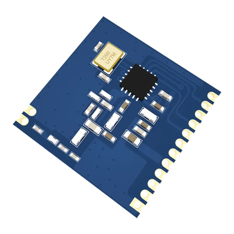
Figure 1: Proteus-III
Proteus-III reference manual version 1.3 © August 2020
www.we-online.com/wireless-connectivity 10

1.1.1. Key features
The Proteus-III offers the following key features that are described in the manual in more
detail:
SPP-like connection-based secured data transmission: The Proteus-III firmware imple-
ments an SPP-like Bluetooth®LE profile that allows the bidirectional data transmission
between several Proteus-III and/or to other Bluetooth®LE devices implementing the
AMBER SPP profile. Any module in the network can initiate a connection setup. Se-
cured connections allow the transmission of encrypted data.
Remote GPIOs: The Proteus-III firmware allows to switch free module GPIOs via remote
control. More information can be found in chapter
11
.
Advanced customization capabilities: The configurable Device Information Service (DIS),
the UUID and the appearance of the Bluetooth®LE profile, enable to personalize the
Proteus-III to fuse with the user’s end product.
Low power position sensing solutions: The current TX power of any Proteus-III is always
transmitted with each advertising packet when the module is in command mode. With
this, distance estimation and position sensing solutions can be realized conveniently
by performing a passive scan.
Fast serial interface: The Proteus-III offers a UART-interface to communicate with a host
using a user-defined baud rate and a simple command interface.
Latest microprocessor generation provided by Nordic Semiconductor nRF52 series:
The heart of the Proteus-III is a Bluetooth®LE chip of the nRF52 series offering high
performance values combined with low power consumption. It is a 32 Bit ARM Cortex-
M4F CPU with 1024kB flash + 256kB RAM and up to 8dBm output power.
Bluetooth®5 stack: The Bluetooth®5 stack enables fast and energy efficient data trans-
mission using state-of-the-art technology of Nordic Semiconductors.
High throughput mode: The Proteus-III contains the so called "High throughput mode"
that allows to send up to 4 data packets per connection interval. This increases signif-
icantly the throughput. This mode and its usage is described in Application Note AN-
R006.
All Bluetooth®LE roles supported: The integrated Bluetooth®LE stack supports all Bluetooth®LE
roles. Depending on the current state of operation the Proteus-III firmware automati-
cally switches its role to execute the user’s instructions.
Flexible wired interfacing: The Proteus-III is equipped with extra pins suited for custom
device/sensor connection. With help of these, a tailored firmware can be developed
which is optimized to the customer’s needs. The pins can be configured to various
functions such as UART, SPI, I2C, ADC, PWM, NFC and GPIO.
OTA firmware update: The Proteus-III firmware provides over the air firmware update ca-
pabilities. Firmware updates can be applied using the Nordic Apps for cell phones.
Proteus-III reference manual version 1.3 © August 2020
www.we-online.com/wireless-connectivity 11

Peripheral only mode: The Proteus-III firmware provides the "peripheral only" operation
mode (see chapter
10
), that allows the easy adaption of already existing custom hard-
ware with the Bluetooth®LE interface. By default, this mode offers the static passkey
pairing method with bonding and a transparent UART interface. With this, custom hard-
ware can be accessed by mobile Bluetooth®LE devices (like smart phones including
a custom App) using an authenticated and encrypted Bluetooth®LE link without the
need of configuring the module.
Additional Bluetooth®5 radio modes: The Proteus-III provides the advanced radio modes
2 MBit mode for faster data transmission and the LE coded mode, that allows long
range data transmissions. For more information, see chapter
5.9
.
Long range connect: For backward compatibility reasons, a Bluetooth®LE connection is
setup using the legacy 1MBit radio mode and can then be updated to long range mode.
The Proteus-III allows in addition to setup the connection immediately using the long
range mode, such that even connections can be initiated on high distances. More
information can be found in chapter
5.10
.
Fast sensor data transmission via Beacons: The Proteus-III supports the transmission
and reception of Beacons. Beacons are fast broadcast messages that allow the energy-
efficient unidirectional transmission of data. Especially in sensor networks, this feature
is suitable for the frequent transmission of measurement data as it avoids the need for
a connection-based communication and therefore is more energy efficient.
1.1.2. Connectivity
The Bluetooth®LE standard allows to setup a network with various Bluetooth®LE devices
from different manufacturers. To be able to communicate with Proteus-III devices, the AM-
BER SPP-like profile must be known and implemented by all network participants.
The advanced developer guide of Proteus-III (Application note ANR009) contains the design
data of the AMBER SPP-like profile, to implement it for example in smart phone apps.
Proteus-III reference manual version 1.3 © August 2020
www.we-online.com/wireless-connectivity 12

1.2. Block diagram
Proteus-III
Shielding
Wireless MCU
High accuracy
crystal
RF Filter & 50Ω
matching
UART,
Reset, GPIO,
SWD
Power
supply
DCDC voltage
regulator
ARM Cortex M4,
Flash, RAM
Radio core,
2.4GHz
Bluetooth 5.1
50Ω port to λ/4
antenna
external
wiring
Antenna
Figure 2: Block diagram of the module
1.3. Ordering information
WE order code Description
2611011024000 Proteus-III Bluetooth®LE Module, Tape & Reel
2611011024009 Development Kit including 3×Proteus-III
2611019024001 Bluetooth®LE Evaluation Kit with Proteus-III EV
board
2611036024001 USB Dongle Proteus-III Plug, integrated antenna
Table 1: Ordering information
Proteus-III reference manual version 1.3 © August 2020
www.we-online.com/wireless-connectivity 13

2. Electrical specifications
As not otherwise stated measured on the evaluation board Proteus-III-EV with T=25°C,
VDDS=3V, f=2.44GHz, internal DC-DC converter in use.
2.1. Recommended operating conditions
Description Min. Typ. Max. Unit
Ambient temperature -40 25 85 °C
Supply voltage (VDDS) 1.813 3.6 V
Supply rise time (0V to ≥1.7V) 60 ms
Table 2: Recommended operating conditions
The on-chip power-on reset circuitry may not function properly for rise times
longer than the specified maximum.
An instable supply voltage may significantly decrease the radio performance
and stability.
2.2. Absolute maximum ratings
Description Min. Typ. Max. Unit
Supply voltage (VDD) -0.3 +3.9 V
Voltage on any digital pin, VDD≤3.6V -0.3 VDD+0.3 V
Voltage on any digital pin, VDD≥3.6V -0.3 3.9 V
Input RF level 10 dBm
Flash endurance 10 000 Write/erase cycles
Table 3: Absolute maximum ratings
1Power fail comparator is set to 1.8V to avoid flash fail due to voltage drop.
Proteus-III reference manual version 1.3 © August 2020
www.we-online.com/wireless-connectivity 14

2.3. Power consumption
2.3.1. Static
Continuous test mode Min. Typ. Max. Unit
TX current consumption at +8 dBm 16.41mA
TX current consumption at 0 dBm 6.41mA
RX current consumption 6.251mA
TX current consumption at +8 dBm 18.92mA
TX current consumption at 0 dBm 82mA
RX current consumption 7.72mA
Sleep (system off mode) 0.4 µA
Reduction through
CMD_UARTDISABLE_REQ
550 µA
Table 4: Power consumption for 100% transmission/reception
Due to the Bluetooth®LE time slot operation, the real operating currents are
reduced significantly and depend on the user selectable advertising and con-
nection interval settings.
1Transmitter only with DC/DC converter from nRF52 data sheet, CPU current not included.
2Full module power consumption.
Proteus-III reference manual version 1.3 © August 2020
www.we-online.com/wireless-connectivity 15

Figure 3: Radio transmitting @ 8 dBm output power, 1 Mbps Bluetooth®LE mode, Clock =
HFXO, Regulator = DC/DC (typical values)
2.3.2. Dynamic
Besides the static TX, RX, idle and sleep current the average current is of interest. Here
an example for a typical behavior of a peripheral device in advertising mode (see Figure
4
).
Currents and state durations are dependent on the configuration of the module. In this state
the module transmits the advertising packets on the three advertising channels.
Nordic Semiconductor provides an online tool calculating the average current of a Bluetooth®
connection. It can be accessed at https://devzone.nordicsemi.com/power/ .
Proteus-III reference manual version 1.3 © August 2020
www.we-online.com/wireless-connectivity 16

2.4. Radio characteristics
Specifications of Timing and RSSI value
Description Min. Typ. Max. Unit
RSSI accuracy valid range (±2dB) -90 -20 dBm
Enable TX or RX delay 140 µs
Enable TX or RX delay (fast mode) 40 µs
Disable TX delay 6 µs
Disable RX delay 0 µs
Table 5: Timing and RSSI
Description Typ. Unit
Output power conducted +6 dBm
Output power integrated antenna +4 dBm
Input sensitivity conducted (BER=1E-3, 1Mbps) -92 dBm
Input sensitivity integrated antenna (BER=1E-3, 1Mbps) -90 dBm
Table 6: Transmit and Receive Power
All transmit and receive power levels are measured on the evaluation board. The values
already include losses of transitions from module to motherboard to SMA or modules PCB
antenna. They are realistic values for the end application. Sensitivity in the table above is
stated for the common used bit error rate of 0.1%. In the table below the sensitivity is stated
for a packet error rate of 1% with a payload length of 38 byte at different data rates. The
PER 1% is a harder criteria resulting in 2 dBm less sensitivity.
Description Typ. Unit
1Mbit Phy ( PER 1% ) -90 dBm
2Mbit Phy ( PER 1% ) -87 dBm
LE coded S=2 ( PER 1% ) -94 dBm
LE coded S=8 ( PER 1% ) -97 dBm
Table 7: Sensitivity at different data rates
Proteus-III reference manual version 1.3 © August 2020
www.we-online.com/wireless-connectivity 18

2.5. Pin characteristics
Specifications from nRF52 data sheet
Description Min. Typ. Max. Unit
Input high voltage 0.7 ×VCC VCC V
Input low voltage VSS 0.3 ×VCC V
Current at VSS+0.4 V, output set low, standard
drive, VDD ≥1.7V 1 2 4 mA
Current at VSS+0.4 V, output set low, high drive,
VDD ≥2.7 V 6 10 15 mA
Current at VSS+0.4 V, output set low, high drive,
VDD ≥1.7 V 3 mA
Current at VDD-0.4 V, output set high, standard
drive, VCC ≥1.7V 1 2 4 mA
Current at VDD-0.4 V, output set high, high
drive, VDD ≥2.7 V 6 9 14 mA
Current at VDD-0.4 V, output set high, high
drive, VDD ≥1.7 V 3 mA
Internal pull-up resistance 11 13 16 kΩ
Internal pull-down resistance 11 13 16 kΩ
Table 8: Pin characteristics
Proteus-III reference manual version 1.3 © August 2020
www.we-online.com/wireless-connectivity 19
Other manuals for PROTEUS-III
3
This manual suits for next models
4
Table of contents
Other Wurth Elektronik Wireless Module manuals