WWBeds DIY Alpha Murphy Bed Manual

DIY Alpha Murphy Bed
(Vertical Pre-Cut Version)
Build Instructions Pre-cut
Questions call 501.753.9699
Designed to exceed International ISO 9002
Standards for Residential Specifications
Revised 12/14/19

Step 1: Check Your Components
What we have done for you!
Step 2: Build the Header
Step 3: Finish all wood components
Installing The Springs
Mounting Lift Mechanism
Assemble the Bed Cabinet
Attach Bed Cabinet Securely to Wall
Assemble the Face
Install Legs
Install the Bed Face Panel Unit
Frame Bolts and Straps
Mounting the Legs
Mounting the Face
Plug in the Lights:
Follow up to Initial Assembly
Additional Options
Bookcase Option
Desk Option
Desk Step D-1 | Attach the Desk Riser to the Desktop.
Desk Step D-2 | Attach the Desk Mechanism to Desk
Desk Step D-3 | Place Desk Hinge into Hinge Clip
Desk Step D-4 | Reattach Base
Desk Step D-5 | Check Operation
Individual Video | Phase 1 The Cabinet
Individual Video | Phase 2 The face
Parts
Tools Required
Adding Springs
Mounting the Lift Mechanism
The Cabinet Part 1
Lights
Cabinet part 2
Attaching to wall
Locking Spring
Face Part 1
Face Part 2
Frame Bolts and Straps
Legs
Mounting the Face
Finishing Up

Step 1: Check Your Components
Thank you for your purchase of this DIY Murphy bed. We try to make this projects as easy as possible for you.
Take a minute and check your contents.
Hardware

Single/Twin
Overall Cabinet Dimensions
Mattress Size: 39” x 75” (12” Max Thickness) 44 ½”w x 85 ¼”h x 16”d (Projection from wall: 85”)
Qty.
Description
Width
Length
☑
2
(A) Bed Face Panels
21 ¼”
77 5/16
2
(B) Verticals
16”
85 1/4
1
(C) Headboard
14 ½”
43
1
(D) Top Panel
14 ½”
43
1
(E) Top Facia
2 ¾”
43”
1
(F) Bottom Rear Base
4”
43”
1
(G) Bottom Kick
4”
43”
2
(H) Header Cleats
1 ½”
14 ½”
1
(I) Header Stop
1
43
2
(J) Support Cleats
¾”
1
8
Brackets
Various
¾” screws
4
Hardwood Dowels
18
1 ½” screws
10
1 ¼” finish nails
16
2” Screws
3
3” Screws
6
Dowels

Full/Double
Overall Cabinet Dimensions
Mattress Size: 54” x 75” (12” Max Thickness) 59 ½”w x 85 ¼”h x 16”d (Projection from wall: 85”)
Qty.
Description
Width
Length
☑
4
(A) Bed Face Panels
14 ⅜”
77 5/16
2
(B) Verticals
16”
85 1/4
1
(C) Headboard
14 ½”
58”
1
(D) Top Panel
14 ½”
58”
2
(E) Top Facia
2 ¾”
58”
1
(F) Bottom Rear Base
5”
58”
1
(G) Bottom Kick
4”
58”
2
(H) Header Cleats
1 ½”
14 ½”
1
(I) Header Stop
1
58
2
(J) Support Cleats
¾”
1
8
Brackets
Various
¾” screws
4
Hardwood Dowels
18
1 ½” screws
10
1 ¼” finish nails
16
2” Screws
3
3” screws
6
Dowels

Queen
Overall Cabinet Dimensions
Mattress Size: 60” x 80” (12” Max Thickness) 65 ½”w x 90 ¼”h x 16”d (Projection from wall: 90”
Qty.
Description
Width
Length
☑
4
(A) Bed Face Panels
15 ⅞”
82 5/16”
2
(B) Verticals
16”
90 ¼”
1
(C) Headboard
14 ½”
64”
1
(D) Top Panel
14 ½”
64”
2
(E) Top Facia
2 ¾”
64”
1
(F) Bottom Rear Base
4”
64”
1
(G) Bottom Kick
4”
64”
2
(H) Header Cleats
1 ½”
14 ½”
1
(I) Header Stop
1
64
2
(J) Support Cleats
¾”
1
8
Brackets
Various
¾” screws
4
Hardwood Dowels
18
1 ½” screws
10
1 ¼” finish nails
16
2” Screws
3-4
3” Screws
6
Dowels

King Cut List
Overall Cabinet Dimensions
Mattress Size: 76” x 80” (12” Max Thickness) 81 ½”w x 90 ¼”h x 16”d (Projection from wall: 90”
Qty.
Description
Width
Length
Material
4
(A) Bed Face Panels
19 ⅞”
82 5/16”
(¾” Plywood)
2
(B) Verticals
16”
90 ¼”
(¾” Plywood)
1
(C) Headboard
14 ¼”
80”
(¾” Plywood)
1
(D) Top Panel
14 ½”
80”
(¾” Plywood)
2
(E) Top Facia
2 ¾”
80”
(¾” Plywood)
1
(F) Bottom Rear Base
6”
80”
(¾” Plywood)
1
(G) Bottom Kick
4”
80”
(¾” Plywood)
2
(H) Header Cleats
1 ½”
14 ½”
(¾” Solid Wood)
1
(I) Header Stop
1
80
(¾” Solid Wood)
2
(J) Support Cleats
¾”
1
(¾” Solid Wood)
12
Brackets
1 x 1 x 1 ¾” Other size brackets can be substituted.
Various
¾” screws
18
1 ½” screws
10
1 ¼” finish nails
16
2” Screws
3-4
3” Screws
50’
Veneer Tape
Match the species of wood you are using

XL Single/XL Twin
Overall Cabinet Dimensions
Mattress Size: 39” x 75” (12” Max Thickness) 44 ½”w x 85 ¼”h x 16”d (Projection from wall: 85”)
Qty.
Description
Width
Length
☑
2
(A) Bed Face Panels
21 ¼”
82 5/16
2
(B) Verticals
16”
90 1/4
1
(C) Headboard
14 ½”
43
1
(D) Top Panel
14 ½”
43
2
(E) Top Facia
2 ¾”
43”
1
(F) Bottom Rear Base
4”
43”
1
(G) Bottom Kick
4”
43”
2
(H) Header Cleats
1 ½”
14 ½”
1
(I) Header Stop
1
43
2
(J) Support Cleats
¾”
1
8
Brackets
Various
¾” screws
4
Hardwood Dowels
18
1 ½” screws
10
1 ¼” finish nails
16
2” Screws
3
3” Screws
6
Dowels

What we have done for you!
● 4-(A) Bed Face Panels
○ Cut to width and length
○ Edge band edges (Top and left for left pane, top and right on right panel and top on center panels)
○ Broke over edges
○ Sanded with to 220 grit (prep for finish)
● 2-(B) Verticals
○ Cut to width and length
○ Edge band edges (Front edge)
○ Bore the 5 holes on each for mechanism
○ Countersink each hole
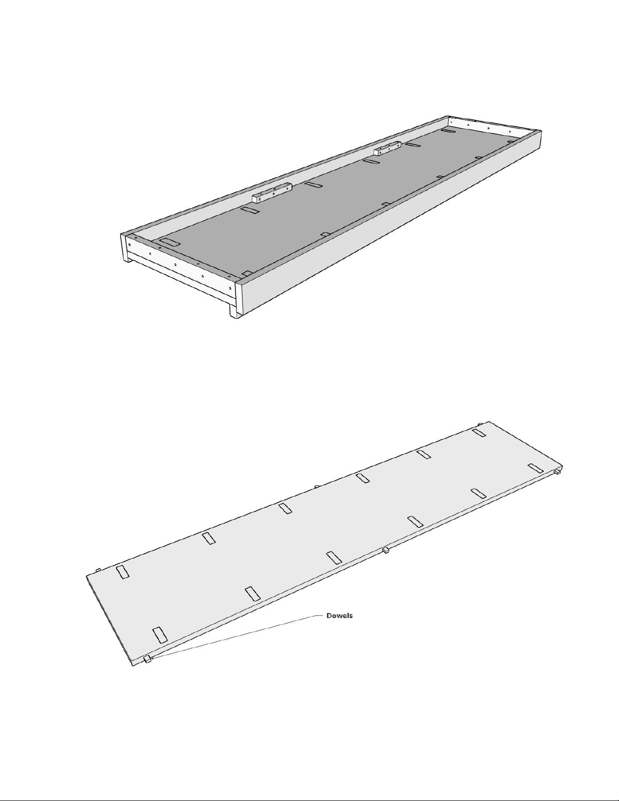
○ Bore hole for dowels to locate headboard.
○ Broke over edges
○ Sanded with to 220 grit (prep for finish)
● (C) Headboard
○ Cut to width and length
○ Edge band edges
○ Bore holes for dowels
○ Broke over edges
○ Sanded with to 220 grit (prep for finish)
● (D) Top Panel
○ Cut to width and length
○ Mortise dowel holes
○ Edge band edge
○ Broke over edges
○ Sanded with to 220 grit (prep for finish)
● (E) Top Facia
○ Cut to width and length
○ Mortise dowel holes
○ Edge band edges
○ Broke over edges
○ Sanded with to 220 grit (prep for finish)
● (F) Bottom Rear Base
○ Cut to width and length
○ Edge band edges
○ Broke over edges
○ Sanded with to 220 grit (prep for finish)
● (G) Bottom Kick
○ Cut to width and length
○ Edge band edges
○ Broke over edges
○ Sanded with to 220 grit (prep for finish)
● (H) Header Cleats
○ Cut to width and length
○ Broke over edges
○ Pre-drilled 9 holes
● (I) Header Stop
○ Cut to width and length
○ Broke over edges
○ Pre-drilled and countersunk 5 holes

Step 2: Build the Header
Using the (D) Top Panel, (E) 2 - Top Facia and, 2- (H) Header Cleats and (J) Support Cleats assemble the
Header.
2-1 Insert 3 dowels on each side of the Top Panel.
Figure 2-1

2-2 Attach the Top Facia to the Top Panel with Glue and 6 -1 1/2” Pocket Screws. Run the bead of glue along
the front edge of the Top Panel. Top Facia will overlap the lower side of the Top panel by ½” (see figure 2-2)
Figure 2-2
2-3 Attach the Back Facia to the top panel with Glue and 6 - 1 ½” Pocket Screws as in Step 2-2.
Figure 2-3

2-3 Attach the Header Cleats with glue and 4 - 2” screws (supplied) on each end. Flush the cleats with the
edge of the Top Facia (see figure 2-2)
Figure 2-4
2-4 Attach the Header Stop to the underside of the Header toward the front. Attach with 1 ½” screws.
Figure 2-5

2-5 Add two Support Cleats to the back side of the assembly. Position them by measuring from the Header
Cleat. 20” for king, 16” or queen, 15” for full, and 12” for twin. Glue and secure with 6 - 1 ¼” screws on each
cleat.
Figure 2-6
Your header is now complete!

Step 3: Finish all wood components
-Finish both sides of all components.
Tip: By placing pieces like the verticals, headboard and header on legs made from scrap material, you can
finish both sides at the same time and save time flipping.
Installing The Springs
Video: Adding Springs
NOTE: Some models may have the correct number of springs already installed. Check the chart and if your
bed already has them installed then skip this section.
1-1. The Number of springs in the Lift Mechanism will vary by size and application of the Murphy Bed. Check
chart below.
SPRING APPLICATION CHART
Please Note: These are recommendations only. Actual number of springs required will depend on the total weight of the bed face unit including the
mattress
and all bedding
BED SIZE
STANDARD FACE (NO DESK)
STANDARD FACE (ADDED DESK)
Single/Twin
4 Springs Vertical (3 Horizontal)
5 Springs Vertical (4 Horizontal)
Double/Full
5 Springs Vertical (4 Horizontal)
6 Springs Vertical (5 Horizontal)
Queen
6 Springs Vertical (5 Horizontal)
7 Springs Vertical (6 Horizontal)
King
8 Springs Vertical
9 Springs Vertical
After you have completed installing and checking the operation of your bed, you may find it necessary to add or remove springs to achieve the correct
lift effort of between 5 to 10 pounds.
1-2. There are nine locations for springs. If the bed requires an even number of springs, do not use the center
hole (#5 from the top). If the bed requires an odd number of springs, start with the center hole (#5 from the top)
and work outward in both directions evenly.
1-3. Hook the springs so the open ends are
facing outward. You may have to gently pry up
the tension arm and slide the spring under and
snap them into place in the proper hole,
matching the same numbered hole from the
top of the mechanism back plate. You should
have an equal number of springs on each side of
the center hole.
1-3. Repeat for the other Lift Mechanism.
Use the same number of springs and the same layout on both Mechanisms

Mounting Lift Mechanism
Video: Mounting the Lift Mechanism
NOTE: Some models may have the Lift Mechanism already
mounted to the verticals. If this is the case with your
Murphy bed than you can skip this section.
2-1. The left and right Lift Mechanism hole pattern will line
up with the hole pattern on the Side Panels (B). The bolts
will be fed through the side that has the counter sink holes
drilled.
2-2 Hole A will not have a standard nut. It is either a
threaded hole or it will use a disk like bolt “Arm Lock Stop”.
Get Hole A started.
2-3 Insert the bolt in the other holes and loosely tighten
onto the nuts.
2-4. Once all Bolts and Nuts have been started, tighten all
of them.
Assemble the Bed Cabinet
Video: The Cabinet Part 1
● If possible, the Bed Cabinet should be
assembled in the room where it will be
used.
● Be sure Lift Mechanisms are securely
installed.
Headboard and Top Panel Installation
On a soft surface like a blanket lay out the
verticals.
3-1. Insert the headboard dowels into the
ends of the headboard (two on each side). No
need to measure, The dowels will align the
headboard to where it needs to be. With the
pocket screw holes facing toward the back,
insert the headboard dowels into the side of
the verticals.

3-2. Lay the verticals in the floor with the mechanism facing up and the foot of the bed toward the wall.
3-3. Place the dowels in the end of the headboard into the dowel holes in the vertical making sure the
headboard screw pockets are facing toward the back and the finished edge of the headboard is facing what
would be up (with lying on the floor finish edge will be away from the wall)
3-4. Secure headboard to the verticals with 1 ½” screws (4 each side).
3-5. Carefully rotate the headboard and the one vertical so that the other end of the headboard/dowels can be
inserted into the second vertical. The unit should now be face down.
3-6. Secure this other end of the headboard to the verticals with 1 ½” screws (4 each side).
Top Panel
3-7. With the bed still face down on the floor attach the top panel. Top panel should be flush with the top of the
verticals and the front.
3-8. Secure each side with five 1-½” screws. 3-3.

STOP IF YOU HAVE LIGHTS
Video: Lights
If you have lights, you will want to make sure your
wiring and control box is in place.
L-1 Mount control box to the back of the
headboard using 1-½” screws. Mount this
centered and toward the bottom of the headboard.
L-2. Mount the Touch Plate to the top/back of the
headboard, centered, using a ¾” screw.
Note: drawing shows a knob instead of a
plate. We now use a touch plate.
L-3. Run the single wire from the control box with
Eyelet to the Touch Plate, and connect it with a ¾”
screw.
NOTE: If you have Outset lights there will be
an extra single wire connected to the back of
the Touch Plate. This wire will be routed to the
second Touch Plate Location. If there are no
bookcases the location will be on the side of
the murphy bed. If you have bookcases, the
second Touch Plate location will vary
depending on the type of bookcase you have.
L-4. Plug the control box into a wall outlet.
L-5. Plug the female wire coming out of the control box into the extension cord.
NOTE: With lights on the inside there will be a small control box inline on the extension cord.The small
control box will be attached to the frame later. If your lights on Outset (designed to overhang on the
outside of the cabinet, you will have a standard light duty extension cord.
L-6. Plug the other side of the extension cord into the lights.
L-7. With a hammer, carefully tap the extension into the groove on the back side of the Side Panels. Lay the
cord flat in the groove without any twist.
NOTE: Some pre-installed models may already have the cord installed in the groove.

BACK TO REGULAR INSTRUCTIONS
Video: Cabinet part 2
Stand the unit up and into its approximate place in the room. Check that the cutout made to clear your
base molding is sufficient. If not make the height it needs to be. Lay the unit back down on the face,
and adjust the cutout.
Bottom Rear Base and Bottom Kick
Bottom Rear Base and Bottom Kick will be the same width (4”) Some drawings may show them different sizes.
If you have added base molding is base molding may be attached to the Front Bottom Kick as in this example
3-9 Prep the Bottom Rear Base and Bottom Kick by adding 2 brackets on each end.
(NOTE: Some models this step may be done for you or you may see where the brackets were once put
on)
Lay both Bottom Rear Base and Bottom Kick face down on a clean soft surface. Flush the two brackets on
each end (about ½”-¾” from the top and bottom edge). Secure with ¾” screws.
(NOTE: Face will be the best side. If you can not tell which side is the best then it will not matter.)
3-10. Attach the Bottom Rear Base. Both the Bottom Rear Base and Bottom Kick will be the same height. You
may want to use the better one for the front Bottom Kick. With the brackets facing toward the front, bring the
Bottom Rear Base into so that it clears any cutouts that were made for the base molding
3-11. Attach the Bottom Kick by setting it back 1” from
the front of the Side Panels. These brackets will face
the wall/inside. Secure with ¾” screws.
Special application: If you have added base
molding, the Bottom Kick may be attached to that
base molding and may not have the 1” set back. Also in some cases the Bottom Kick will be replaced
by added base molding.
NOTE: The small control box will be just sitting there and will be attached to the frame later.

Attach Bed Cabinet Securely to Wall
Video: Attaching to wall
4-1: Find Studs
Prior to placing cabinet against the wall, locate 3 studs (you may only find 2 on a twin size) or other wall frame
members at the level of the Top Panel (top of bed). Alert: The cabinet must be secured to studs or other wall
structural members or injury and damage could occur. If the wall is not a wood stud wall, use metal stud
screws, toggle bolts or concrete expansion bolts if necessary.
Tip: for help finding studs there are several websites of video available online, just do a google search. One
example: https://www.lowes.com/n/how-to/how-to-find-studs-in-walls
4-2: Attach to wall
Now that the cabinet is square and
plumb, pre-drill a hole in that
backboard of the Top
Panel/header at the stud
location using a 3/16” drill bit.
Fasten to wall using 3” screws.
Repeat this for two other stud
locations.
If the wall is CONCRETE,
MORTAR OR BRICK
Construction, use masonry
screws:
Drill three pilot holes through the
rear rail of the bed header into the
wall for a twin or full and four for a
queen size bed. Using a 5/32”
concrete drill bit, drill through the
pilot holes into the wall 2” deep.
Anchor the bed by screwing 3/16 x
2 ¼” masonry screw through the
rear rail of the bed header into the
wall.

Assemble the Face
Lock the arm into place
Videos: Locking Spring and Frame Bolts and Straps
Caution: If possible have a helper assist in the setting of the mechanism and loading of the bed face panel. DO
NOT reach behind the tension arm when you are doing the setting procedure. To avoid reaching behind the
Tension Arm, use a pencil or screw driver to move the Arm Lock into place.
Holding one foot against the bottom front
edge of the side panel and using the
“Tension Arm Lever Tool”, pull the tension
arm out until you can set the arm lock to
the hex nut at the hole A (see drawing 13.).
This is the hex nut at the top front corner of
the mechanism.
Tip: If you set the “Arm Lock” on top of
the bolt before you pull the Tension
Arm back it will fall into place. Do not
put your fingers back there to while pulling it back!
5-1: Insert a Allen Head Bolts through Hole #1 (This
hole should be the one about 6 3/4” from the end of side
frame) on both left and right side frames (see Drawing).
NOTE: On some Models this Allen Head Bolt may
already be installed.
5-2 On each side, install 5/16“ (M8x20mm) Hex Head
Bolts from the outside of the frame through Hole #3.
Only thread the nut until it is flush with the Nut end. Do
not tighten.
Other manuals for DIY Alpha Murphy Bed
1
Table of contents
Other WWBeds Indoor Furnishing manuals
Popular Indoor Furnishing manuals by other brands

VECELO
VECELO KHD-XF-MR01-BLK Assembly instructions

Steelcase
Steelcase Norfolk II Modular Credenzas manual

Manhattan Comfort
Manhattan Comfort 222BMC1 quick start guide

Novellini
Novellini Sole manual

P3 International
P3 International Night Colors P4720 Specifications

Eurobib Direct
Eurobib Direct Malmo E37379 Assembly guide