WWBeds DIY Alpha Murphy Bed User manual

DIY Alpha Murphy Bed
(Vertical Pre-Cut Version)
Assembly Instructions
Questions call 501.753.9699
Designed to exceed International ISO 9002
Standards for Residential Specifications
Revised 5/20/2017

Table of Contents
Step 1: Check Your Components
Hardware
Single/Twin
Full/Double
Queen
What we have done for you!
Step 2: Build the Header
Step 3: Finish all wood components
Step 4: Install the springs on the Lift Mechanism
Step 5: Assemble the Bed Cabinet
Step 6: Attach Bed Cabinet Securely to Wall
Step 8: Install the Bed Face Panel Unit
Lights
Step 8: Install Handle = Legs - Mechanism Covers - Mattress
Complete Bed Assembly

Step 1: Check Your Components
Thank you for your purchase of this DIY Murphy bed. We try to make this projects as easy as possible for you.
Take a minute and check your contents.
Hardware

Single/Twin
Overall Cabinet Dimensions
Mattress Size: 39” x 75” (12” Max Thickness) 44 ½”w x 85 ¼”h x 16”d (Projection from wall: 85”)
Qty.
Description
Width
Length
☑
2
(A) Bed Face Panels
21 ¼”
77 5/16
2
(B) Verticals
16”
85 1/4
1
(C) Headboard
14 ¼”
43
1
(D) Top Panel
14 ½”
43
1
(E) Top Facia
2 ¾”
43”
1
(F) Bottom Rear Base
6”
43”
1
(G) Bottom Kick
4”
43”
2
(H) Header Cleats
1 ½”
14 ½”
1
(I) Header Stop
1
43
8
Brackets
Various
¾” screws
4
Hardwood Dowels
18
1 ½” screws
10
1 ¼” finish nails
16
2” Screws
3
3” Screws
6
Dowels

Full/Double
Overall Cabinet Dimensions
Mattress Size: 54” x 75” (12” Max Thickness) 59 ½”w x 85 ¼”h x 16”d (Projection from wall: 85”)
Qty.
Description
Width
Length
☑
4
(A) Bed Face Panels
14 ⅜”
77 5/16
2
(B) Verticals
16”
85 1/4
1
(C) Headboard
14 ¼”
58”
1
(D) Top Panel
14 ½”
58”
2
(E) Top Facia
2 ¾”
58”
1
(F) Bottom Rear Base
6”
58”
1
(G) Bottom Kick
4”
58”
2
(H) Header Cleats
1 ½”
14 ½”
1
(I) Header Stop
1
58
8
Brackets
Various
¾” screws
4
Hardwood Dowels
18
1 ½” screws
10
1 ¼” finish nails
16
2” Screws
3
3” screws
6
Dowels

Queen
Overall Cabinet Dimensions
Mattress Size: 60” x 80” (12” Max Thickness) 65 ½”w x 90 ¼”h x 16”d (Projection from wall: 90”
Qty.
Description
Width
Length
☑
4
(A) Bed Face Panels
15 ⅞”
82 5/16”
2
(B) Verticals
16”
90 ¼”
1
(C) Headboard
14 ¼”
64”
1
(D) Top Panel
14 ½”
64”
2
(E) Top Facia
2 ¾”
64”
1
(F) Bottom Rear Base
6”
64”
1
(G) Bottom Kick
4”
64”
2
(H) Header Cleats
1 ½”
14 ½”
1
(I) Header Stop
1
64
8
Brackets
Various
¾” screws
4
Hardwood Dowels
18
1 ½” screws
10
1 ¼” finish nails
16
2” Screws
3-4
3” Screws
6
Dowels

What we have done for you!
● 4-(A) Bed Face Panels
○ Cut to width and length
○ Edge band edges (Top and left for left pane, top and right on right panel and top on center panels)
○ Broke over edges
○ Sanded with to 220 grit (prep for finish)
● 2-(B) Verticals
○ Cut to width and length
○ Edge band edges (Front edge)
○ Bore the 5 holes on each for mechanism
○ Countersink each hole
○ Bore hole for dowels to locate headboard.
○ Broke over edges
○ Sanded with to 220 grit (prep for finish)
● (C) Headboard
○ Cut to width and length
○ Edge band edges
○ Bore holes for dowels
○ Broke over edges
○ Sanded with to 220 grit (prep for finish)
● (D) Top Panel
○ Cut to width and length
○ Mortise dowel holes
○ Edge band edge
○ Broke over edges
○ Sanded with to 220 grit (prep for finish)
● (E) Top Facia
○ Cut to width and length
○ Mortise dowel holes
○ Edge band edges
○ Broke over edges
○ Sanded with to 220 grit (prep for finish)
● (F) Bottom Rear Base
○ Cut to width and length
○ Edge band edges
○ Broke over edges
○ Sanded with to 220 grit (prep for finish)
● (G) Bottom Kick
○ Cut to width and length
○ Edge band edges
○ Broke over edges
○ Sanded with to 220 grit (prep for finish)
● (H) Header Cleats
○ Cut to width and length
○ Broke over edges
○ Pre-drilled 9 holes
● (I) Header Stop
○ Cut to width and length
○ Broke over edges
○ Pre-drilled and countersunk 5 holes

Step 2: Build the Header
Using the (D) Top Panel, (E) Top Facia and, 2- (H) Header Cleats assemble the Header.
2-1 Most versions will have holes in the Top Facia and Top Panel to insert dowels. Insert 3 on each side of the
Top Panel.
2-2 Attach the Top Facia to the Top Panel with 1 ¼” finish nails (not supplied). Top Facia will overlap the lower
side of the Top panel by ½” (see figure 2-1)
Figure 2-1
2-2 Attach the Back Facia to the top panel. Pre-drill holes using ⅛” bit about every 8-10”. Use a countersink so
that the screw will be slightly recessed when inserted. Insert 2” screws supplied.

2-3 Attach the Header Cleats with 4- 1 4” screws (supplied) on each end. Flush the cleats with the edge of the
Top Facia (see figure 2-2)
Figure 2-2
2-4 Attach the Header Stop to the underside of the Header toward the front. Attach with 1 ½” screws.
Your header is now complete!

Step 3: Finish all wood components
-Finish both sides of all components.
Tip: By placing pieces like the verticals, headboard and header on legs made from scrap material, you can
finish both sides at the same time and save time flipping.
Install the Murphy Bed
Step 4: Install the springs and the Lift Mechanism
4-1: The left and right mechanism hole pattern will line up with the hole pattern on the Side Panel (B). The
bolts will be fed through the side that has the counter sinks drilled.
4-2 Hole A will not have a standard nut. It is either a threaded hole or it will use a disk like bolt “Arm Lock
Stop”. Get Hole A started.
4-3 Insert the bolt in the other holes and loosely tighten onto the nutes.
4-4 Once all are in place securely tighten using the Allen Wrench provided and a ½” wrench.
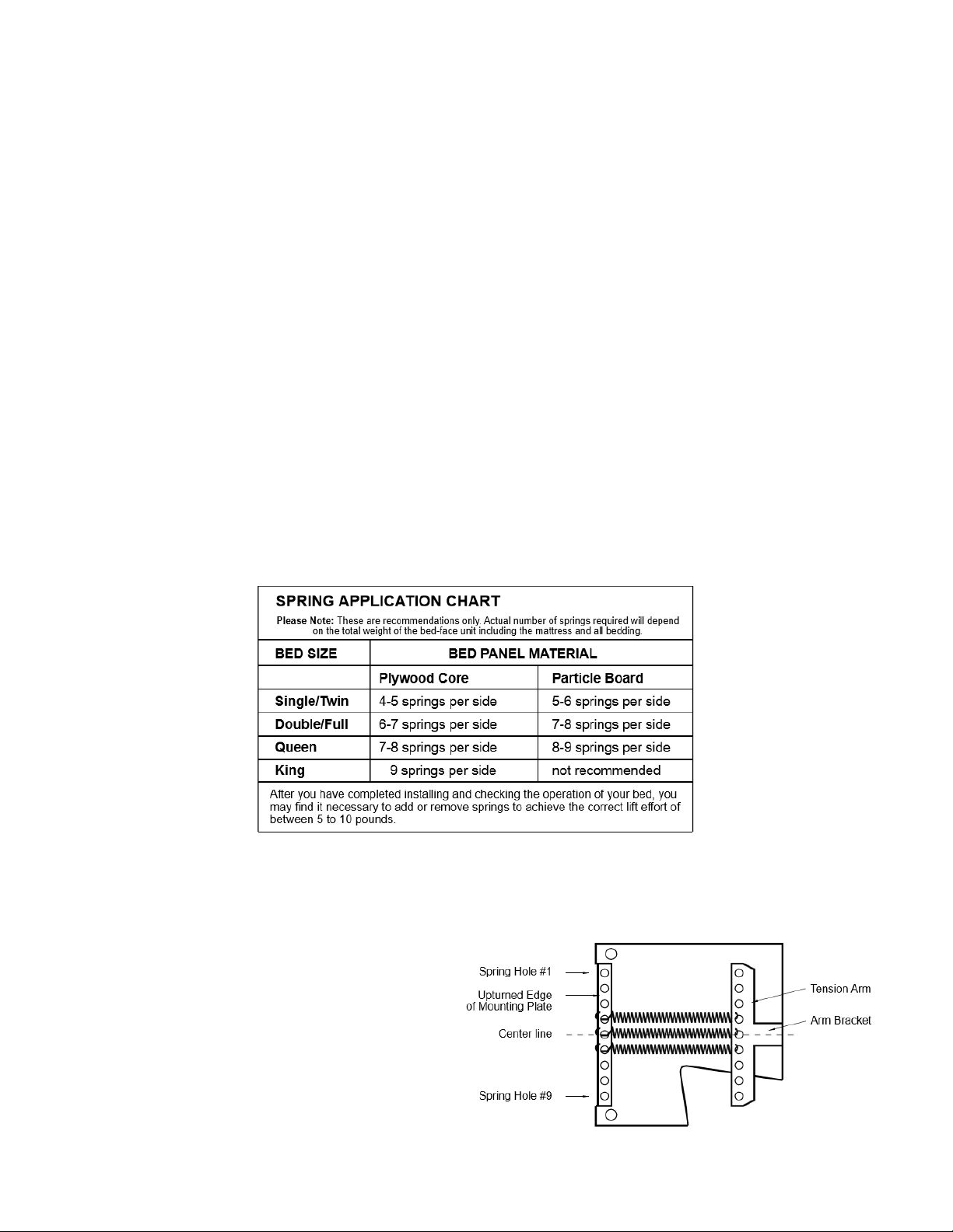
There are nine locations for springs. If the bed requires an even number of springs, do not use the center hole
(#5 from the top). If the bed requires an odd number of springs, start with the center hole (#5 from the top) and
work outward in both directions evenly.
Hook the springs so the open ends are facing
outward. You may have to gently pry up the
tension arm and slide the spring under and snap
them into place in the proper hole, matching the
same numbered hole from the top of the
mechanism back plate. You should have an equal
number of springs on each side of the center
hole.
Use the same number of springs and the same
layout on both the left and right mechanisms.

Step 5: Assemble the Bed Cabinet
The following installation will be done with the bed face down on the floor.
Place the verticals finished edge down and dowel holes toward the inside on a clean floor. You may even lay a
soft blanket down to protect the finish from being scratched.
Headboard installation
5-1: Insert the headboard dowels into the ends of the headboard (two on each side). No need to measure
we’ve taken that step out of you. With the pocket screw holes facing toward the back, insert the headboard
dowels into the side of the verticals. Secure with 1 ½” screws (4 each side).
5-2: Attach header as shown in Drawings 6 & 7. Be sure back edge of the header is flush with back of Side
Panels and the top. Attach with 1 ½” supplied screws.
Lights
If you don’t have lights skip to step 5-3
L-1. Using the BLUE assembly book, assemble the bed
components.
NOTE: STOP ON STEP 7 WHILE BED IS STILL LYING ON
FACE.
L-2. Mount the control box to the head side of the metal
frame on the inside. Attach with 2- 1 ½” screws. make sure
the arrow is facing up.
L-3. Mount the touch sensor plate on the center of the
headboard with one ¾” screw provided. Find the touch sensor
wire on the control box (small thin wire). Put the other ¾”
screw through the eye connector of the touch wire and into
the touch sensor plate. (NOTE: Some models may have a
brass plate. That should be attached from the
back/top/center of the headboard.
L-4. Run the extension cord up the groove in the vertical,
making sure the female end is at the top of the vertical and
there is about 3” of slack at the top. Attach the other wires:
from the box to the white cord, and from the box to the wall.
L-5. Plug the white cord into the first light. Plug the two lights together

5-3: Stand the bed up in place. Use Angle Brackets to assemble Bottom Rear Base and Bottom Kick in
position shown in Drawings 6 & 7. Use two Angle Brackets on each end. Attaching using supplied ¾” screws.
NOTE: The Bottom
Rear base can be
moved closer to the
front if there is a
cutout for base
molding on the back
of the verticals.
Drawing 7
Brackets may be different than used in the drawing

Step 6: Attach Bed Cabinet Securely to Wall
(Note: For your header I changed the bracket shown to mount to wall to a solid strip (see step 6-2)
We cut out for your base molding so you don’t have to remove base molding off the wall. If our cutout was not
large enough more may need to be done. Use a jig saw to perform this task.
6-1: Find Studs
Prior to placing cabinet against the wall, locate 3 studs or other wall frame members at the level of the Top
Panel (top of bed). Alert: The cabinet must be secured to studs or other wall structural members using
L-Brackets. If the wall is not a wood stud wall, use metal stud screws, toggle bolts or concrete expansion bolts
if necessary.
6-2: Attach to wall
Now that the cabinet is square and plumb, pre-drill hole in that backboard of the header at the stud
location and 3” screws. Repeat this for two other stud locations. (see Drawing 9. but instead of brackets
you’ll drill through the back board on the header).
Note: change in header design. There is now a backboard on there header instead of the brackets.

Holding one foot against the bottom front edge of the side panel and using the 13” (330mm) PVC tube, lever
the tension arm out until you can set the arm lock to the hex nut at the hole A (see drawing 13.). This is the hex
nut at the top front corner of the mechanism.
Tip: If you set the “Arm Lock” on top of the bolt before you pull the Tension Arm back it will fall into place. Do
no put your fingers back there to while pulling it back.!
Caution: If possible have a helper assist in the setting of the mechanism and loading of the bed face panel. DO
NOT reach behind the tension arm when you are doing the setting procedure.
Step 8: Install the Bed Face Panel Unit


7-1 Lay the Bed Face Panels down on a non-scratch surface such as a carpet or blanket. Make sure they the
better side is face down and banded edges facing out and toward the foot of the bed.
(Note: both sides are finished but there usually is a better side. Better side is facing down. Also there may be
edges that are raw with the plywood exposed. Make sure all these edge are on the inside and down.
7-2: Completely assemble the 4 Frame Sections with the corner brackets and the
3/16”x1/2” (M5x12mm) black bolts provided (if you don’t have space in another part of the room, then you
assemble this section right on top of the face panels)
. Refer to Drawing 12 to properly place
the leg stops at outer right and left bottom holes at the foot of the bed frame.
7-3: Position the bed frame on the bed face panels. With the Head Frame section
flush with the head end of the Bed Face Panels. Refer to Drawing 10. Carefully
attach the Bed Frame so it is centered on the Bed Face Panels; you will have
approximately 15/16” (24mm) space from the bed frame to the panel edges right and
left and at the bed foot.
Note: It is very important to have the Bed Frame centered on the Bed Face Panels.
Any error will be noticed in the vertical sight lines when the bed is closed.
7-4: Three steel stiffeners are provided for all beds (5 for King). These notched stiffeners
should be located and attached to divide the Bed Face length into four equal
sections. Use caution not to damage raised panels by putting screws in recessed
areas. Note: King Beds have 5 stiffeners (see diagram on pg. 6 for placement).
7-5: Attach the Nylon Web Strap approximately 18” (460mm) down from the foot of the
bed and 6” (150mm) in from the sides, for tucking in sheets. The Straps help secure
the mattress in the vertical position (see drawing above
.
7-6: From hardware card 2, insert a Allen Head Bolts through Hole #1 (6 3/4” from end of side frame) on both
left and right side frames (see Drawing 14).
7-7 Also Inserted two 5/16“ (M8x20mm) Hex Head Bolts from the outside of the frame through Hole #3. We
have left these loose.
7-8 Stand the Bed Face Panel in vertical position between the tension arms, lift evenly until the bolt in Hole #3
drops in the slotted end of each tension arm. Gently tilt the bed face toward you until the Allen Bolts in Hole #1
are completely seated in the bottom notch of the tension arms. Insert the remaining 5/16” (8mm) Hex Head
Bolts through tension arms into Holes #2 and fasten with 5/16“ (8mm) Nylock Nuts; securely tighten these and
the nuts on Hole #3.

7-9 When all bolts are securely tightened, you may tilt the panel outward to approximately 45 degrees to
release the arm locks. You will hear a click as they disengage.
Caution:
Hold the Face Panel securely, Do Not let it slam shut. Balance is not achieved until the mattress is loaded in
the bed.
Leveling of the bed cabinet is essential. Check the level both side to side and front to back. Proper leveling will
facilitate proper closure and exact sight lines of the fit of the Face Panel to the Cabinet.

Step 8: Install Handle = Legs - Mechanism Covers - Mattress
8-1 Position and secure handles for ease of operation. Measure down approximately 36” (914mm) from the
panel top to the top of the handles.
8-2 Install legs with the washers on the inside of the Rails and the Nylon washer on the outside. Tighten nut to
have a small amount of friction when leg assembly is rotated from the up to down position.
8-3 Install leg connector rod between legs and secure with 1/4”x1 1/4” (M4x32mm) Hex head bolts and star
washers. Be sure they are securely tightened so not to become loose.
8-4 Install the mattress and secure with previously installed Nylon Straps.
8-5 Snap the powder coated steel mechanism covers in place - secure with #8x1 1/4” (M4x32mm) black wood
screws through the standoff on the backer plate

Complete Bed Assembly
Follow up to Initial Assembly
Check that the Bed Cabinet is level and square so the Bed Face has equal clearance of the Cabinet on both
sides, top to bottom. If the Cabinet is leaning to one side, nudge it at the floor level. If the top is uneven, place
shims under the Side Panels. If bed is too heavy to operate easily or slams shut, remove the Bed Face Panel
and add or subtract springs. At this time, you may decide to use one more or less spring(s) on the left or right
side Lift Mechanism.
Revised 5/20/17
Other manuals for DIY Alpha Murphy Bed
1
Table of contents
Other WWBeds Indoor Furnishing manuals
Popular Indoor Furnishing manuals by other brands

Wampat
Wampat W04L3181N Assembly instructions

Forte
Forte CLFT235 Assembling Instruction

Furniture of America
Furniture of America CM3194T Assembly instructions

Furniture of America
Furniture of America CM3577T Assembly instructions

DETAIL
DETAIL Forest DHS339 quick start guide

Steelcase
Steelcase Ology Assembly Directions