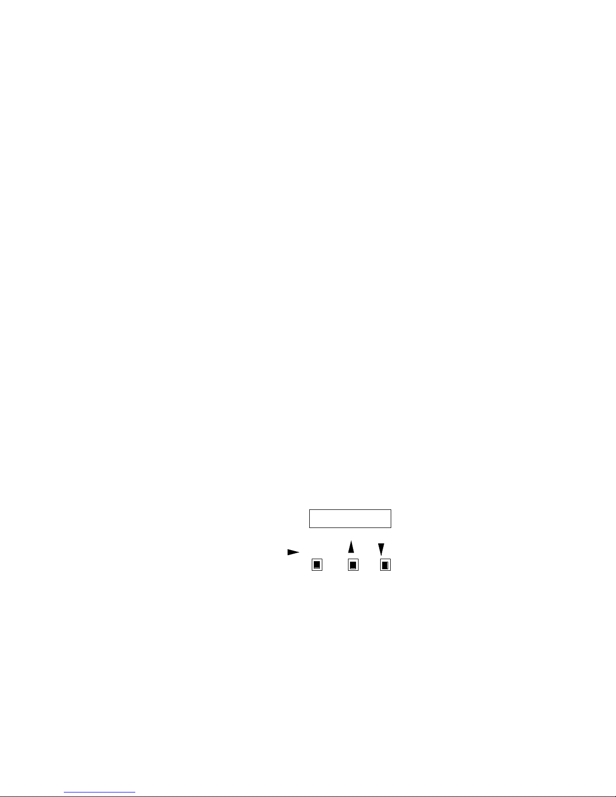
Wybron II User manual

Power Supply User Manual

2
19000 – 24-Way Coloram Power Supply (600 watts)
19012 – 12-Way Coloram Power Supply (300 watts)
19060 – 6-Way Coloram Power Supply (150 watts)
Software versions: PS24 V3.0, PS12 V3.0, PS6 V3.0
Manual revision: April 14, 2003
CONTENTS
Safety Information................................................................ 3
Introduction........................................................................... 4
The Coloram II System......................................................... 4
The Coloram II System Components ................................... 5
Color Changers and Other Components.............….... .. 5
Power Supply.......................................................... .... .. 6
Cables..................................................................... .... .. 6
The Coloram II Power Supply Menu............................. .... .. 7
Menu Tree............................................................... .... .. 7
Menu Details........................................................... .... .. 7
Error Messages....................................................... .... .. 8
Installing/Connecting the Coloram II Power Supply............ 15
Head-Feet Restrictions....................................................... 17
Mounting and Installation Accessories ............................... 18
Equipment Compatibility..................................................... 21
Cables................................................................................ 21
Specifications ..................................................................... 22
Software Version Changes ................................................ 23
Parts list ............................................................................. 23
Warranty information .......................................................... 25

3
SAVE THESE INSTRUCTIONS
READ AND FOLLOW ALL
INSTRUCTIONS
IMPORTANT SAFETY INSTRUCTIONS
This manual gives step-by-step instructions for
preparation, setup and operation of the Coloram II Power
Supply.
There is a potential risk of fire, electric shock or injury to
persons if the product is not used as instructed.
This product is to be used in an indoor environment only
and is not intended for residential use.

4
Introduction
The Coloram II System consists of scrolling color changers, mixing color changers,
dowsers, other products and power supplies in a wide range of models offering ease of
setup and use. Its color changing capability and DMX compatibility affords the designer
wide capability and versatility. The lightweight color changers slide easily into the gel
frame holder of the light fixture. The compact power supplies attach easily to the truss of
the lighting rig or mount into a 19-inch rack.
The Coloram II System
The Coloram II System consists of one or more Color Changers or other components
and a remote power supply. The DMX512 control signal from the lighting board is
connected to the power supply and can continue on to more Coloram II Power Supplies
or other DMX-controlled devices. The power supply sends both power and control
signal on a single cable eliminating the need for a separate power cable for each color
changer.
The Coloram II System also allows you to control the color changer fan speed via one
or multiple DMX channels on the lighting console.
The Coloram II System is equipped with the Intelligent Diagnostic System (IDS). Status
information is sent from each of the Coloram II Color Changers to the Coloram II Power
Supply.
Caution: The Coloram II System is not compatible with the Forerunner
System. Do not connect Coloram II Color Changers to Forerunner Power
Supplies, or Forerunner Color Changers to Coloram II Power Supplies.
Damage from such action will not be covered by the Coloram II or
Forerunner warranties.

5
DMX CONSOLE
DMX512
DMX Control console
AC Power
Goboram II Gobo Chgr
Coloram II
Color Changer
To additional
Color Changers
or Gobo Chgrs
Coloram II
Power Supply
To additional
Coloram Power Supplies
Buffered
DMX512
To additional
Color Changers
or Gobo Chgrs
To additional
Color Changers
or Gobo Changers
Coloram II
Color Changer
Eclipse
Dowser
The Coloram II System Components
Color changers and other components
The color changers set the position of the gelstring via a signal from the lighting
console. The control signal and DC power (24 VDC) are both supplied in one cable
connecting the color changers to the power supply.
Other Coloram II products include the Eclipse Dowser, the CXI Color Changer and
others. Other products are continually being added to the Coloram II family to expand its
capabilities.
Refer to the user manual of the various Coloram II products for detailed operating
information on those products.

6
Power Supply
The power supply converts the DMX512 signal level from the lighting console into
Coloram I/Coloram II control signal which it then sends to each color changer along with
24 volts DC. The power supply features a DMX bypass relay to pass the DMX signal to
the DMX output connector in the event of AC power loss.
The power supply features an 8 character LED display and three selector buttons. This
user interface is used to select the starting DMX channel, set operating modes, send
remote commands to the color changers and view color changer status.
Coloram II Cable
The Coloram II Cable connects the Coloram II Power Supply outputs to the Coloram II
Color Changers or other products and provides them with power and control signal. The
Coloram II Cable uses 4-pin XLR connectors on either end and consists of two 14 AWG
conductors and a 22 AWG twisted, shielded pair.
Note: Colroam II Cable is used in the Coloram II System and in the Forerunner System.
It may be referred to as either Coloram cable or Forerunner cable.
The Coloram II Power Supply menu
This section describes the power supply menu.
The following diagram is the eight character display and the three push buttons:
/ENTER +_
DISPLAY
The following diagram is an overall view of the power supply menu structure:

7
XX UNITS SETUP OPTIONS
SHUTDOWN
SEND ?SEND ?POS ? XXX
COMMANDS
YES NO YES NO +-NORM
LOW
OFF NORM LOW
DISP ?
DEC
%
HEX
1 -- X
DMX OK
*ALERT*
CHAN ?MODE ?JTTR ?
TBCK ?
Chan 001 Tbck OFF Jttr OFF
Mode CR2
ON OFF ON OFF
+-
INCREMENT
DMX NO DMX
PROCESSING
NO DMX
PROCESSING
NO DMX
PROCESSING
ROLLCALL
INTRO
Increment
DMX
Increment
1 of X
DMX 001
1 OF 1ON OFF
Foff OFF
Foff ?
DMXF ?
OFF
ONE
BLK
DMXF OFF
CR2
CR1
Disp %
FChn XXX
FChn ?
+-
Run REG
Run ? xxx
REG
MIN
RESET ?
OK NO
Reset NO
DMX ALL
Re-Init POS 000 Fan LOW
Fan? LOW
Mtr NORM
Mtr ? LOW
Coloram IDENTIFY
POS 000DCV 24 Fan NORM Mtr NORM Ver x.x
CXI IDENTIFY
DCV 24 Fan NORM Ver x.x
OR ... GLA 0% GLB 0%
" "
" "
" "" "" "
" "
" "
" "" "
" "
" "
" "
" "
" "
" "
" "
" "
MEANS PRESS
MEANS PRESS
BUTTON
BUTTON
ALERT DETAILS
APPEAR HERE
" "" "
X ALERT
" "
" "
POWER-UP
SCREENS
RUN
SCREEN
LOOP
Menu Details
The following is an explanation of functions and optional settings which are accessed
via the various menus displayed.
POWER UP SCREENS
When you connect the power supply to AC power, the following screens will appear on
the display.
1. The INTRODUCTION screen will scroll through the software version and
other information.
2. The ROLLCALL screen shows when the power supply interrogates the
color changers and other components connected to the power supply. This is the
time the color changers "check in" with the power supply.

8
RUN SCREEN LOOP
The display alternates between three screens.
The first is "1 -- X" where X is highest DMX channel used by a color changer (or other
component) connected to the power supply. If talkback is ON, X will be the highest DMX
channel used by the talkback function.
The second screen is "DMX OK"if the DMX signal is being properly received. It is
"NO DMX” if the DMX signal is not being properly received.
The third screen is " *ALERTS* " if there are any alert conditions to report.
ALERTS / ERROR MESSAGES
The power supply will display "alert messages" indicating a condition a service person
may want to know about.
The alert messages and meanings are as follows:
Note: the "xxx" after each message is the DMX channel to which the message applies.
"Pstn xxx" -Gel position error -a difference exists between the commanded gel
position and the actual gel position.
"VDC xxx" -Color changer voltage is below 17 volts DC.
"Shut xxx" -Color changer reports a SHUTDOWN condition (will not respond to
position commands because the voltage dropped below 15 VDC).
"Drop xxx" -Color changer is disconnected and there is a loss of communication - it
previously reported a status but is no longer doing so.
"Motr xxx" -The color changer's motor cannot move the gel string.
"ChErr xxx" -There is a channel assignment problem with the color changer set to start
on channel xxx. For example, some of the multiple channels used by the
color changer fall past the last channel available on the power supply.
"Overload" -This is displayed when the power supply has not yet reached its current
limit, a unit "checks in" which has a current requirement at least 2 times
that of a Coloram II and the resulting total current load on the power
supply is over the power supply's limit. This last unit will remain checked
in. However, no more units will be allowed to check in.

9
It is important to note that if the power supply is at its current limit (but not
exceeded), it will not "check in" any other units and the "Overload"
message will not be displayed.
"DMX Chan"-This is displayed if the DMX source is sending less than 512
channels and the last DMX channel sent is less than the last
DMX channel in the power supply channel range.
"Fan Chan" -This is similar to the "DMX Chan" explanation above but applies to the fan
DMX channel or fan DMX channel block.
To read the above "alert messages", do the following:
1. When *ALERT* is being displayed, press
/Enter
. Then the number of
alert messages will be displayed.
2. As an example: "2 ALERTS" indicates there are 2 problems (alerts).
3. Press "t" button to get more information on the alerts.
4. As an example: "Pstn 001" indicates the head unit #1 has a position error.
5. Press
/Enter
to get information on other alerts.
6. Viewing the alerts in this manner also "clears them" unless the problem
currently exists.
XX UNITS
This is commonly referred to as the status menu. It displays the number of color
changers, CXIs and/or other Coloram II components connected the power supply.
Press [
-
]
DMX 001 -Pressing [
/Enter
] allows you to select the DMX channel of the color
changer or gobo changer which you wish to view the status of. Only channels with color
changers or gobo changers set to them will be displayed.
Press [
-
]
1 of 1-Pressing [
/Enter
] allows you to select a specific color changer or gobo
changer if more than one color changer or gobo changer is set to that channel.
Press [
-
]
For the Coloram II color changer:
ColoRAM -Indicates there is a color changer addressed to this channel.
[
/Enter
]

10
DCV 24.0 -This displays the DC voltage at the color changer.
[
/Enter
]
Pos 000 -This displays the actual position of the gelstring. If the color changer is
moving toward FL, an arrow pointing to the right (>) will be displayed. If the color
changer is moving toward 00, an arrow pointing to the left (<) will be displayed.
[
/Enter
]
Fan NORM -This displays the fan status; HI, LOW, or OFF.
[
/Enter
]
Mtr NORM -This indicates if the motor speed is set to normal or low.
[
/Enter
]
Ver x.x -This tells you the software version installed in the color changer set to the
channel you are looking at.
[
/Enter
]
Identify -Pressing [
-
] will cause the color changer, whose status you are viewing, to
initialize.
For the CXI color changer:
CXI -Indicates there is a CXI color changer addressed to this channel.
[
/Enter
]
DCV 24.0 -This displays the DC voltage at the CXI.
[
/Enter
]
GLA 0% -This displays the % position of gel string A (farthest from the mounting plate).
[
/Enter
]
GLB 0% -This displays the % position of gel string B (nearest the mounting plate).
[
/Enter
]
Fan NORM -This displays the fan status; HI, LOW, or OFF.
[
/Enter
]

11
Ver x.x -This tells you the software version installed in the color changer set to the
channel you are looking at.
[
/Enter
]
Identify -Pressing [
-
] will cause the color changer, whose status you are viewing, to
initialize.
For the Goboram II:
GoboRAM -Indicates there is a gobo changer addressed to this channel.
[
/Enter
]
DCV 24.0 -This displays the DC voltage at the gobo changer.
[
/Enter
]
Pos 000 -This displays the position of the gobo section channel. If the gobo changer is
moving the carriers toward FL, an arrow pointing to the right (>) will be displayed. If the
gobo changer is moving the carriers toward 00, an arrow pointing to the left (<) will be
displayed.
[
/Enter
]
Rot 000 -This displays the rotational position of the gobo. If the gobo changer is
rotating the carriers toward FL, an arrow pointing to the right (>) will be displayed. If the
gobo changer is rotating the carriers toward 00, an arrow pointing to the left (<) will be
displayed.
[
/Enter
]
Spin OFF -When the third control channel for this gobo changer has a level of 99 or
less, this display will tell you the continuous rotation option is off. When the third control
channel has a level of FL, the display will tell you the gobo is spinning counter clock
wise if the second control channel has a level of 00 - 49%. The display will tell you the
gobo is spinning clock wise if the second control channel has a level of 51% -FL. When
the third control channel has a level of FL and the second control channel has a level of
50%, the display will tell you the gobo is not spinning by showing HLD.
[
/Enter
]
Ver x.x -This tells you the software version installed in the gobo changer set to the
channel you are looking at.
[
/Enter
]

12
Identify -Pressing [
-
] will cause the gobo changer, whose status you are viewing, to
initialize.
SETUP
This menu is used to display and select the starting DMX channel as well as other
operating modes.
Pressing [
-
] at any of the following options will bring up a question mark (?) behind
the option. Pressing [ +] and [
-
] will increment and decrement numbers such as
channels or toggle options such as on or off. Pressing [
/Enter
] will confirm your
selection and the question mark will go away.
[
-
]
Chan 001 -This allows you to select the first channel of the DMX channel block which
the Power Supply will respond to.
[
/Enter
]
Mode CR2 -This selects original Coloram 1 (12 channel mode -CR1) or Coloram II (24
channel mode -CR2). This option must be set to CR1 to work with original Coloram I
color changers which have not had the Coloram II software upgrade.
[
/Enter
]
Tbck OFF -This option turns talkback to a remote status monitor on or off. Status of the
color changers or gobo changers will still be displayed in the status menu. If this is
turned on, the first channel of the power supply's DMX channel block is limited to 1, 4, 7,
10, 13, 16, etc.
[
/Enter
]
Jttr OFF -This option turns the jitter filter on or off. This option may be necessary for
AMX to DMX converters which can have LSB jitter.
[
/Enter
]
DMXF OFF -DMX fan control channel. This enables or disables the lighting console fan
speed control. This can be OFF (do not control the fans via a DMX channel), ONE
(select one DMX channel to control all the color changer fans connected to that power
supply) or BLK (select a BLOCK of DMX channels -one DMX channel for each channel
of the power supply (12 channels for a 12 way power supply).
If you use BLOCK, do not mix single channel Coloram IIs and multi-channel products
(such as CXI color changers). Also, if the CXIs or any other multi-channel components
are used, they must all be configured to use the same number of DMX channels.

13
The following two screens will be displayed only if the DMX fan option is turned on.
[
/Enter
]
FChn 025 -This allows you to set the DMX fan control channel (ONE or first channel of
the BLOCK) to any channel between, and including, 001 and 512.
[
/Enter
]
Foff OFF -When turned on, this feature allows you to turn the fans in the color
changers off from the lighting console. This is done by sending a level of 8% to the fan
control channel. This unusual level was chosen to minimize the probability of
unintentionally turning the fans off.
OPTIONS
This menu is where you select the power supply display mode.
Pressing [
-
] at any of the following options will bring a up a question mark (?) behind
the option. Pressing [+] and [
-
] will increment and decrement numbers or toggle
options. Pressing [
/Enter
] will confirm your selection and the question mark will go
away.
[
-
]
Disp %-This option allows you to select how the power supply will display position
information in the status menu and in the commands menu. The options are decimal (0
-255), % (0 - 100), or hex (0 - FF).
[
/Enter
]
Run REG -This option affects the main run screen which is displayed after initial power
up of the power supply. The purpose is to minimize the flashing display characters
which may be distracting if seen. When set to REG, the display will alternate between
the selected channel range, DMX OK or NO DMX, and *ALERT* if any alerts are
present. When set to MIN, the display will not alternate. You will see the display as
follows:
001 - - 048
If NO DMX signal is present, you will see the display (the first - changes to a + ) as
follows:
001 + - 048

14
If an alert has been triggered with the presence of DMX signal, you will see the display
(the second - changes to a + ) as follows:
001 - + 048
If an alert has been triggered without the presence of DMX signal, the display will look
as follows:
001 + + 048
[
/Enter
]
Reset: This option allows you to reset all parameters to factory default. This resets all
parameters found in the setup menu, the display to read out in %, and erases all color
changer/gobo changer status information.
COMMANDS
This is the menu you use to send local commands to the color changers and gobo
changers.
Pressing [
-
] at any of the following options will bring up a question mark (?) behind
the option. Pressing [ +] and [
-
] will increment and decrement numbers or toggle
options. Pressing [
/Enter
] will confirm your selection and the question mark will go
away.
[
-
]
DMX ALL -This will send commands to all color changers or gobo changers connected
to this power supply. Pressing [
/Enter
] allows you to select the DMX channel of the
individual color changer or gobo changer which you wish to send commands to.
Channels with color changers or gobo changers set to them will be indicated by an
asterisk.
[
-
]
Re-Init -This will cause the color changers or gobo changers to re-calibrate their
gelstrings or gobo carriers.
[
/Enter
]
Shutdown -This will shut down motor drive in the selected color changer or gobo
changer. The unit will not respond to position commands.
[
/Enter
]

15
Pos -This allows you to move the gelstring or gobo carrier independently from the
lighting console.
[
/Enter
]
Fan -This allows you to change the fan speed independently from the lighting console.
[
/Enter
]
Mtr -This allows you to limit the top speed at which the motor will run. This applies to
Coloram II.
Installing / Connecting the Coloram II Power Supply
To get your Coloram II Power Supply up and running, follow these hookup and checkout
procedures.
1. Mount the power supply
The Coloram II Power Supply is designed to be free standing, truss mounted, or
rack mounted.
The power supply comes with a mounting bracket which hooks over the pipe or
truss of your lighting rig and is then locked into place with a thumb screw. If you
have selected this mounting method, connect the power supply's safety cable by
clipping it around the pipe or truss.
The power supply can also be mounted into a 19" rack using the optional
Coloram II Power Supply rack mount kit. The rack mount kit will accommodate
two Coloram II Power Supplies side by side.
2. Connect the color changers to the power supply
Connect the color changers to the power supply using 4-pin Wybron DMX
power/signal cable.
Refer to the HEAD-FEET RESTRICTION section of the manual for details of the
length of cable runs.
Note: The Wybron DMX Cable has been specially designed to minimize voltage
drop -- use only Wybron supplied cable.

16
3. Connect the Power Supply to AC power
Plug the AC cord into a non-dimmed power circuit. The power supply
automatically accommodates 100 -132 VAC (50/60 Hz) or 170 -240 VAC (50/60
Hz).
Power at the Coloram II Power Supply is indicated by the red display which can
be viewed from the stage. Power is also indicated on the bottom of each color
changer by a red or yellow LED.
The connected color changers will automatically "check in" with the power supply
and "initialize" the gelstring installed by doing the following actions:
1. Moving the gelstring toward the last frame, in search of the long foil tag.
2. Turning around at the long foil tag and then searching for the short foil tag
at the beginning of the gelstring.
3. Stopping at the short foil tag and staying there if no DMX signal is present
or going to it's commanded position if DMX signal is present.
Note: It may take up to 30 seconds before all color changers start to initialize.
Upon power up, the power supply will scroll a short message which includes the
software version installed in it.The power supply will then initiate a "roll call"
which tells the color changers to "check in" and initialize the gel string.
Caution: Do not power the power supply from a dimmer. Severe damage
will result and is not covered by product warranty.
4. Set the Power Supply/Color Changer Channels
Each color changer is assigned a DMX address to which it will respond. Valid
DMX addresses are 001 -512.
First, set the first channel for the block of DMX channels selected for the power
supply. Then, set the color changer for the first, second, etc channel of that
block of channels.
For example, if you want a color changer to respond to DMX channel 105, first
set the power supply channel block to start on channel 105 and then set the color
changer to 1 which is the first channel in the block of power supply channels -
channel 105.
The block of channels varies with the power supply model. For the 24-way power
supply, the block is 48 channels. For the 12-way, it is 24 channels and for the 6-
way, it is 12 channels.
Set the power supply starting DMX channel by using the SETUP menu. If
talkback is enabled on the power supply, the starting power supply channels are
limited to 1, 4, 7, 10, 13, etc.

17
Fan speed (when enabled at the power supply) is remotely controlled with the
following DMX levels:
51% to 100% -- fan at normal (high) speed
0% to 50% -- fan at low speed
8% = fan off (when this function is enabled at the power supply)
Refer to the user manual of the various Coloram II products for detailed operating
information on those products.
The formula for calculating DMX channels is as follows:
Color Changer DMX channel = Color Changer channel + Power
Supply starting channel - 1
Example: Color changer DMX channel (221) = color changer channel (20) +
power supply starting channel (202) -1
Note:For the 24-way power supply, the Coloram II color changers can only be
addressed to the first 24 channels of the 48 channel block of the power supply.
Note: The color changers will not respond to the DMX signal until you return
in the "menu tree" to the RUN SCREEN loop.
5. Connect and set the DMX512 source
Connect the DMX512 signal source to the DMX input connector on the front of the
power supply using standard DMX cable. Valid DMX signal will be indicated by the
words "DMX OK" on the power supply display. The color changers will now position
their gelstrings according to their respective DMX signal levels.
Head-Feet Restrictions
The HEAD-FEET parameter is a method of accounting for the voltage drop in the
power/signal cable caused by the current drawn by each color changer.
To help understand this issue, think of it as water pressure (voltage) in a hose (cable)
where you have multiple water sprinkler heads (color changers). If the hose (cable) is
too long or you have too many sprinkler heads (color changers), the water pressure
(voltage) will be too low.
HEAD-FEET is defined as "the sum of cable lengths from each color changer to a single
power supply output".

18
Refer to the user manual of the various Coloram II System components for detailed
head-feet information on those products.
"Head-Feet" Example:
There are four Coloram II color changers connected to a power supply. The Coloram II
Cable between the power supply and the first Coloram II is 100 feet long. The cables
between each of the Colorams is 20 feet long.
The amount of cable from the power supply to:
1st Coloram II 100 ft
2nd Coloram II 120 ft
3rd Coloram II 140 ft
4th Coloram II 160 ft
-----------
total: 520 Head-Feet
Mounting and installation accessories
The following sections describe the procedures for installation and replacement of
mounting accessories.
Power Supply hanger brackets
The Coloram II Power Supplies are shipped with hanger brackets to allow pipe or truss
mounting.
Figure 8
Coloram
Power Supply
cable
1234Coloram II
Color Changer
100' 20'20'
20' Coloram II

19
Follow these steps to install the hanger bracket.
1. Disconnect AC power from the power supply.
2. Place the power supply on its side on a flat surface.
3. Position the brackets as shown below.
4. Attach the bracket using a 3/16" Allen wrench and the supplied screws.
Note: Use the supplied thumb screws to clamp the hanger brackets to the desired pipe
or truss.
Figure 6
90 -250VAC50 /60HZ
4AMPSLO -BLOAT115 VAC
2AMPSLO -BLOAT230VAC
12WAYPOWERSUPPLY
19
012
Figure 10

20
Power supply rack mounting
The Coloram II Power Supply rack mount accessory can be used with up to two
Coloram II Power Supplies and allows them to be mounted into a 19-inch rack.
Follow these steps to install the power supply into the rack mounting tray.
1. Disconnect AC power from the power supply.
2. Place the rack mount tray right side up on a flat surface.
3. Position the power supply in the rack mount tray as shown below.
4. Attach the power supply to the rack mount tray using the supplied screws.
Note: The cover plate may be removed to allow installation of a second Coloram II
Power Supply.
Figure 11
This manual suits for next models
3
Table of contents
Other Wybron Power Supply manuals
Popular Power Supply manuals by other brands

ORTEC
ORTEC 4002D Operating and service manual

TDK-Lambda
TDK-Lambda LZS-A1500-4 Installation, operation and maintenance manual

Intepro systems
Intepro systems PS 9080-50 1U user manual

TDK-Lambda
TDK-Lambda Genesys GEN6-100 user manual

Bluetti
Bluetti AC60P user manual

Intel
Intel Express Redundant Power Supply user guide