X-BIKE 66951 User manual

TRAINING BALANCE BIKE – X-BIKE
POTKUPYÖRÄ – X-BIKE
GÅCYKEL – X-BIKE
LØBEHJUL – X-BIKE
LAUFRAD – X-BIKE
X-BIKE l Version: 11/2011
DELTA-SPORT HANDELSKONTOR GMBH
Wragekamp 6 • D-22397 Hamburg INSTRUCTIONS FOR USE
Notes / Muistiinpanoja / Notiser / Notater / Notizen

Instructions for use 5
Käyttöohje 17
Bruksanvisning 29
Brugervejledning 41
Bedienungsanleitung 53
Notes / Muistiinpanoja / Notiser / Notater / Notizen

5
Instructions for use
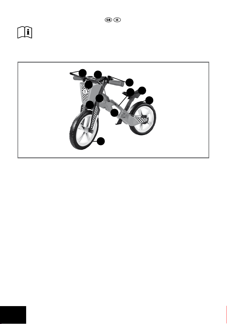
Contents .............................................................................................................................. 6
Technical Specifications .................................................................................................... 6
Designated Use ................................................................................................................. 7
Safety Advice ............................................................................................................... 7 - 8
Danger of Injury .......................................................................................................... 7
Safety Instructions for Use .................................................................................... 7 - 8
Assembly .................................................................................................................... 8 - 13
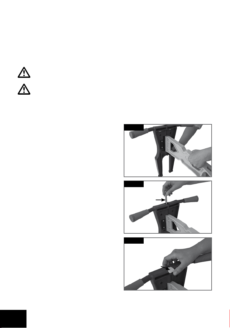
Fork Mounting ............................................................................................................. 8
Mounting Rear Mudguard ......................................................................................... 9
Mounting Saddle ........................................................................................................ 9
Mounting Front Mudguard ......................................................................................... 9
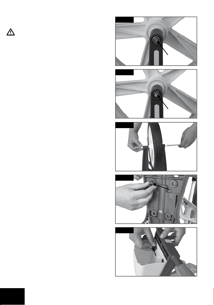
Mounting Front Tire .................................................................................................. 10
Mounting Basket ...................................................................................................... 10
Mounting Bell ............................................................................................................ 11
Mounting Impact Protection ..................................................................................... 11
Mounting Brakes ............................................................................................... 11 - 13
Applying Stickers ...................................................................................................... 13
Settings ..................................................................................................................... 14 - 15
Brakes ........................................................................................................................ 14
Saddle height ........................................................................................................... 14
Steering Angle .......................................................................................................... 15
Care, storage, maintenance .......................................................................................... 16
Disposal ........................................................................................................................... 16
5 Years Warranty ........................................................................................................... 16

6
Read through the instruction manual carefully before use. Make sure you keep
the instructions for future reference!
Contents
(A) 1 x frame (with screw) (L) 1 x nut M8 (page 10)
(B) 1 x fork (M) 1 x basket
(C) 1 x steering head axis (page 8) (N) 4 x rubber washer (page 10)
(D) 1 x cap (page 8) (O) 4 x pin (page 10)
(E) 1 x saddle (P) 1 x impact protection
(F) 1 x rear mudguard (Q) 1 x bell
(G) 2 x screw M5, 16 mm (page 9) (R) 1 x brake lever (with stop screw)
(H) 1 x front mudguard (S) 1 x brake cable (with 2 x Pin)
(I) 1 x screw M3,5, 12 mm (page 9) (T) 1 x manual
(J) 1 x front tire (U) 1 x allen wrench (page 9)
(K) 1 x screw M8, 120 mm (page 10) (V) 2 x sticker set (page 13)
Technical Specifications
Maximum User Weight: 50 kg
Weight: 3.8 kg including Accessories
Saddle Height: 32 cm - 43 cm
Dimensions: 52 x 82 x 44 cm (H x L x W)
A
B
E
F
H
J
M
P
S
Q
R

7
Designated Use
This article has been developed for private use. It is suitable for use as a toy by children
(2 - 5 years, height 85 - 120 cm) with a maximum user weight of 50 kg. This product
does not comply with traffic regulations and may not be used in traffic. Learn about legal
requirements prior to use.
Safety Advice
Danger of Injury!
- Check the article before each use for damage or wear. Check firmness of all
connecting elements and locking parts before each use. Make sure that screws and
nuts that are self-locking are working properly.
- Screws must always be tightened so that children cannot loosen them. Otherwise,
there is the risk that unscrewed could be swallowed or inhaled by children.
Choking hazard!
- Improper alteration or repair of the product may result in hazards! Do not change the
product!
- The article should only be used when in perfect condition! If the article has a defect, it
should not be used until repaired.
- Do not connect the article to other vehicles, sports equipment or other traction devices.
The article is not designed for high speeds.
- Children must always be supervised by an adult when using this article!
- Children must always wear a helmet and sturdy shoes when riding. We also
recommend the use of appropriate protective equipment.
- The article should not be used at night or during periods of poor visibility.
- The article should not be used on sloped ground, near stairs or open waters! Avoid
dangerous areas!
Safety Instructions for Use
- Note that children often cannot assess their own skills and certain dangerous
situations! Due to the need of children to play, unpredictable situations may occur,
which are not the responsibility of the distributor / manufacturer.
- Teach children proper handling of the article and make them aware of possible
dangers!

8
- The child must master braking at all times. Practice braking with the feet and with the
optional brake before using the article.
- Smooth surfaces pose a risk of slipping! Remember that when using this article, there is
always a danger of falling.
Assembly
WARNING!
An adult must always execute the assembly of the article!
WARNING!
Keep children away from the article and packing material during assembly.
Choking hazard due to small parts, which could be swallowed or inhaled, as well as the
risk of suffocation due to plastic bags.
1 Fork Mounting
1a) Insert the frame (A) in the provided
recess on the fork (B).
1b) Insert the steering head screw (C) from
the top in the provided recess and drive
it in until it is flush.
1c) Slide the cover (D).
Fig. 1a
Fig. 1b
Fig. 1c
(C)
(D)

9
2 Mounting Rear Mudguard
Mount the rear mudguard (F) with 2
screws (G).
3 Mounting Saddle
3a) Screw out the barrel adjuster.
3b) Insert the saddle (E) and turn the
adjuster so that is tight.
4 Mounting Front Mudguard
Turn the article over and mount the front
mudguard (H) with the screw (I).
Abb. 2
Fig. 3a
Fig. 3b
Fig. 4
Fig. 2
(G)
(U)
(I)

10
5 Mounting Front Tire
Make sure that the nut (L) is placed
in the square opening (Fig. 5a), the
screw (K) in the round opening
(Fig. 5b).
6 Mounting Basket
6a) Place the 4 rubber rings (N) in the
provided places.
6b) Attach the basket (M) by pressing in the
4 pins (O).
Fig. 5b
Fig. 5c
Fig. 5a
Fig. 6a
Fig. 6b
Place the nut (L), then the screw (K) in the
provided recesses, mount the front tire (J)
and tighten the screw (Fig. 5c).
(L)
(K)
(N)
(O)

11
7 Mounting Bell (optional)
Loosen the screw on the bell (Q), attach the bell on the left
handlebar and then tighten the screw.
9 Mounting Brakes (optional)
WARNING!
If you decide to mount the brake, it must always be adjusted properly
(see seetings, page 14).
9a) Remove the screw from the brake lever
(R), attach the brake lever on the right
handlebar and then tighten the screw.
9b) Hook the brake cable (S) in the lower
intake of the brake arm.
Brake Arm
Fig. 9a
Fig. 7
Fig. 9b
8 Mounting Impact Protection (P)
Pull the Velcro straps around the recesses on the
fork.
Fig. 8

12
9c) Press the brake arm firmly in the
direction of the arrow and hook the
adjustment screw and the lock nut into
the guide.
9d) Run the brake cable (S) along the
frame (A). Press the 2 pins on the brake
cable into the provided recesses
provided on the framework.
9f) Pull the brake lever and hook the brake
cable end (S) into the provided opening
on the brake lever (R).
Locking Nut Adjusting Nut
Brake Cable End
Fig. 9c
Fig. 9d
Fig. 9f
9e) Thread the brake cable (S) through the
tab on the impact protection (P). Fig. 9e
Table of contents
Languages:
Popular Toy manuals by other brands

FUTABA
FUTABA GY470 instruction manual

LEGO
LEGO 41116 manual

Fisher-Price
Fisher-Price ColorMe Flowerz Bouquet Maker P9692 instruction sheet

Little Tikes
Little Tikes LITTLE HANDIWORKER 0920 Assembly instructions

Eduard
Eduard EF-2000 Two-seater exterior Assembly instructions

USA Trains
USA Trains EXTENDED VISION CABOOSE instructions


