Xaoc Devices KATOWICE User manual

KATOWICE
stereo
variable band
isolator
Model of 1978
operator’s manual rev. 1978/1.0

sAluT
Thank you for purchasing this Xaoc Devices
product. Katowice is a stereo variable–band
isolator that allows the user to manipulate
module in a series of upcoming Xaoc Devices
stereo signals.
Katowice splits the stereo input signal into
three bands: low, middle, and high. While
frequency and bandwidth of the mid band,
the low and high bands are automatical-
ly adjusted so that the sum of all three is a
complete signal. All three bands are passed
through high quality VCAs and their stereo
outputs are available separately for further
available.
Katowice may be used as a crossover net-
other band-selective applications, including
multiband compression and stereo enhance-
ment.
InsTAllATIOn
The module requires 10hp worth of free
space in the Eurorack cabinet. The rib-
bon-type power cable must be plugged into
the bus board, paying close attention to po-
larity orientation. The red stripe indicates
the –12V rail and should point in the same
direction on both the bus board and the unit.
The module itself is secured against reversed
power connection, however, reversing the
16-pin header may cause serious damage
to other components of your system because
it will short-circuit the +12V and +5V power
rails.
The module should be fastened by mounting
the supplied screws before powering up. To
better understand the device, we strongly
advise the user to read through the entire
manual before using the module.
mOdulE OVErVIEW
The stereo pair of signal inputs 1is
AC-coupled and accepts all Eurorack signal
levels (up to 20Vpp), however, a conservative
-
ing certain signals may occasionally result
in increased amplitude and cause distortion.
the position of the two knobs: mid freq 2
sets the geometric center of the middle band
(in Hz), and mid width 3sets the width of
this band (in octaves). The corresponding
two jacks 4and 5allow for voltage control
and accept voltages in ±5V range. The ampli-
tude of the middle band is controlled by the
central mid slider 6and the corresponding
CV input above 7that accepts voltages in
the range of ±8V. The left low slider 8and
CV input 9control the amplitude of low fre-
2
module
explained

3
9
2
4
14
13
front panel
overview
interface
3
10
6
11
7
12
5
15
1
8

quencies, and the right high slider 10 and
CV input 11 control the high frequencies. The
middle band signal is available at the stereo
pair of mid outputs 12 . Similarly, the low
band and high band are available at their
stereo pairs of low and high outputs 13
and 14
(post-VCA) is available at the sum pair of
outputs 15 .
fIlTErInG
Splitting the signal into separate frequency
bands is implemented with a set of special
are designed so that with no attenuation, the
sum of all three bands reconstructs the origi-
nal signal without any gaps in the spectrum.
The frequency responses of all three bands
They all offer a 24dB/octave slope beyond
Keep in mind that the mid freq controls
-
ter of the mid band (the middle point in the
when mid freq is set to 2kHz and the mid
width is 2 octaves, the mid band spans from
1kHz to 4kHz (measured at –6dB split point).
When CV inputs are used, manual controls act
as offsets. There is a global limit of the split
below 30Hz and above 20kHz. Also, the mini-
mum width of the mid band is 1 octave.
AmPlITudE COnTrOl
Katowice offers independent amplitude
control for each of its three bands. A slider
in each band allows for attenuation of the
signal down to about –100dB. The response
of this potentiometer is carefully bent to
provide the natural feel of a fader. This at-
tenuation may also be achieved by patching
a negative CV to the corresponding jack. Con-
versely, when the slider is set near the bot-
tom, a positive CV will bring the signal back.
voltage of 8V opens it entirely to unity gain.
In order to prevent hard clipping, each VCA
channel features a soft-saturation circuit
that rounds the peaks of signals approach-
ing 18Vpp.
Katowice ships factory calibrated so that the
trimmer at the back allows for shifting the
gain range (including the limit) up to ±20dB.
4
example frequency response
mid width
20
10
0
-10
-20
-30
-40
-50
-60
10 100 1000 10000
Hz
dB
mid freq

5
block
diagram
Keep in mind that adjusting this will make
panel dB scale relative to what you set.
PhAsE rEsPOnsE
Katowice introduces some phase shift to the
(i.e. the steeper the amplitude response), the
more phase shift is added resulting in a slight
delay.
In Katowice, this delay varies from 0 to 3.5-
4ms and depends on the frequency. There is
-
duced by the AC-coupling capacitors, which
mostly affects very low frequencies.
The phase shift (delay) is generally inaudible
the original signal. However, modulating
modulation of either the mid freq or mid
width parameters) will affect this delay as
well. The side effect is a phenomenon simi-
lar to the Doppler effect wherein you hear a
slight change of the signal's pitch. Similarly
-
block diagram
MID
VCA
VCA
VCA
INPUT
three-way
filter
network
HI
LOW
SUM
MID WIDTH MID FREQ
R
L
band gain CV
inputs

mAIn
fEATurEs
Stereophonic,
3-band, 24dB/oct
crossover module
Voltage
controlled band
Three stereo
VCA blocks
Voltage controlled
attenuation
in each band
TEChnICAl
dETAIls
Eurorack synth
compatible
10hp, skiff
friendly
Current draw:
+100mA / –100mA
Reverse power
protection
EASTERN BLOC TECHNOLOGIES MADE IN THE EUROPEAN UNION
WArrAnTY TErms
XAOC DEVICES WARRANTS THIS PRODUCT TO BE FREE OF DEFECTS IN MATERIALS OR WORKMANSHIP,
AND TO CONFORM WITH THE SPECIFICATIONS AT THE TIME OF SHIPMENT FOR A PERIOD OF ONE YEAR
FROM THE DATE OF PURCHASE. DURING THAT PERIOD ANY MALFUNCTIONING OR DAMAGED UNITS
WILL BE REPAIRED, SERVICED, AND CALIBRATED ON A RETURN-TO-FACTORY BASIS. THIS WARRANTY
DOES NOT COVER ANY PROBLEMS RESULTING FROM DAMAGES DURING SHIPPING, INCORRECT INSTAL-
LATION OR POWER SUPPLY, IMPROPER WORKING ENVIRONMENT, ABUSIVE TREATMENT OR ANY OTHER
OBVIOUS USER-INFLICTED FAULT.
lEGACY suPPOrT
IF SOMETHING WENT WRONG WITH A XAOC PRODUCT AFTER THE WARRANTY PERIOD IS OVER, NO
NEED TO WORRY, AS WE’RE STILL HAPPY TO HELP! THIS APPLIES TO ANY DEVICE, WHEREVER AND
WHENEVER ORIGINALLY ACQUIRED. HOWEVER, IN SPECIFIC CASES, WE RESERVE THE RIGHT TO CHARGE
FOR LABOR, PARTS AND TRANSIT EXPENSES WHERE APPLICABLE.
rETurn POlICY
THE DEVICE INTENDED FOR REPAIR OR REPLACEMENT UNDER WARRANTY NEEDS TO BE SHIPPED IN
THE ORIGINAL PACKAGING ONLY, SO PLEASE KEEP IT JUST IN CASE. ALSO, A FILLED RMA FORM MUST
BE INCLUDED. XAOC DEVICES CAN NOT TAKE ANY RESPONSIBILITY FOR DAMAGES CAUSED DURING
TRANSPORT. PRIOR TO SENDING US ANYTHING, PLEASE CONTACT US AT suPPOrT@XAOCdE-
VICEs.COm. NOTE THAT ANY UNSOLICITED PARCEL WILL BE REJECTED AND RETURNED!
GEnErAl InQuIrIEs
FOR USER FEEDBACK SUGGESTIONS AND DISTRIBUTION TERMS, FEEL FREE TO CONTACT XAOC DEVICES
AT [email protected]. PLEASE VISIT THE XAOCDEVICES.COM FOR INFORMATION ABOUT
THE CURRENT PRODUCT LINE, USER MANUALS, FIRMWARE UPDATES, TUTORIALS, AND MERCHANDISE.
WRITTEN BY M. BARTKOWIAK. EDITED BY Ł. KACPERCzYK. PROOfREADINg AND EDITINg BY B. NOLL.
DESIgNED BY M. ŁOJEK. ALL RIgHTS RESERVED. CONTENT COPYRIgHT © 2020 XAOC DEVICES. COPYINg,
DISTRIBUTION OR ANY COMMERCIAL USE IN ANY WAY IS STRICTLY PROHIBITED AND REQUIRES THE WRIT-
TEN PERMISSION BY XAOC DEVICES. SPECIFICATIONS ARE SUBJECT TO CHANGE WITHOUT PRIOR NOTICE.
This manual suits for next models
1
Table of contents
Other Xaoc Devices Synthesizer manuals

Xaoc Devices
Xaoc Devices KARL MARX STADT User manual

Xaoc Devices
Xaoc Devices ROSTOCK User manual

Xaoc Devices
Xaoc Devices WARNA 1983 VOLTAGE DISTRIBUTOR II User manual

Xaoc Devices
Xaoc Devices BATUMI User manual

Xaoc Devices
Xaoc Devices BELGRAD User manual

Xaoc Devices
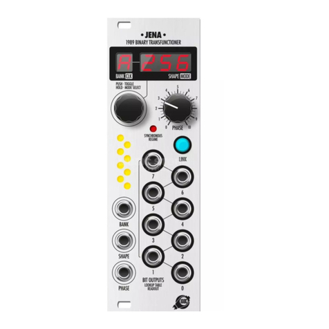
Xaoc Devices JENA User manual

Xaoc Devices
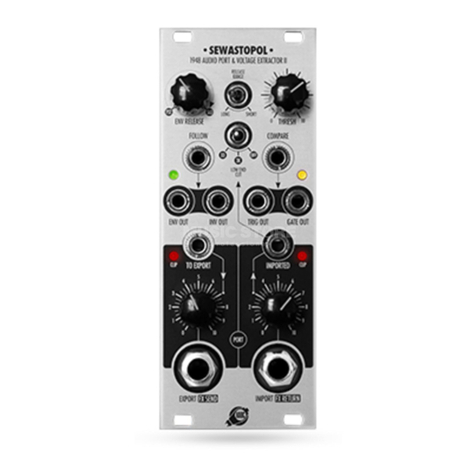
Xaoc Devices SEWASTOPOL User manual

Xaoc Devices
Xaoc Devices KARL MARX STADT User manual

Xaoc Devices
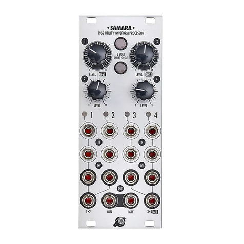
Xaoc Devices SAMARA User manual

Xaoc Devices
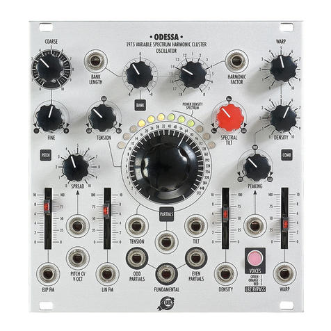
Xaoc Devices ODESSA User manual