Xaoc Devices ROSTOCK User manual

ROSTOCK
THE LEIBNIZ BINARY SUBSYSTEM
binary data
pipeline
Model of 1989
operator’s manual rev. 1989/X6/1.0

SALUT
Thank you for purchasing this Xaoc Devices
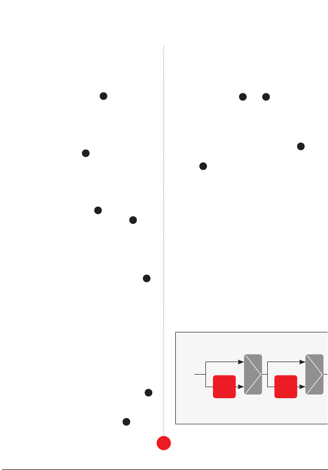
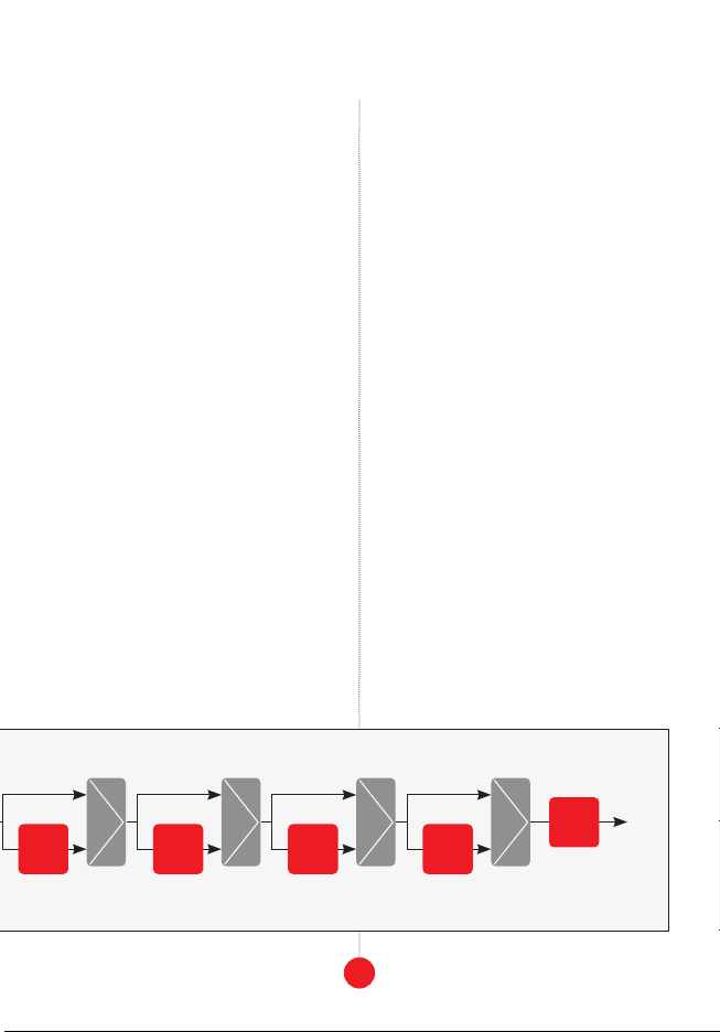
product. Rostock is a data pipeline,
very short digital delay. Its length is variable
from 1 to 64 stages (with optional looping and
scrambling). Rostock is a component of the
modules that operate on 8-bit data. It works by
processing data in the Leibniz bus and must be
connected to other Leibniz modules using data
ribbon cables at the back. Rostock may process
data sequences representing rhythms, control
voltages, audio-rate signals, and even video
signals because the bits can change at extreme
rates (up to 2MHz). In addition, its memory
may be digitally looped. Delaying and looping
is a fundamental building block for sequence
automation, pattern and chaos generation,
and various cybernetic modular patches. Thus,
Rostock is a multi-purpose open-ended device
that invites creative thinking.
To better understand the device and avoid
common pitfalls, we strongly advise the user
to read through the entire manual before use.
INSTALLATION
The module requires 8hp worth of free space
in the Eurorack cabinet. Always turn the pow-
er off before plugging the module into the
bus board using the supplied 16-pin to 16-pin
ribbon cable, paying close attention to power
cable pinout and orientation. The red stripe
indicates the negative rail and should match
the dot or –12V mark on the bus board as
well as the unit. Rostock is internally secured
may cause serious
damage to other components of your system
because it will short-circuit the +12V and +5V
power lines. Always pay close attention to the
proper orientation of your ribbon cable on
both sides!
Besides power, you need to connect Rostock to
other components of your Leibniz Subsystem.
We advise you to plan ahead as to how you
wish to incorporate Rostock into your modular
setup. The module ships with one 10-pin ribbon
data cable, so you will need to use the addi-
tional 10-pin cables included with your other
Leibniz modules to complete the connection.
First, connect the 10-pin unshrouded header
labeled out to the in header of your next Leib-
niz-compatible module (e.g., Drezno, Poczdam,
Lipsk, Jena, Erfurt, Odessa, etc.). Then connect
the out header of the module that will provide
input data to Rostock (e.g., Poczdam, Drezno,
Erfurt, Ostankino, etc.) to the 10-pin unshroud-
ed header labeled in. Please observe the marks
of pin #1 (red stripe) on all connected modules.
warning: do not plug a power cable
into the leibniz headers; this will dam-
age your unit and may also jeopardize
other leibniz modules connected to it!
The module should be fastened by mounting
the supplied screws before powering up.
MODULE OVERVIEW
Contrary to many other modules in the Leib-
niz series, Rostock does not offer data input or
data output jacks. Hence it relies entirely on
the data connections at the back of the mod-
ule. It features a bank of eight clock inputs 1,
2
module
explained

3
front panel
overview
5
8
6
10
3
2
9
12
11
7
4
1
the interface

4
which allows you to replace the original Leib-
niz clock arriving with the source data (inde-
pendently for each bit!). Therefore, the timing
of each individual bit line may be different.
An additional clock input 2enables you to
substitute the output data clock with any oth-
er signal. This clock does not affect the pipe-
the Leibniz data chain.
The bank of 8 LEDs 3displays the status of
each bit output of the delay line, where the
(bit 7), and the lowest one represents the least
0).
The 2-digit LED display 4at the top of the
front panel and the endless encoder 5offer
two functions. By default, the display shows
the length of the delay line (the number of
stages of the shift register) while the encod-
er changes this value in the range of 1-64. In
addition, this length may be modulated by an
external CV plugged into the input below 6
,
which accepts bipolar voltages in the range of
-10V to 10V.
Pressing the encoder knob switches the dis-
play and encoder function to adjust the mod-
ulation depth from 0 to 99%. This secondary
function is indicated by an additional dot on
the display. Pressing the encoder again re-
turns to the default operation.
There are two illuminated buttons below the
display. The right button labeled loop 7
switches between new data being written 1:1
to the pipeline or closing the loop around it.
The left button labeled scramble 8toggles
between a 100% loop (input data is ignored
and the content losslessly recirculates) and an
XOR-style loop (input data is combined with
the output data and written back to the input).
Two gate input jacks 9and 10 below each
of these two buttons allow for remote looping
control. Note that the scramble function has
no effect when looping is off. The entire con-
tent of the pipeline’s memory may be cleared
by pressing the small button labeled clear 11
or by a trigger or gate signal sent into the jack
above it 12 .
THE PRINCIPLE OF OPERATION
Rostock operates similarly to a BBD delay or
an ASR (analog shift register), except that
it is digital. It consists of a chain of memo-
ry cells that pass bits from one to another at
each clock cycle.
There are eight such chains inside Rostock
operating in parallel: one for each of the bits
in the 8-bit Leibniz data. The length of these
chains may be set in the range of 1 to 64 stag-
es via the encoder and screen as well as exter-
nal CV. For example, when the length is set at
48, the input data passes through 48 memory
select
32
stages
select
16
stages

cells and is delivered to the output after 48
cycles of the clock. In other words, the data is
digitally (and losslessly) delayed.
The physical delay is a product of the clock pe-
riod and the length of the pipeline. For exam-
ple, with a 2MHz clock, it can vary from 0.5us to
a 5kHz clock it can vary from 0.2ms to 12.8ms
clock it will be 100ms to 6.4s (rhythm and LFO
range).
Varying the length changes the number of
memory cells used. Changing the length while
a signal is being processed yields some idio-
syncratic digital distortion. To understand this
distortion, you need to understand the internal
The delay length selects a combination of
8 stages, 4 stages, 2 stages, and 1 stage, plus
-
lay is never 0. While the input data always
passes through all blocks, some blocks are
omitted in the current pipeline by insert-
ing the input data directly into some later
blocks. For example, when the length is set
and the remaining blocks are skipped, ex-
is skipped, and the 16, 8, 4, 2, and 1-stage
blocks are used. These, combined with the
Note that such switching (only by 1) yields
sometimes, an interesting glitch.
LOOPING & SCRAMBLING
When the loop button is unlit, the device op-
erates as a straightforward delay: new data
from the Leibniz in is written to the shift reg-
ister at each rising edge of the clock, it is de-
layed by the number of clock pulses set with
the encoder and shown on the display, and it
is passed to the Leibniz out.
With the loop function activated (by press-
ing the button or plugging a 5V gate into the
loop control input jack), the output data
from the pipeline is fed back to the input.
This function allows you to catch a sequence
of data representing, e.g., one cycle of a
waveform or a drum pattern and repeat it as
long as needed.
5
the structure of the pipeline in rostock
select
8
stages
select
4
stages
select
2
stages
select
1
stage
1
stage

note: The length of the loop will equal the
length of the pipeline. If you change the length,
it will cause glitches, as discussed in the previ-
ous section. Shortening the loop while playing
back the data will overwrite the unused mem-
ory cells with the shortened loop. If the length
is increased afterward, the pipeline will still
contain the shortened loop only.
The scramble button (together with the sig-
nal sent to the control input jack) changes the
looping behavior. When activated, the pipeline
is fed with both the input and output bits, com-
table for this function). For example, if the in-
put bit is a constant 1, the stream of data bits
from the output will be inverted and written
back to the input, thus generating a cyclic pat-
tern every two lengths of the pipeline. Feeding
the input with more or less varying data and
operating the scramble function allows for
creating cyclic binary patterns of various
complexity, similar to 8 channels of a bina-
ry Turing machine, or a 256-valued discrete
state machine, or anything in between, de-
pending on how you patch them.
You can reset the loop’s content at any point
by pressing the small clear button or plug-
ging a gate signal into the control input jack
above it.
CLOCKS
In general, the physical delay offered by Ros-
tock may be changed continuously within an
extreme range by varying the source clock.
Note that this delay is inversely proportional
to the clock frequency: you can increase the
delay 1000 times by slowing the clock down
by 1000 times. This, however, comes at the
cost of temporal resolution because data will
be sampled 1000 times slower.
By default, Rostock uses the source clock that
arrives together with the input data via the
Leibniz interface to drive its internal shift
registers. Since each data bit is processed by
a separate chip, it is possible to change the
timing of each bit’s pipeline by replacing the
default clock using the front panel jacks. For
data representing audio, this will naturally
destroy the signal integrity as individual bits
will be delayed differently. However, when you
use individual Leibniz bits as channels of a
trigger sequence, this timing behavior is ideal
for creating rhythmic changes.
note: There is no limit to how slow the clock
can be, and it doesn’t even have to be a regu-
lar pulse train. You can plug a stream of ran-
dom gates or bits of the binary data there.
The Leibniz hardware makes no distinction
between clocks and binary gate signals.
PATCH IDEAS
• Using Drezno with Rostock allows for ex-
perimenting with short delays on analog CV
6
input a input b output
000
011
101
110
the truth table of the ‘xor’ function

7
patch
ideas
and audio signals: connect the Leibniz out
of Drezno to the in header of Rostock and the
out header of Rostock back to the Leibniz in
header of Drezno. Replace the MHz internal
ADC clock with a slower oscillator. Alterna-
tively, you can create an analog feedback
loop using a simple mixer. To do that, con-
nect your original signal to one mixer input.
Next, connect the output of the mixer to the
adc input of Drezno. Finally, connect the
dac output of Drezno to another input of
the mixer and mult this dac output to use
tip: Carefully set the gain and offset sliders
in Drezno, especially with deep feedback, as it
will tend to accumulate the DC offset and eat
your headroom. You can prevent this by invert-
ing or AC-coupling the signal before patching
it to the feedback input of your mixer.
• Use Rostock as a delay loop for Jena to
achieve a multi-attractor chaotic oscillator
patch. Connect the out header of Rostock
to the in header in Jena and the out head-
er of Jena to the in header of Rostock. If you
need an analog output, you can use a split-
ter Leibniz cable (sold separately or DIY) to
connect the same out of Jena to Drezno’s lbz
in header. Alternatively, you can connect the
front panel outs of Jena to the front panel in-
puts of Drezno.
tip:
especially if you start with a wave that maps
0 to 0, or is generally monotonic. Use Jena’s
phase knob or the phase CV input to kick it
out of this. Also, experiment with different
clock frequencies plugged into the outg.
clock in.
• Connect Lipsk’s out header to one of the in
headers of Poczdam, the out2 of Poczdam
to the in header of Rostock, and the out of
Rostock back to the in of Lipsk. Activate link.
Use your own clock to drive the sequence
through the outg. clock in. This patch is a
programmable trigger/gate sequencer with
8 channels and up to 64 steps. Use Lipsk’s
buttons to change the state of individual
lines. Poczdam’s front panel outputs are your
trigger outs, and the sequence length is set
in Rostock. At any time you can loop Rostock
locally to ignore the state of Lipsk or activate
scramble to generate random patterns.
• Connecting Rostock in a loop with Poczdam
gives access to all the bit outputs and inputs
to mangle. For example, you can patch an
8x64=512 stage one-bit delay by connecting
all channels in series: use seven patch cables
to connect Rostock’s out 7with in 6, out 6
with in 5out 1 to
in 0. Your single bit input is in 7, and out 0
is the output of the long chain. Using split-
ter patch cables and different clocks for the
individual bits, you may patch a multi-tap
trigger delay to drive a sequence of events in
your modular.
CONNECTIVITY
Rostock connects to all modules compatible
with the Leibniz Binary Subsystem: Drezno,
Lipsk, Gera, Jena, Erfurt, Poczdam, Ostankino
II, and Odessa.
ACCESSORY
Our Coal Mine black panels are available for
all Xaoc Devices modules. Sold separately.
Ask your favorite retailer. •

MAIN
FEATURES
Leibniz Binary
Subsystem com-
ponent
Shift register /
delay memory of
up to 64 stages
Voltage controlled
length
Looping and
scrambling
Optional individ-
ual clock input to
each bit line
TECHNICAL
DETAILS
Eurorack synth
compatible
8hp, skiff
friendly
Current draw:
+70mA/-40mA
Reverse power
protection
NOT protected
against plugging
power to Leibniz
headers!
EASTERN BLOC TECHNOLOGIES MADE IN THE EUROPEAN UNION
ALL RIGHTS RESERVED. CONTENT COPYRIGHT ©2023 XAOC DEVICES. COPYING, DISTRIBUTION, OR COM-
MERCIAL USE IN ANY WAY IS STRICTLY PROHIBITED AND REQUIRES WRITTEN PERMISSION FROM XAOC
DEVICES. SPECIFICATIONS ARE SUBJECT TO CHANGE WITHOUT PRIOR NOTICE. EDITING BY BRYAN NOLL.
WARRANTY TERMS
XAOC DEVICES WARRANTS THIS PRODUCT TO BE FREE OF DEFECTS IN MATERIALS OR WORKMANSHIP
AND TO CONFORM WITH THE SPECIFICATIONS AT THE TIME OF SHIPMENT FOR ONE YEAR FROM THE
DATE OF PURCHASE. DURING THAT PERIOD, ANY MALFUNCTIONING OR DAMAGED UNITS WILL BE
REPAIRED, SERVICED, AND CALIBRATED ON A RETURN-TO-FACTORY BASIS. THIS WARRANTY DOES NOT
COVER ANY PROBLEMS RESULTING FROM DAMAGES DURING SHIPPING, INCORRECT INSTALLATION OR
POWER SUPPLY, IMPROPER WORKING ENVIRONMENT, ABUSIVE TREATMENT, OR ANY OTHER OBVIOUS
USER-INFLICTED FAULT.
LEGACY SUPPORT
IF SOMETHING GOES WRONG WITH A XAOC PRODUCT AFTER THE WARRANTY PERIOD IS OVER, THERE IS
NO NEED TO WORRY, AS WE’RE STILL HAPPY TO HELP! THIS APPLIES TO ANY DEVICE, WHEREVER AND
WHENEVER ORIGINALLY ACQUIRED. HOWEVER, IN SPECIFIC CASES, WE RESERVE THE RIGHT TO CHARGE
FOR LABOR, PARTS, AND TRANSIT EXPENSES WHERE APPLICABLE.
RETURN POLICY
THE DEVICE INTENDED FOR REPAIR OR REPLACEMENT UNDER WARRANTY NEEDS TO BE SHIPPED IN
THE ORIGINAL PACKAGING ONLY AND MUST INCLUDE A COMPLETED RMA FORM. XAOC DEVICES CAN
NOT TAKE ANY RESPONSIBILITY FOR DAMAGES CAUSED DURING TRANSPORT. SO BEFORE SENDING
UNSOLICITED PARCEL WILL BE REJECTED AND RETURNED!
GENERAL INQUIRIES
FOR USER FEEDBACK SUGGESTIONS, DISTRIBUTION TERMS, AND JOB POSITIONS, FEEL FREE TO CON-
FORMATION ABOUT THE CURRENT PRODUCT LINE, USER MANUALS, FIRMWARE UPDATES, TUTORIALS,
AND MERCHANDISE.
Table of contents
Other Xaoc Devices Synthesizer manuals

Xaoc Devices
Xaoc Devices HEL User manual

Xaoc Devices
Xaoc Devices BATUMI User manual

Xaoc Devices
Xaoc Devices ODESSA User manual

Xaoc Devices
Xaoc Devices KARL MARX STADT User manual

Xaoc Devices
Xaoc Devices KARL MARX STADT User manual

Xaoc Devices
Xaoc Devices JENA User manual

Xaoc Devices
Xaoc Devices BELGRAD User manual

Xaoc Devices
Xaoc Devices SEWASTOPOL User manual

Xaoc Devices
Xaoc Devices SAMARA User manual

Xaoc Devices
Xaoc Devices KATOWICE User manual