Xaoc Devices SAMARA User manual

SAMARA
utility
waveform
processor
Model of 1962
operator’s manual rev. 1962/1.0

SAlut
Thank you for purchasing this Xaoc Devices prod-
uct. Samara is a "Swiss Army Knife" type of mod-
ule, intended to serve the most common voltage
and audio signal processing purposes such as at-
tenuation, offsetting, mixing, inverting, and even
basic waveshaping. We have designed it to com-
plement the ever-popular Batumi module but it
will happily serve all these functions on its own.
inStAllAtiOn
The module requires 10hp worth of free space
in the eurorack cabinet. The ribbon type power
cable must be plugged into the bus board, pay-
ing close attention to polarity orientation. The
red stripe indicates the negative 12V rail and is
supposed to point in the same direction on both
the bus board and the unit. The module itself is
secured against reversed power connection,
however reversing the 16-pin header may cause
serious damage to other components of your
system, because it will short-circuit the +12V
and +5V power rails. The module should be fas-
tened by mounting the supplied screws before
powering up. To better understand the device,
we strongly advise the user to read through the
entire manual before using the module.
BASic feAtuReS
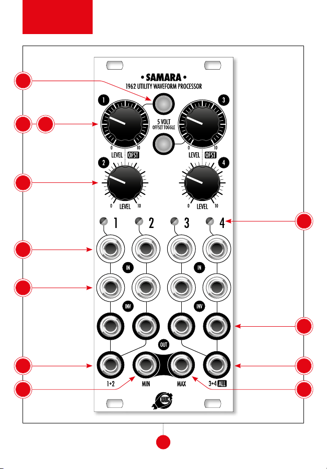
Samara features four channels—each with two
inputs and an attenuator, additional switchable
offset generators, four voltage level and polarity
indicators, two adders with switchable scale,
and a precision four-channel processor that se-
lects minimum and maximum voltage. See the
AttenuAtiOn, inVeRtinG & OffSet
are four identical channels. Each channel features
a regular in input 1as well as an inverting inv
input 2. The difference between these inputs is
adjusted by an active attenuator. Each unused in-
put is normalized to 0V, hence this arrangement
allows for two independent channels of normal
attenuation, or inverting attenuation, or comput-
ing a difference between two voltages or signals.
Additionally, two sources of a stable +5V
voltage are switchable in channels 1and 3,
activated by pressing the corresponding illu-
minated button 3. This offset is added to the
inputs before attenuation. Thus, if nothing is
patched to the inputs of channels 1and/or
3, they can be used as a source of constant
voltage, from 0 to 5V. The resulting signal or
voltage, after being manually attenuated by
the level/ofst knob 5, is available on the
corresponding out outputs 6.
To achieve independent control over scale and
offset two channels must be utilized: one for
offset (with the 5V offset toggle engaged
and nothing patched into the inputs) and an-
other one for scaling.
A bi-color LED 7indicates the value and polar-
ity of the voltage through corresponding bright-
ness and color. For audio signals, fast blinking of
red and green yields a yellow-orange mixture
with intensity corresponding to signal level.
Note that you may use the individual outputs
to re-direct the processed channels to other
channels. For example, an attenuated signal or
2
module
explained

3
10 11
3
4 5
4
1
6
7
2
9 8
front panel
overview

CV from channel 2 can be patched to channel 3
with offset turned on. Changing the attenuator
in channel 2will not affect the offset. Also, an
offset from channel 1 or 3 can be patched to an
inverting input of channel 2or 4, thus a nega-
tive offset can be easily achieved.
MiXinG
A cascaded arrangement of summers allows for
the mixture of all channels with the ability to
break the sum into two sub-mixes. To mix four
signals, feed them into inputs 1and adjust the
level knobs 4. The resulting signal is available
at the all socket 8(make sure that nothing is
plugged into 1+2 output socket 9). Additional-
ly, you can use the inverting inputs 2to mix up
to eight signals.
To use Samara as two independent 2:1 mixers,
use both 1+2 9and 3+4 8output. Patching a
cable to 1+2 output breaks the internal connec-
tion, and these two channels are no longer mixed
with channels 3and 4. Again, using the inverting
inputs allows for two four-component mixes.
Since mixing multiple hot signals with little at-
tenuation usually yields overdrive (especially
at the ALL output 8), a soft-clipping solution
is offered. It can be turned off by removing the
jumper at the batck of the PCB. Additionally,
optional -6dB (2:1) attenuation is available in-
dependently for 1+2 and 3+4 summers by using
two jumpers on the back of the module. Switch-
ing just one jumper does not affect the ampli-
tude of the second summer. Note that the all
mix will have unequal proportions in such case.
Also, note that the jumpers do not affect the op-
eration of the min and max outputs (see below).
MiniMuM & MAXiMuM OutS
In addition to linear mixing, Samara features a
precision min/max computing circuit that out-
puts the current minimum voltage of all the (at-
tenuated) channels at the min 10 output, as well
as the maximum voltage at the max 11 output.
This circuit is intended for processing control
voltages, such as LFO waveforms, envelopes,
etc. However, it does provide interesting re-
4
dB
Hz
dB
Hz
2
0
-2
2
0
-2
MIN
MAX
MIN
MAX

waveshaper. For example, by processing just a
single waveform in one channel, it is compared
to 0V from the remaining channels, hence a
max output and the negative halves are avail-
able at the min output. Also, by patching the
max or min output back to any of the inputs
allows one to independently scale the upper or
the lower half of the waveform by using the cor-
waveform can be produced by patching back
the min output to the inverting input of anoth-
er channel. Furthermore, by feeding a constant
CV to all remaining channels, the splicing point
of the waveform can be altered. Be aware that
channels without an input signal (or channels
attenuated to 0) will be treated as 0V, which af-
fects the operation of min and max. If you don’t
want that, simply feed unused channels with a
5
block
diagram
inputs
inputs inputs
inputs
ind. output
ind. output ind. output
ind. output
sub mix / all mix
sub mix
fiXed OffSet
AnAlYSiS
AttenuAtiOn AttenuAtiOn
1 3
2 4

MAin
feAtuReS
Four attenuation
channels
Two offset
channels
Four inverters
One four-channel
mixer
Two double-
channel mixers
Mixing of up to
eight signals
when using
inverted inputs
Minimum/
maximum
selection circuit
Basic
waveshaping
technicAl
detAilS
Eurorack synth
compatible
10hp, skiff
friendly
Current draw:
+25mA/-20mA
Reverse power
protection
EASTERN BLOC TECHNOLOGIES MADE IN THE EUROPEAN UNION
WARRAntY teRMS
XAOC DEVICES WARRANTS THIS PRODUCT TO BE FREE OF DEFECTS IN MATERIALS OR WORKMANSHIP,
AND TO CONFORM WITH THE SPECIFICATIONS AT THE TIME OF SHIPMENT FOR A PERIOD OF ONE YEAR
FROM THE DATE OF PURCHASE. DURING THAT PERIOD ANY MALFUNCTIONING OR DAMAGED UNITS
WILL BE REPAIRED, SERVICED, AND CALIBRATED ON A RETURN-TO-FACTORY BASIS. THIS WARRANTY
DOES NOT COVER ANY PROBLEMS RESULTING FROM DAMAGES DURING SHIPPING, INCORRECT INSTAL-
LATION OR POWER SUPPLY, IMPROPER WORKING ENVIRONMENT, ABUSIVE TREATMENT OR ANY OTHER
OBVIOUS USER-INFLICTED FAULT.
leGAcY SuPPORt
IF SOMETHING WENT WRONG WITH A XAOC PRODUCT AFTER THE WARRANTY PERIOD IS OVER, NO
NEED TO WORRY, AS WE’RE STILL HAPPY TO HELP! THIS APPLIES TO ANY DEVICE, WHEREVER AND
WHENEVER ORIGINALLY ACQUIRED. HOWEVER, IN SPECIFIC CASES, WE RESERVE THE RIGHT TO CHARGE
FOR LABOR, PARTS AND TRANSIT EXPENSES WHERE APPLICABLE.
RetuRn POlicY
THE DEVICE INTENDED FOR REPAIR OR REPLACEMENT UNDER WARRANTY NEEDS TO BE SHIPPED IN
THE ORIGINAL PACKAGING ONLY, SO PLEASE KEEP IT JUST IN CASE. XAOC DEVICES CAN NOT TAKE
ANY RESPONSIBILITY FOR DAMAGES CAUSED DURING TRANSPORT. PRIOR TO SENDING US ANYTHING,
CEL WILL BE REJECTED AND RETURNED!
GeneRAl inQuiRieS
FOR USER FEEDBACK SUGGESTIONS, DISTRIBUTION TERMS, JOB POSITIONS FEEL FREE TO CONTACT
FORMATION ABOUT THE CURRENT PRODUCT LINE, USER MANUALS, FIRMWARE UPDATES, TUTORIALS,
AND MERCHANDISE.
ALL RIGHTS RESERVED. CONTENT COPYRIGHT © 2016 XAOC DEVICES. COPYING, DISTRIBUTION OR
ANY COMMERCIAL USE IN ANY WAY IS STRICTLY PROHIBITED AND REQUIRES THE WRITTEN PER-
MISSION BY XAOC DEVICES. SPECIFICATIONS ARE SUBJECT TO CHANGE WITHOUT PRIOR NOTICE.
Table of contents
Other Xaoc Devices Synthesizer manuals

Xaoc Devices
Xaoc Devices HEL User manual

Xaoc Devices
Xaoc Devices ROSTOCK User manual

Xaoc Devices
Xaoc Devices KATOWICE User manual

Xaoc Devices
Xaoc Devices KARL MARX STADT User manual

Xaoc Devices
Xaoc Devices JENA User manual

Xaoc Devices
Xaoc Devices BATUMI User manual

Xaoc Devices
Xaoc Devices SEWASTOPOL User manual

Xaoc Devices
Xaoc Devices KARL MARX STADT User manual

Xaoc Devices
Xaoc Devices WARNA 1983 VOLTAGE DISTRIBUTOR II User manual

Xaoc Devices
Xaoc Devices ODESSA User manual