Xirrus XR-1000 Series User manual

XR Series
Wireless
Arrays
XR-1000 Series
January 30, 2013

is a registered trademark of Xirrus, Inc. All other trademarks and brand names are marks of their
respective holders.
Please see Legal Notices, Warnings, Compliance tatements, and Warranty and License Agreements in the Wireless
Array User’s Guide.
All rights reserved. This document may not be reproduced or disclosed in whole or in part by any means without
the written consent of Xirrus, Inc.
Part Number: 812-0085-002B January 30, 2013

1
Quick Installation Guide
For XR-1000 Models
This Guide covers the steps required to install the
Xirrus XR-1000 eries Wireless Array on a T-bar ceiling
grid and execute the initial power up of the Array. If
installing the Array with a different type of Xirrus
mounting, refer to the specific Quick Installation Guide
for that mounting kit.
For additional information, see the Wireless Array User’s Guide.
This document is intended only for XR-1000 Series Arrays. It does not include the XR-1000H
Series. For other XR models, please see the appropriate uick Installation Guide.
1
You Need the Following Items
Accessory Kit (included in each Wireless Array carton), containing four ceiling mount clip
sets.
Workstation with a Web browser to configure the Wireless Array.
Flat screwdriver and 7/16” nut driver for attaching the T-bar clips to the ceiling grid.
Knife for cutting an access hole in the ceiling tile.
Copper Ethernet connection(s) to your wired network.
Power—XR-1000 Arrays are powered via Power over Gigabit Ethernet (PoGE) using an
Ethernet Cat 5e or Cat 6 cable that also carries data traffic. You must provide a network
connection and Ethernet cable run from an injector port for the Array Gigabit port. The
PoGE module requires an AC outlet. A splitter is incorporated in the Array. Use only Xirrus-
supplied PoGE injectors. ee the PoGE Installation Guide for more information.
XR-1000 Arrays are powered by one injector port rated at 33W or higher.
The Array must be connected to PoGE networks without routing cabling to the outside plant—
this ensures that cabling is not exposed to lightning strikes or possible crossover from high
voltage lines.

2
2
Choose a Suitable Location
The best location is ceiling-mounted within an open plan environment. Choose a location
that is central to your users. Refer to the Wireless Array User’s Guide. For optimal placement,
we recommend that a predictive survey be performed by a qualified Xirrus partner.
Keep the unit away from electrical devices or appliances that generate RF noise—at least 3
to 6 feet (1 to 2 meters).
Maintain a distance of at least 50 feet between additional Wireless Arrays.
3
Mark the Placement of the T-Bar Clips
Refer to Figure 1. You have been provided a small mounting plate. Drawings for the plate with
dimensions are on page 12.
Suggested location of
cable feed opening
Array may be secured to
this attachment with zip tie
Four short arrows show mounting holes
Figure 1. Marking the Location of the T-Bar Clips for the mall Mounting Plate
Use the Array mounting plate to mark the placement of the four T-bar clips on the metal
ceiling support grid. Note the four mounting holes indicated in Figure 1. Use them to attach
the plate to the T-bar. Position the plate to line up the holes with the ceiling grid. Mark four
locations on the grid.
On the ceiling tile, mark where to cut an opening for
the cable.
For the small mounting plate, if you will be securing
the Array to the mounting plate with a zip tie, slide
the attachment open as needed for the size of the
Array. Make sure that a hole in the attachment lines
up with the mounting hole so that the mounting hole
is not blocked. (Figure 2)
Figure 2. lide attachment open

3
4
Secure the T-Bar Clips to the Ceiling Support Grid
Refer to Figure 3.
Twist the four T-bar clips onto the metal ceiling support grid at the marked locations and
tighten the screw posts to 10-12 lbf.ft (1.38-1.66 kgf.m). Do not overtighten the screw posts.
Cut an access hole for the cable in the ceiling tile.
You MUST use the mounting studs that are furnished with the ceiling mounting bracket
accessory kit for the XR Array. Do NOT reuse the longer ones furnished with XS or XN
Arrays—they will interfere with and scratch the XR Array.
Figure 3. ecuring the T-Bar Clips to the Grid

4
5
Install the Mounting Plate
Refer to Figure 4.
Align the Array’s mounting plate and secure it to the four T-bar clips using the nuts
provided. Tighten the nuts to 10-12 lbf.ft (1.38-1.66 kgf.m), but do not overtighten.
Figure 4. Installing the Mounting Plate
If you wish to secure the Array to the mounting plate, slide open the attachment and feed a
zip tie through it. You will secure it to the Array later.

5
6
Connect the Cable
Refer to Figure 5 and Figure 6.
All XR Array models have integrated splitters, so external splitters are not used. ee the
PoGE Installation Guide for details on the Xirrus-supplied injector modules and Array
compatibility.
Power: These Arrays are only powered through the Gigabit POE port. Only Xirrus-supplied
power injectors may be used.
Data: Data is supplied to the Gigabit port via the same cable that powers the Array.
Feed the Cat 5e or Cat 6 cable through the access hole in the ceiling tile.
Connect the Ethernet cable carrying data and power from the PoGE injector to the Array’s
Gigabit POE port as indicated in Figure 5.
Gigabit POE (gig1)
Figure 5. Network Interface Port—XR-1000 eries

6
7
Attach the Wireless Array to the Mounting Plate
Refer to Figure 6.
Align the keyed slot in the center of the Array with the key post on the mounting plate.
Key Post
Lug
Alignment Hole
Figure 6. Attaching the Array to the Mounting Plate
Turn the Wireless Array to the right to lock the unit into place—similar to the assembly of a
smoke detector.
If you are using a zip tie, feed it through the loop on the Array and secure it.

7
8
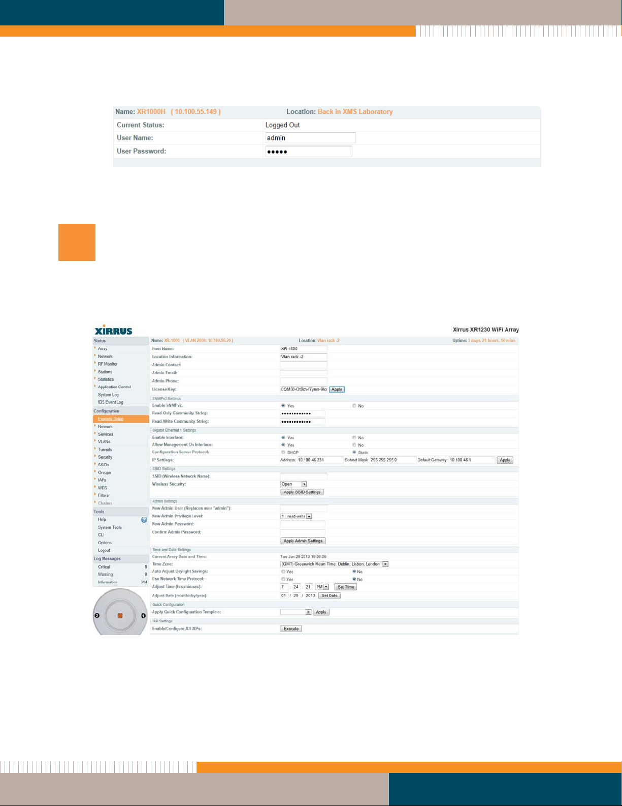
Log In to the Wireless Array
Refer to Figure 7.
NOTE: If you are a Xirrus Cloud customer, your Arrays are completely managed by XMS
Cloud, and you may skip all of the remaining steps (8 to 10). In fact, you will not be able to
access CLI or the Web Management Interface under normal operating circumstances.
If you are a Xirrus Cloud customer, installation is complete at this point. Wait five
minutes, then log on to XMS Cloud to view or manage this Array. In the event that your
connection to the Cloud has been interrupted for an extended period of time, you may
contact Xirrus technical support for help with local access to the Array.
Establish a network connection to the Array using a web browser. In the URL field, enter the
IP address assigned by your DHCP server. If you are using DHCP and DN , use the Array's
default host name, which is its serial number (for example, XR0823090CACD).
Be aware of the following:
By default, the Array tries to obtain an IP address via DHCP. If it cannot do so, the
factory default is a static IP address of 10.0.2.1 with a mask of 255.255.255.0 on its
Gigabit POE port.
Take care to ensure that your network is not using the 10.0.2.1 IP address prior to
connecting the Array to the network.
To connect to the Array in this case, you must set your laptop to be in the same
subnet as the Array: set your laptop’s IP address to be in the 10.0.2.xx subnet, and set
its subnet mask to 255.255.255.0. If this subnet is already in use on your network, you
may connect your laptop directly to the Array by connecting the laptop to the power
injector’s IN port temporarily (this port may be called the WITCH port or the DATA
port on your injector).
If the assigned IP address is unknown, you may obtain the Xirrus Xircon utility from
Customer upport to communicate with any XR-1000 on the local network. Note that
the XR-1000 eries does not have a console port, so Xircon has been specifically
designed to substitute for the use of a console port. Please see “ ecuring Low Level
Access to the Array” on page 10 for more information about Xircon. For the best
results, you may wish to connect your laptop directly to the Array as described in the
previous paragraph.
If your browser reports a ecurity exception, go ahead and accept it and continue on to the
Array’s Web Management Interface (WMI).

8
At the login prompt, enter the default user name / password (the default is admin for both).
Figure 7. Login Prompt
You are now logged in to the Wireless Array.
9
Configure the Wireless Array
Click on Express Setup. Refer to Figure 8.
Figure 8. Express etup Window
When a newly deployed Array boots up, it automatically contacts Xirrus with its serial
number and MAC address and obtains its license key. Any unlicensed Array will auto-

9
license in this way after it boots up, if it has Internet connectivity. You should see the key in
the License Key field.
In the Admin Settings section, change both the default admin username and password to
improve Array security. Enter New Admin User and New Admin Password, then Confirm
Admin Password. Leave New Admin Privilege Level at read write. Click Apply Admin
Settings when done.
Be sure to record the new account name and password, because the default admin user will
be deleted!
Quick Configuration (near the bottom of the page): This offers predefined configuration
options such as Classroom and High-Density that capture best practices from years of field
experience. If one of the options in the drop-down list is appropriate to your deployment,
select it and click Apply. For example, the High-Density option uses best practices to
configure the Array for high density settings such as lecture halls, convention centers,
stadiums, etc.
If you make changes to the SSID Settings section, click the associated Apply button to
apply your changes.
Click Save Changes to Flash on the upper right to save your settings.
Click Execute at the bottom of the page to set up/enable all IAPs (radios) automatically.
For improved security, you must also take the additional steps described in “Securing Low
Level Access to the Array” on page 10.
With a basic configuration established the Wireless Array is now functional. Refer to the
Wireless Array User’s Guide for additional configuration information. Look for the section
titled Perfor ing the Express Setup Procedure near the end of the Installing the Wireless Array
chapter of the Guide for more details on Express Setup settings. The chapter titled
Configuring the Wireless Array discusses all of the settings available for the Array.

10
10
Securing Low Level Access to the Array
Management of the Xirrus Array is done via WMI or CLI. The Array also has a lower level
interface: XBL (Xirrus Boot Loader), which allows access to more primitive commands. You
won’t normally use XBL unless instructed to do so by Xirrus Customer upport. For proper
security, you should replace the default XBL login username and password with your own, as
instructed below. XBL has its own username and password, separate from the ArrayO Admin
User and Password (used for logging in to the WMI and CLI).
Xirrus also provides the Xircon utility for connecting to Xirrus XR Arrays that are not reachable
via the normal access methods (such as H or WMI) and that do not have a physical console
port (XR-1000), or whose console port is not accessible. Xircon discovers Arrays on your
network subnet and can then establish an encrypted console session to the Array via the
network even if the Array IP configuration is incorrect. Xircon allows you to manage the Array
using CLI, just as you would if connected to the console port. Xircon also has an option for
easily accessing XBL.
Xircon access to the Array may be controlled. ince XR-1000 Array models do not have a
console port, these models have Xircon access to both XBL and CLI enabled by default. For
Arrays that do not have a console port, to avoid potentially being locked out of the Array,
Xircon should always be enabled at the XBL level at least.
If you disable Xircon access to both XBL and CLI on XR-1000 models, you must ensure that
you do not lose track of the username and password to log in to CLI/WMI! In this
situation, there is no way to recover from a lost password, other than returning the Array
to Xirrus. If you have Xircon access to XBL enabled, you can reset the password, but this
recovery will require setting the unit to factory defaults with loss of all configuration data.

11
Procedure for Securing Low Level Array Access
Use the following steps to replace the default XBL username and password. These steps use
CLI commands.
1. To access CLI via the WMI, click CLI under the Tools section on the left.
2. If Xircon access at the XBL level is to be allowed, use the following three commands to
change the XBL username and password from the default values of admin/admin. In
the example below, replace newusername and newpassword with your desired entries.
Note that these entries are case-sensitive.
(config)#boot-env set username newusername
(config)#boot-env set password newpassword
(config)#save
3. It is possible to change Xircon access permission to allow Xircon to access the Array at
the CLI level only, or at the XBL level only. ee the Xircon User Guide for details.

12
11
Drawings
Small Mounting Plate
For Arrays in eries XR-1000, XR-2000, XR-4000
6.00
.09 2.16
.46 11.56
1.45 36.96
.82 20.76 .20 5.13
5.18 4.64
.62 15.63
6(&7,21 $-$
4.20 106.68
&
%
4.20 106.68
%
&
$ $
4;
.33 8.29
Figure 9. Drawing of mall Mounting Plate


High Performance Wireless Networks
1.800.947.7871 Toll Free in the
US
+1.805.262.1600 Sales
+1.805.262.1601 Fax
2101 Corporate Center Drive
Thousand Oaks, CA 91320,
USA
To learn more visit:
xirrus.com or
email info@xirrus.com
© 2012 Xirrus, Inc. All Rights Reserved. The Xirrus logo is a registered trademark of Xirrus, Inc.
All other trademarks are the property of their respective owners. Content subject to change without notice. 812-0085-002B
Table of contents
Other Xirrus Speakers System manuals