9
Bicycle Computer
10
5.1.3 TRIP COUNT UP or TRIP COUNT DOWN
• Under TRIP COUNT UP or TRIP COUNT DOWN,
press A key or C key to switch one another.
The user can select TRIP COUNT UP or TRIP
COUNT DOWN in the setting mode. After selects
the function, it (TIMER UP / TIMER DOWN) will
display.
• Under TRIP COUNT DOWN,
press M key to set up
distance for TRIP COUNT
DOWN.
• Press A key or C key to
adjust number .
• Press M to transfer next
setting!
5.1.4 CLOCK
5.1.5 BIKE 1 or BIKE 2
5.1.6 WHEEL SIZE
• Press A key or C key to adjust number (12H, 24H, hour,
minute, second).
• Press M to transfer next setting!
Under BIKE 1 or BIKE 2
• Press A key or C key to adjust number
• Press M to transfer next setting!
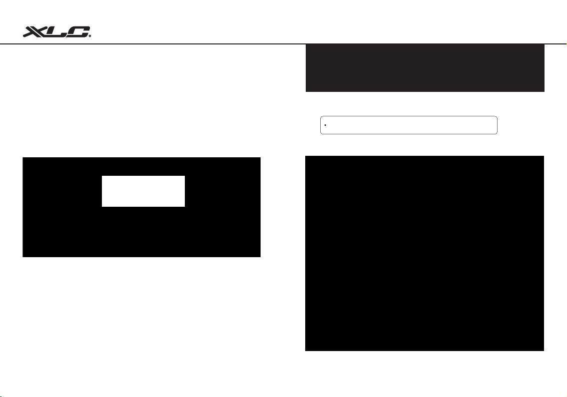
Under WHEEL SIZE
• Press A key or C key to adjust number
• Press M to transfer next setting!
Under SET CLOCK
CY-533AC contains two bike setting, it allows the user to
use this device for two bikes with different wheel size.
To get the accurate result from the device for speed
value or other information, the wheel size must be
correct. Mark the symbol on the tire and ride one
circle. Then measure the length between two points
that result comes out. Or determine the wheel
circumference by the following equation:
Circumference (mm) = 2x3.14xR (inch) x2.54 (1 inch = 2.54 cm)
R=Radius in centimeter
Please also refer the “wheel size chart” on the last page to nd out the wheel
size.