Xmart OPTIMA-33 10K User manual

ENGLISH
Xmart Optima-33 10K / 20K
VER. 150805
USER MANUAL
OPTIMA-33 10K / 20K / 30K
3 Phases IN - 3 Phases Out
ONLINE-DOUBLE CONVERSION UPS
400/230V & 208/120V
Technical information on this manual is property of XMART .
This manual Information cannot be copied or distributed totally or partially without written approval of XMART.
XMART can introduce modifications in their products or manuals without further notice. .
XMART is not responsible of mistakes or missing information in this manual.
XMART is not responsible for wrong use a third part can do of this information.
Trademarks and logos in this manual are property of their owners.

USER MANUAL - OPTIMA-33 10K / 20K / 30K
www.xmart-ups.com 150805-OPTIMA-33 10K/20K/30K (ENGLISH) - 0
TABLE OF CONTENTS
1. SAFETY
2. AVAILABLE MODELS
3.- UPS INSTALLATION: SITE PLANING
SITE INSPECTION & INSTALLATION CONDITIONS
TOWER UPS INSTALLATION
EXTERNAL CIRCUIT BREAKERS & WIRING SELECTION
4.- UPS INSTALLATION: SINGLE UPS - TERMINAL BLOCK
UPS AC LINES CONFIGURATION
ACTERMINALBLOCKS
EXTERNAL BATTERY CONNECTION
5.- UPS INSTALLATION: PARALLEL UPS - TERMINAL BLOCK
GENERALCOMMENTS
UPS AC LINES CONNECTION
PARALLEL CONTROL CABLES CONNECTION
6.- START-UP: SINGLE UPS
INSPECTION BEFORE START-UP
SINGLE UPS - START UP PROCEDURE
7.- START-UP: PARALLEL UPS
REQUIREMENTS FOR PARALLEL UPS SYSTEMS
INSPECTION BEFORE START-UP
PARALLL UPS - START UP PROCEDURE
8.- OPERATION INTERFACE
FRONT PÀNEL: PUSH BUTTONS / LEDS / LCD
9.- OPERATION: SINGLE UPS
10.- OPERATION: PARALLEL UPS
REMOVING UPS FROM PARALLEL SYSTEM
ADDING UPS TO PARALLEL SYSTEM
11.- UPS CONFIGUIRATION
12.- ERROR CODES, ALARMS & TROUBLESHOOTING
13.- TECHNICAL SPECIFICATIONS
14.- LIMITED WARRANTY

USER MANUAL - OPTIMA-33 10K / 20K / 30K
www.xmart-ups.com 150805-OPTIMA-33 10K/20K/30K (ENGLISH) - 1
1.GENERALSAFETYINSTRUCTIONS
WARNING: It is required to read and understand this manual. Follow all instructions given in this manual for starting up and
operating this product. Only qualified technician must start-up, operate and maintain this product. Keep manuals as a guide for
future consults.
WARNING: This product operates with dangerous voltages. It must be installed, operated and maintained ONLY by qualified
technicians trained for this kind of products. Service personnel MUST know and understand very well all electric risks related to
this product. UPS manufacturer or distributor will never be responsible for any accident produced by lack of knowledge or
negligent practices at the moment of install, starting up or maintain this product.
UPS manufacturer or distributor is not liable for any damage that might rise from misusing this unit or defective installation.
WARNING: If you are not qualified technician do not try to install, operate or repair this product.
WARNING: Do not try to install, operate or repair this product if you are not accompanied by another qualified person able to offer
first aid support in case of emergency or accidents.
WARNING: Internal area of this product is locked by screws. Do not try to access inside the UPS unless you are a qualified
technician. UPS must be checked, repaired and maintained by qualified personnel only.
CAUTION!!: ELECTRIC SHOCK RISK
CAUTION: There are dangerous voltages in the UPS power outlets although the equipment is not plugged to power line.
CAUTION: Inside this equipment, due to internal batteries, there are ALWAYS dangerous voltages, thought the UPS is OFF and
unplugged of power line.
CAUTION: There are dangerous voltages in DC (Direct Current) Capacitors. Please Check Capacitor location in Figure 8.4.1. Wait
at least 10 minutes after turning off UPS before opening it to access inside.
DANGER: Power off UPS and unplugged it from AC Line before opening it to Access inside this unit.
CAUTION: Before starting the opening procedure, remove all jewelry and metallic objects such as: Rings, Watches, Bracelets,
etc., because they could contact conductive parts and components inside the UPS and this might cause discharges and/or short
circuits. Make sure using tools properly isolated to avoid electrical risks.
Transportation and Storage: Warnings and Recommendations
WARNING: This UPS must be transported only in its original package to be properly protected
WARNING: This equipment must be storage in dry and ventilated site, in upright position.
WARNING: Before storage this UPS, batteries must be recharged for 8 to 10 hours
WARNING: During long term storage UPS must be recharged periodically according to this manual.

USER MANUAL - OPTIMA-33 10K / 20K / 30K
www.xmart-ups.com 150805-OPTIMA-33 10K/20K/30K (ENGLISH) - 2
•To enlarge batteries life expectancy it is recommendable to fully discharge UPS one every 2 to 3 months
•During UPS storage recharge batteries according to the following table:
WARNING: EQUIPMENT DISPOSAL
Out of service units : It is strongly recommended to dispose this piece of equipment according to valid directives in your
country. At the moment of disposing all pieces need to be managed appropriately to avoid possible environmental damage or for
some materials to be recycled.
Batteries : Do not throw it to fire (risk of explosion). Do not open the batteries, there are dangerous liquids inside
WARNING: BATTERIES MAINTENANCE
•Batteries capacity, in general (of all kinds), decrease with time and use.
•Our products contain high quality batteries only.
•Batteries useful life in our UPS is between 4 and 5 years, considering environment temperature under 25 ºC and optimal
operational conditions. This time can be dramatically reduced by high temperature and other adverse operation
condition.
•Batteries life expectancy may be also affected by other operation conditions such as electrical service quality as well as
number and kind of equipments connected to UPS
•Batteries should be periodically tested to check capacity and assure and appropriate back up.
Storage Temperature Recharging Frequency Recharging Time
-25°C a +30°C Every 4 months During 6 hours
+30°C a +45°C Every 2 months During 6 hours
SAFETYSTANDARDS
SAFETY: IEC/EN 62040-1
EMI (Radiated): FCC part15, Subpart B (Class A)
EMI (Radiated): IEC/EN 62040-2 (Cat 3)
EMI (Conducted): IEC/EN 62040-2 (Cat 3)
SURGE IMMUNITY IEEE / ANSI C62.41 (Cat A & B)
EMS Power-Frequency Magnetic Field: IEC/EN 61000-4-8 (Level 4)
EMS Low Freq. Signals: IEC/EN 61000-2-2
EMS (ESD): IEC/EN 61000-4-2 (Level 4)
EMS (RS): IEC/EN 61000-4-3 (Level 3)
EMS (EFT): IEC/EN 61000-4-4 (Level 4)
EMS (SURGE): IEC/EN 61000-4-5 (Level 4)
EMS (CS): IEC/EN 61000-4-6 (Level 3)
TRANSPORTATION: ISTA 1A
This product has been designed to operate in industrial and commercial applications. If it is used in different application some
considerations for avoiding interferences could be necessary.

USER MANUAL - OPTIMA-33 10K / 20K / 30K
www.xmart-ups.com 150805-OPTIMA-33 10K/20K/30K (ENGLISH) - 3
2.- AVAILABLE MODELS
OPTIMA-33 10K / 20K / 30K - 400/230V
UPS 3 phases IN & 3 phases OUT for 400/230V systems. Usually this kind of UPS include electronic and internal batteries in
same UPS cabinet.
OPTIMA-33 10K / 20K / 30K - 208/120V
UPS 3 phases IN & 3 phases OUT for 208/120V systems. It is based on 400/230V model but including internal transformers
to adjust external voltage values to internal working values.
UPS cabinet includes all electronic and I/O transformers. Batteries are located in dedicated external battery cabinet.
EXBATT BATTERY CABINETS
If external batteries are required for 230/120V models or for extending runtime, EXBATT external batteries can be connected
directly to the UPS.
EXBATT-33-T10K:
EXBATT for OPTIMA-33 10K. Includes 20 batteries 12V/9AH with DC breaker 50Amps.
DC voltage: 240Vdc (nominal).
EXBATT-33-T20K:
EXBATT for OPTIMA-33 20K. Includes 40 batteries 12V/9AH with DC breaker 100Amps.
DC voltage: 240Vdc (nominal).
EXBATT-33-T30K:
EXBATT for EPRO-33 30K. Includes 60 batteries 12V/9AH with DC breaker 150Amps.
DC voltage: 240Vdc (nominal).
WARNING
External battery packs for OPTIMA-33 models could be not compatible with some other OPTIMA UPS models.
Make sure you will connect compatible external battery pack to your UPS to avoid permanent damages not covered by
warranty.

USER MANUAL - OPTIMA-33 10K / 20K / 30K
www.xmart-ups.com 150805-OPTIMA-33 10K/20K/30K (ENGLISH) - 4
REARPANEL
1.- RS232 7.- FAN for power stage / Ventilación Forzada etapa de potencia
2.- USB 8.- EXBATT connector / Conector Baterías Externas
3.- EPO (Emergency Stop / Parada Emergencia) 9.- AC Input Breaker / Breaker de Entrada AC
4.- Share Current (for parallel UPS / para UPS paralelas) 10.- Terminal block cover / Tapa Regleta Conexiones
5.- Parallel Port (for parallel UPS / para UPS paralelas) 11.- MBS (Bypass Switch / Interruptor Bypass)
6.- Smart port / Puerto Inteligente 12.- FAN for TX (Ventilación del transformador)
MODEL: 208 / 120 VAC MODEL: 400 / 230 VAC

USER MANUAL - OPTIMA-33 10K / 20K / 30K
www.xmart-ups.com 150805-OPTIMA-33 10K/20K/30K (ENGLISH) - 5
3.-UPSINSTALLATION:SITEPLANNING
SAFETY INSTRUCTIONS
WARNING: Before revising this section you must read and understand very well section 1 of this manual: “GENERAL SAFETY
INSTRUCTIONS”.
WARNINGS, RECOMMENDATIONS AND LIABILITY LIMITATION
REACH AND LIABILITY LIMITATION: The preparation of the site, wiring and all protection devices must be supplied by end user and it will not
be responsibility neither the UPS distributor nor the UPS technician in charge of the start-up.
The place will be conditioned be end user or electrical contractor and must fulfill with local normative and directives and UPS technical
requirements.
This manual describes minimal conditions and technical requirements with which the site must accomplish.
Directives and requirements described in this manual, do not pretend to substitute in any way local electrical directives or normative.
In some cases, local directives or regulations might be more exigent than UPS technical requirements described by this manual. In that case
end user electrical contractor must be sure to comply with all related local electrical regulations and directives.
WARNING: Power lines must be protected by protection devices against over current (breakers) or leak currents with capacity and technology
appropriate to effectively accomplish its function. Moreover, installation grounding must be correct.
WARNING: Install the UPS in well ventilated locations and leave room enough between UPS and close objects and structures
WARNING: Do not connect to UPS equipments or devices that exceed its capacity, this would overload the UPS.
WARNING: This product has been designed to be used indoors protected from water, direct sun light, dust and extreme temperature.
WARNING: Do not put any object on the UPS; do not apply any force over UPS. Do not cover UPS ventilation.
WARNING: This UPS must be connected to appropriate electrical service according to selected model. Technical specs sticker in the UPS
shows the UPS power ratings. DO NOT connect this UPS to any of its own power outlets, this could damage the unit permanently.
WARNING: Do not connect AC motor based equipments without a careful sizing of the UPS based on inrush current instead of average current.
Inrush current typical of motor based system could overload this UPS.

USER MANUAL - OPTIMA-33 10K / 20K / 30K
www.xmart-ups.com 150805-OPTIMA-33 10K/20K/30K (ENGLISH) - 6
SITE INSPECTION AND INSTALLATION CONDITIONS
REGULATIONS AND LEGAL DIRECTIVES
It is necessary to check that installation site, wiring and power protection in the installation supplied by end user, fulfill technical parameters
required by UPS.
A particular installation might accomplish with UPS requirements but not with local directives and regulations.
The end user and/or electrical contractor will be responsible of watching for complying with electrical regulations and normative during electrical
installation managed by end user.
Inspection performed by installation technician is not intended to confirm regulations and directives accomplishing but only with technical needs
for optimal UPS operation.
SITE INSPECTION
•During transport of this UPS from a cold place to a warmer and more humid one, some condensation could be generated. Leave the
UPS for at least 2 hours to climate to new installation site.
•Do not install the UPS outdoors or near water sources nor in wet environment
•Do not install the UPS in sites exposed to sun light or heat sources. Temperature at operation site should never rise over 35 ºC.
Batteries’ life shortens over 25 ºC.
•Installation site must be dry, fresh, free of dust, fibers and any other objects (conductors or not) suspended in the air that could get
into the UPS thru the ventilation system (Fan).
•Do not block UPS ventilations
UPS INPUT AND OUTPUT POWER LINES PROTECTION
AC LINES PROTECTIONS DEVICES:
All UPS Inputs and outputs must be protected by circuit breakers and current leak protections. Protection capacity and type must fulfill local
regulations as well as directives from this manual. Grounding must be according to local directives as well.
DC PROTECTIONS DEVICES:
For Ex models (with external batteries) there must be also DC Circuit Breakers between UPS and battery bank.
Some Models include a DC breaker on the rear panel for external battery pack protection; otherwise an external DC Circuit breaker must be
installed.
MATERIALS AND ELECTRICAL DEVICES
WARNING: Verify that all electrical lines involved in installation are open circuits and free of dangerous voltages before starting inspection
tasks. All switches related to these electrical lines must be in “OFF” position before starting UPS installation. After disconnecting power from
electrical lines involved in installation, check again with a digital voltmeter that are free of dangerous voltages.
IMPORTANT: Warning label must be placed on primary involved circuit breakers to alert there are maintenance personnel working on these
circuits to avoid accidental actuation on involved breakers.

USER MANUAL - OPTIMA-33 10K / 20K / 30K
www.xmart-ups.com 150805-OPTIMA-33 10K/20K/30K (ENGLISH) - 7
TOWERUPSINSTALLATION
SITE CONSIDERATIONS
* This product has been designed to be used indoors, protected from water, direct sun light, dust and extreme temperature.
* Install the UPS in well ventilated location or air conditioned room. Temperature must be always in acceptable range according to technical
specifications table of this manual. It is strongly recommendable controlled room temperature between 21ºC to 24ºC for longer battery and UPS
life.
* There must be minimum 1 meter free room distance between UPS and any wall or object. It will allow better ventilation and it will allow
service UPS when required.
* Do not put any object on the UPS; do not apply any force over UPS. Do not cover UPS ventilation.
ELECTRICAL REQUIREMENTS (MANDATORY)
* All Power lines must be protected by magneto-thermal protection devices against over current (breakers) with capacity and technology
appropriate to effectively accomplish its function as indicated in this manual. Moreover, installation grounding must be correct.
* This UPS must be connected to appropriate electrical service according to selected model. Technical specs sticker in the UPS shows the UPS
power ratings. DO NOT connect this UPS to any of its own power outlets, this could damage the unit permanently.
* If external battery cabinets are connected to UPS, it is necessary to install one DC breaker between UPS and each external battery cabinet.
Original External Battery cabinets normally include its own input breaker.
LEAK CURRENT PROTECTION
In many countries, now a day, it is legally required to install protections against current leakage to protect human beings in cases of leaks o
discharges to ground. It is responsibility of the end user and/or electrical contractor selecting and including these protection devices in the
electrical circuit of the UPS.

USER MANUAL - OPTIMA-33 10K / 20K / 30K
www.xmart-ups.com 150805-OPTIMA-33 10K/20K/30K (ENGLISH) - 8
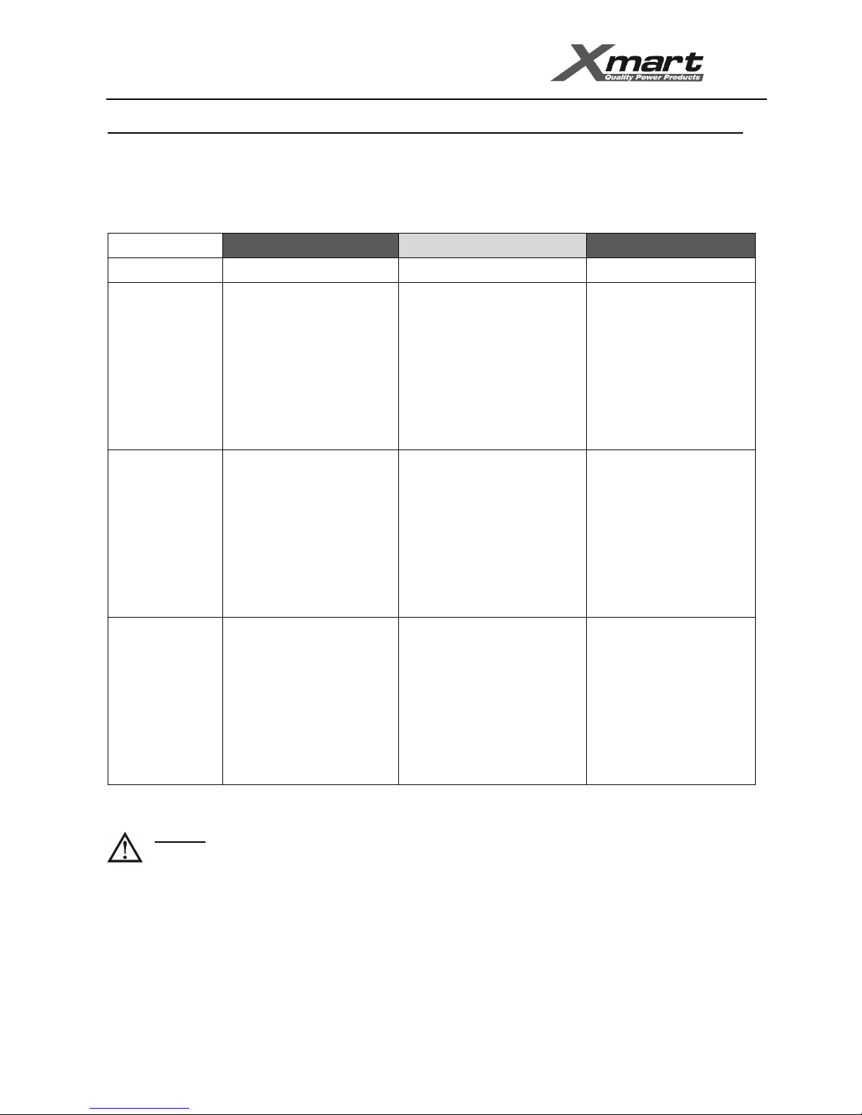
CIRCUITBREAKERSANDWIRINGSELECTION
Breakers and Gauge of the wires used in the installation must be rated to drive current values in Amps as indicated in below tables.
NOTE every country has its local electrical requirements and regulations. If local electrical regulations require higher rates than suggested values
in this section, please follow local regulations.
400/230VAC INPUT OUTPUT EXT. BATT
MODEL BREAKER & WIRING BREAKER & WIRING BREAKER & WIRING
10KVA
(400/230VAC)
Breaker: 32A AC (Curve D)
Max. Nominal Current (Ph-N):
- 19A in normal mode (@200V)
Wiring (min. recommended size):
* Phase: 10AWG (6 mm2)
* Neutral: 8AWG (10 mm2)
* Ground: 8AWG (10 mm2)
Breaker: 32A AC (Curve D)
Max. Nominal Current (Ph-N):
- 15A in normal mode (@220V)
Wiring (min. recommended size):
* Phase: 10AWG (6 mm2)
* Neutral: 8AWG (10 mm2)
* Ground: 8AWG (10 mm2)
Breaker: 50Amps DC (Curve C)
Wiring (min. recommended size):
* 8 AWG (10mm2)
20KVA
(400/230VAC)
Breaker: 50 Amps AC (Curve D)
Max. Nominal Current (Ph-N):
- 38A in normal mode (@200V)
Wiring (min. recommended size):
* Phase: 8 AWG (10 mm2)
* Neutral: 6 AWG (16 mm2)
* Ground: 6 AWG (16 mm2)
Breaker: 50 Amps AC (Curve D) Max.
Nominal Current (Ph-N):
- 30A in normal mode (@220V)
Wiring (min. recommended size):
* Phase: 8 AWG (10 mm2)
* Neutral: 6 AWG (16 mm2)
* Ground: 6 AWG (16 mm2)
Breaker: 100Amps DC (Curve C)
Wiring (min. recommended size):
* 6 AWG (16mm2)
30KVA
(400/230VAC)
Breaker: 63 Amps AC (Curve D)
Max. Nominal Current (Ph-N):
-56A in normal mode (@200V)
Wiring (min. recommended size):
* Phase: 8 AWG (10 mm2)
* Neutral: 6 AWG (16 mm2)
* Ground: 6 AWG (16 mm2)
Breaker: 63 Amps AC (Curve D) Max.
Nominal Current (Ph-N):
-45A in normal mode (@220V)
Wiring (min. recommended size):
* Phase: 8 AWG (10 mm2)
* Neutral: 6 AWG (16 mm2)
* Ground: 6 AWG (16 mm2)
Breaker: 150Amps DC (Curve C)
Wiring (min. recommended size):
* 3 AWG (35mm2)
Recommended cable size according to 1999 NEC (301-17) based on 30ºC air ambient temperature for single cable.
WARNING:
Above wiring and breakers rates are only a suggestion. The wire size is strongly affected by diverse factors such as: Operation
temperature, wire length, type of wire, quantity of conductors and kind of installation. Electrical contractor must assure an
appropriate selection for wire and protection devices sizing for complying with local regulations for electrical installations. Wiring
colors must be selected according to local directives and regulations

USER MANUAL - OPTIMA-33 10K / 20K / 30K
www.xmart-ups.com 150805-OPTIMA-33 10K/20K/30K (ENGLISH) - 9
208/120VAC INPUT OUTPUT EXT. BATT
10KVA
(208/120VAC)
Breaker: 63 Amps AC (Curve D)
Max. Nominal Current (Ph-N):
- 38A in normal mode (@100V)
Wiring (min. recommended size):
Phase: 8 AWG (10 mm2)
Neutral: 6 AWG (16 mm2)
Ground: 6 AWG (16 mm2)
Breaker: 63 Amps AC (Curve D)
Max. Nominal Current (Ph-N):
- 30A in normal mode (@110V)
Wiring (min. recommended size):
Phase: 8 AWG (10 mm2)
Neutral: 6 AWG (16 mm2)
Ground: 6 AWG (16 mm2)
Breaker: 50 Amps DC (Curve C)
Wiring (min. recommended size):
8 AWG (10mm2)
20KVA
(208/120VAC)
Breaker: 80 Amps AC (Curve D)
Max. Nominal Current (Ph-N):
- 75A in normal mode (@100V)
Wiring (min. recommended size):
Phase: 6 AWG (16 mm2)
Neutral: 4 AWG (25 mm2)
Ground: 4 AWG (25 mm2)
Breaker: 80 Amps AC (Curve D)
Max. Nominal Current (Ph-N):
- 60A in normal mode (@110V)
Wiring (min. recommended size):
Phase: 6 AWG (16 mm2)
Neutral: 4 AWG (25 mm2)
Ground: 4 AWG (25 mm2)
Breaker: 100Amps DC (Curve C)
Wiring (min. recommended size):
* 6 AWG (16mm2)
30KVA
(208/120VAC)
Breaker: 125 Amps AC (Curve D)
Max. Nominal Current (Ph-N):
- 111A in normal mode (@100V)
Wiring (min. recommended size):
Phase: 3 AWG (35 mm2)
Neutral: 2 AWG (35 mm2)
Ground: 2 AWG (35 mm2)
Breaker: 125 Amps AC (Curve D) Max.
Nominal Current (Ph-N):
- 90A in normal mode (@110V)
Wiring (min. recommended size):
Phase: 3 AWG (35 mm2)
Neutral: 2 AWG (35 mm2)
Ground: 2 AWG (35 mm2)
Breaker: 150Amps DC (Curve C)
Wiring (min. recommended size):
* 3 AWG (35mm2)
Recommended cable size according to 1999 NEC (301-17) based on 30ºC air ambient temperature for single cable.
WARNING:
Above wiring and breakers rates are only a suggestion. The wire size is strongly affected by diverse factors such as: Operation
temperature, wire length, type of wire, quantity of conductors and kind of installation. Electrical contractor must assure an
appropriate selection for wire and protection devices sizing for complying with local regulations for electrical installations. Wiring
colors must be selected according to local directives and regulations

USER MANUAL - OPTIMA-33 10K / 20K / 30K
www.xmart-ups.com 150805-OPTIMA-33 10K/20K/30K (ENGLISH) - 10
4.- UPS INSTALLATION: SINGLE UPS - TERMINAL BLOCK
ACLINESCONNECTIONPROCEDURE
• Make sure the UPS is Off before starting the installation.
• Remember to check all wires to be connected are not powered (including external batteries).
UPS terminal block preparation
Remove cover of terminal block at the UPS rear panel.
UPS Input wires must come from electric panel board and they must be protected by a circuit breaker protection device.
Connect input and output ground wires to the UPS chassis or terminal block. Ground wires must be FIRST to be connected and LAST to be
disconnected. Connect UPS input and output wires according to your UPS model as described in following figures.
IMPORTANT NOTE: If terminal block information printed on rear panel of the UPS is different to information given in this manual,
please follow terminal block information printed on UPS.
OPTIMA-33 208/120VAC
OPTIMA-33 400/230VAC

USER MANUAL - OPTIMA-33 10K / 20K / 30K
www.xmart-ups.com 150805-OPTIMA-33 10K/20K/30K (ENGLISH) - 11
EXTERNAL BATTERY CABINETS – CONNECTION PROCEDURE
UPS Tower type
WARNING
Make sure EXBATT model to be connected is compatible with UPS model. For OPTIMA-33 models, battery pack voltage is 240Vdc.
Measure and verify DC voltage supplied by battery pack before making connections.
1.- Check all DC breakers are in OFF position
2.- Remove all DC connector covers in UPS and EXBATT cabinets
3.- Using appropriate cable (supplied with the EXBATT) connect UPS with EXBATT 1. In case of more than 1 EXBATT connect EXBATT 1 with
EXBATT 2 and so on until last EXBATT.
4.- Activate DC breakers one by one in EXBATT cabinets to connect EXBATT batteries with internal UPS Main batteries.

USER MANUAL - OPTIMA-33 10K / 20K / 30K
www.xmart-ups.com 150805-OPTIMA-33 10K/20K/30K (ENGLISH) - 12
5.- UPS INSTALLATION: PARALLEL UPS - TERMINAL BLOCK
GENERALCOMMENTSFORPARALLELSYSTEMS
* Parallel Installation allow up to 3 units in parallel.
* All units must have similar control board firmware version. If all UPS belong to same manufacturing batch, firmware will be the same. If
units below to different manufacturing batches, please contact your distributor to ask about compatibility to connect in parallel.
* All units in parallel must be configured with same parameters.
* Units to work in parallel must be connected as indicated in this section.
* Parallel system must be configured and started up according to instructions given dedicated section of this manual.
* Any mistake in connection, configuration or starting up procedure could produce permanent damage UPS
PARALLEL UPS CONNECTION
• Make sure the UPS is Off before starting the installation
• Remember to check all wires to be connected (including external batteries)
are not powered before manipulating them.
UPSTERMINALBLOCKPREPARATION
Remove cover of terminal block at the UPS rear panel, identified as 10 in rear panel section of this manual
UPSINPUTANDOUTPUTCONNECTIONS
Connect input and output ground wires to proper place on the UPS chassis on both sides of terminal blocks. Ground wires must be FIRST to be
connected and LAST to be disconnected. Refer to below figure.
a) Grounding Wires: Connect AC Input and Output ground of both UPS according to figures.
b) AC Input Wires: AC Input wires must come from individual electrical circuit breakers on electrical panel board before being connected
to UPS terminal block.
c) AC Output Wires: AC output wires must be connected directly to external circuit breakers of bigger capacity.
d) If UPS is EX model, external battery banks must be connected to dedicated connector located in rear panel of UPS.
e) Control Cables for Parallel Connection: Connect Parallel Cable and shared current according to figures.
WARNING – EXTERNAL BATTERIES:
If UPS to be connected in parallel have external batteries it is mandatory each UPS counts with its own battery pack. Parallel
connection cannot be performed if only one of two (or two or three) UPS have external batteries. Permanent damages will be
produced in UPS if this warning is not followed.

USER MANUAL - OPTIMA-33 10K / 20K / 30K
www.xmart-ups.com 150805-OPTIMA-33 10K/20K/30K (ENGLISH) - 13
PARALLEL-TERMINALBLOCKWIRING

USER MANUAL - OPTIMA-33 10K / 20K / 30K
www.xmart-ups.com 150805-OPTIMA-33 10K/20K/30K (ENGLISH) - 14
PARALLEL-CONTROLCABLES

USER MANUAL - OPTIMA-33 10K / 20K / 30K
www.xmart-ups.com 150805-OPTIMA-33 10K/20K/30K (ENGLISH) - 15
6.-START-UP:SINGLEUPS
INSPECTIONBEFORESTARTUP
1. Make sure all wires are tightly connected to terminal block. Any loose connection will produce overheating, failures and damage to
UPS.
2. Make sure all instructions of sections 3 and 4 have been performed correctly.
3. Put the terminal block cover back in its position to avoid access to wiring.
4. Check EPO connections.
•EPO Port closed (Wired): EPO function disabled
•EPO port connected to an emergency switch: EPO function available by activation of Emergency Switch; which must be
“Normally Closed” type in order to guarantee that UPS will shut down when circuit opens.
5. Check Maintenance Bypass Switch (MBS) located in UPS rear panel is in UPS position and its cover is duly installed.
6. Make sure all external protection devices in input and output lines are in open (OFF) position.
SINGLEUPS-STARTUPPROCEDURE
1. Make sure all equipments connected to UPS are off
2. Power AC input at electrical panel board by setting input AC Lines Circuit Breaker to ON
3. Put Battery Bank breaker to ON (Only for Ex Models, If using external battery pack)
4. Put AC INPUT Breaker to ON in UPS rear panel.
5. LCD in front panel starts to show bypass mode. UPS Outputs are powered although UPS is off because it is on By-Pass mode. At this
moment output power is being supplied by AC Input Power Line.
6. Start up the UPS by pressing On push button in front panel until beep is heard and ON message displayed on top of the LCD.
7. Few seconds after, the UPS leaves By-Pass mode to enter in Normal Online Mode, also known as “AC Mode”
8. Power on sequentially each equipment connected to UPS output. The front panel LCD should show the load increase as equipments
start.
9. Once all equipments are on, the total power consumption (load) should not exceed UPS capacity.
10. At this moment UPS working under NORMAL AC-MODE and the system is supplied by UPS.
NOTE 1: If any error or warning message in indicated in LCD please revise Troubleshooting section of this manual.
NOTE 2: UPS batteries maybe are not fully charged. UPS could require about 4 to 6 hours to recharge batteries up to 100% of their
capacity.

USER MANUAL - OPTIMA-33 10K / 20K / 30K
www.xmart-ups.com 150805-OPTIMA-33 10K/20K/30K (ENGLISH) - 16
7.-START-UP:PARALLELUPS
REQUIREMENTSFORPARALLELSYSTEM
WARNING: Before starting up this parallel UPS system is mandatory to comply with all below requirements.
1.- Maximum quantity of UPS to be connected in parallel is 3. Do not try to connect more than 3 units in parallel.
2.- All UPS to be connected in parallel system must be same model with same firmware version. Please ask your distributor to confirm
firmware is the same in case of doubts. UPS belonging to same manufacturing batch have same firmware version.
3.- UPS configuration (configuration parameters of LCD menu) must be the same for all UPS.
4.- MBS (Maintenance Bypass Switch) located in all rear panels must be in "UPS" position and switch covers must be properly installed.
5.- In case of using external battery packs, each UPS must has same external battery packs quantity and type.
6.- All control parallel cables (parallel cables and current share cables) must be properly connected in UPS rear panels as indicated in section
5 of this manual.
7.- Make sure total available capacity (in Watts) of all UPS to be connected in parallel is higher than load to be connected to UPS system. It is
recommendable total UPS power is at least 25% higher to total load. If UPS system will work as n+1 redundant system, make sure total
UPS capacity after removing one UPS is higher than maximum load to be connected. If not remaining UPS will not be able to support
connected load when one of the units was removed.
INSPECTIONBEFORESTARTUP
1. Make sure all wires are tightly connected to terminal block. Any loose connection will produce overheating, failures and damage to UPS.
2. Make sure all instructions of sections 3 and 5 have been performed correctly.
3. Put the terminal block cover back in its position to avoid access to wiring
4. Check EPO connections.
•EPO Port closed (Wired): EPO function disabled
•EPO port connected to an emergency switch: EPO function available by activation of Emergency Switch; which must be “Normally
Closed” type in order to guarantee that UPS will shut down when circuit opens.
5. Check Maintenance Bypass Switch (MBS) located in UPS rear panel is in UPS position and its cover is duly installed.
6. Make sure all external protection devices in input and output lines are in open (OFF) position.
7. Check control parallel cables are connected according to section 5 of this manual.

USER MANUAL - OPTIMA-33 10K / 20K / 30K
www.xmart-ups.com 150805-OPTIMA-33 10K/20K/30K (ENGLISH) - 17
STARTUPFORPARALLELUPSSYSTEM
WARNING: Make sure all requirements and previous inspection have been revised and complied before initiating start up procedure. If
not please do not try to continue with start-up procedure.
1.- Make sure all equipments to be protected and connected to UPS output are in OFF condition.
2.- Check AC input breaker located in UPS rear panels is in OFF position in all UPS of the system.
3.- Power on external main AC input in electrical panel. Set to ON position all external AC input breakers.
4.- If UPS are using external battery packs, set to ON all DC breakers to connect external DC packs to UPS.
5.- For UPS No. 1: Set to "ON" AC input breaker located in rear panel of UPS No. 1. Wait until UPS No.1 completes auto-checking and Bypass
LED lights continuously.
6.- For UPS No. 2: Set to "ON" AC input breaker located in rear panel of UPS No. 2. Wait until UPS No.2 completes auto-checking and Bypass
LED lights continuously.
7.-In case of having 3 UPS in the system, proceed in similar manner with UPS No. 3.
IMPORTANT: AC input breakers activation must be done in one by one and not at same time. First for UPS No. 1, then for UPS No. 2 and
finally for UPS No. 3 (if you have a parallel system with 3 UPS). If AC input breakers are activated all at same time, warning message "3F"
could be activated. If it occurs, reinitiate procedure sequentially. Warning 3F message must be previously reset according to warning and
error section in this manual
8.- When rear panel AC breaker is set to "ON", This UPS recognizes all other UPS previously powered ON in the parallel system and will get
its own parallel identification as PAR 00X, where X is the position according to power on sequence. PAR 001 for 1st UPS powered on, PAR
002 for 2nd and PAR 003 for 3rd UPS.
This message is only indicated in UPS manufactured after Dec-2011. If UPs is before Dec-2011 continue without waiting for PAR 00X
message.
9.- At this moment all UPS LCDs must turn on to indicate internal circuitry in UPS is been powered.
** If bypass mode is allowed, all UPS will go to bypass mode.
** If bypass mode is not allowed by configuration, all UPS will go to a kind of stand-by mode with outputs open and powered off
waiting until ON command is selected in UPS front panel.
10.- At this moment configuration menu in each UPS LCD must be revised to select desired configuration. It is mandatory to use same
configuration in all configuration parameters for all UPS of the system.
11.- Once configuration has been selected and verified, all UPS can be started up by selecting "ON" push button in front panel. Please press
"ON" push button for each UPS. One long "beep" will be generated. "ON" message will be displayed on top side of LCD.
12.- All UPS will go to NORMAL Online mode at same time.
13.- Before setting to "ON" external output breakers please revise AC voltage output on each UPS.
** Please measure AC output voltage using a digital multi-meter and confirm all output voltages are similar. Maximum acceptable deviation
should be 3Vac or lower. Typically 1.5Vac.
** If difference between output voltage values is higher than 3Vac, we suggest to adjust them by function 15 (for inverter output L1),
function 16 (for inverter output L2) and function 17 (for inverter output L3). You can reduce (Sub) or increase (Add) voltage output voltage
for any of 3 inverters in each UPS as required.
14.- If AC output voltages are similar (lower than 3Vac), please set to "ON" external output breakers for all UPS progressively. Start with UPS
Nº 1, then UPS Nº 2, etc. After that, all UPS outputs are connected in parallel.
15. Check to confirm there are no error or alarm messages on LCDs. At this moment all UPS are working in NORMAL Online mode and
connected in parallel.
16.- It is time to power on equipments connected to UPS output. Power on progressively one by one. Check on UPS LCDs how power output
rises meanwhile equipments are powered on.
** Once all output load is connected check power output is below 100%.
** At this moment, UPS parallel system is powering your system in NORMAL Online mode.

USER MANUAL - OPTIMA-33 10K / 20K / 30K
www.xmart-ups.com 150805-OPTIMA-33 10K/20K/30K (ENGLISH) - 18
8.-OPERATIONINTERFACE
UPSFRONTPANEL:PUSHBUTTON
TOWER FRONT PANEL
ON / ENTER
POWER ON : Keep selected during 1 second to power UPS ON.
ENTER : It Works as “ENTER” or confirmation function when LCD is in configuration menu mode.
OFF / ESCAPE
POWER OFF : Keep selected to turn UPS OFF.
ESCAPE : It Works as ESCAPE key when LCD is in configuration menu mode.
TEST / UP
BATTERY TEST : When UPS is in normal mode by selecting TEST key UPS enters into battery test mode during 10 seconds.
UP : It Works as UP key when LCD is in configuration menu mode.
MUTE / DOWN
ALARM MUTE : It mutes alarm beep in progress.
DOWN : It Works as DOWN key when LCD is in configuration menu mode,
TEST / UP + MUTE / DOWN - Simultaneous Activation
CONFIGURATION MODE : UPS enters into configuration menu when these 2 keys are activated at same time during 1 second.
This manual suits for next models
2
Table of contents
Other Xmart UPS manuals

Xmart
Xmart OPTIMA RT9W 1K User manual

Xmart
Xmart Optima 6K User manual

Xmart
Xmart OPTIMA-RT10-10K User manual

Xmart
Xmart SUPRA 501 User manual

Xmart
Xmart OPTIMA-T09W-06K-230V User manual

Xmart
Xmart OPTIMA-RACK 1KVA User manual

Xmart
Xmart OPTIMA T09 1K User manual

Xmart
Xmart SUPRA 501 User manual

Xmart
Xmart Landscape Series User manual

Xmart
Xmart OPTIMA-31 10K User manual
Popular UPS manuals by other brands

CyberPower
CyberPower 649532815036 Specification sheet

LEGRAND
LEGRAND Keor SPE 750 Installation and user manual

Minuteman
Minuteman AT300 owner's manual

Emerson
Emerson Liebert HiPulse E Series Communications manual

Minuteman
Minuteman Enspire Series user manual

Eaton
Eaton Ellipse MAX 600 Installation and user manual