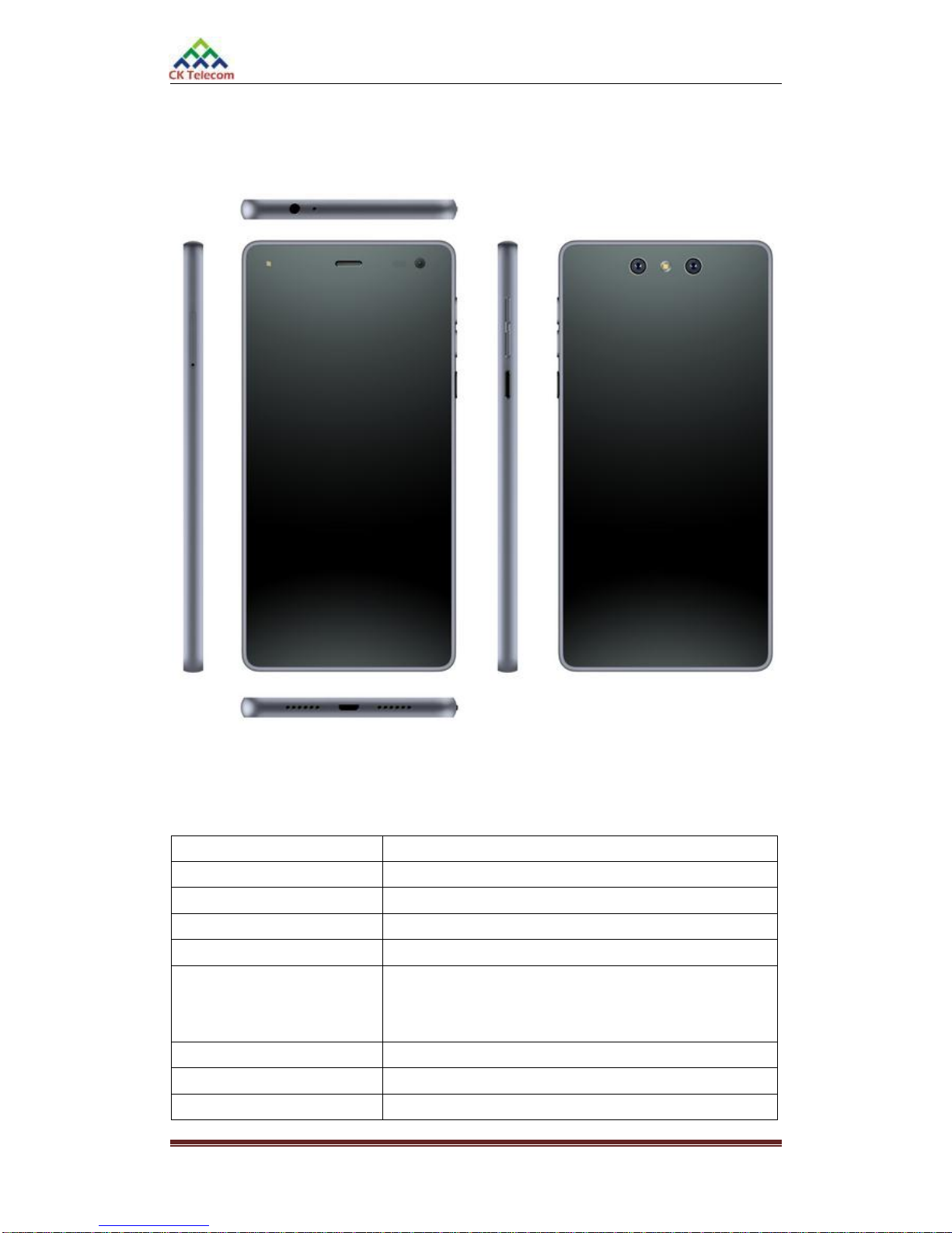
Mobile Phone Xolo Mirage Plus (Smartphone) Service Manual
Page 2of 40
CONTENT
CHAPTER 1: SUMMARY....................................................................................................................4
CHAPTER 2: PCBA OVERVIEW .......................................................................................................6
2.1 MIRAGE PLUS-TOP SIDE-LAYOUT.............................................................................................6
2.2 MIRAGE PLUS-BACK SIDE-LAYOUT .........................................................................................6
CHAPTER 3: EXPLANATION OF SCHEMATIC.............................................................................7
3.1 BASE BAND CHIP MSM8939 FEATURES..........................................................................................7
3.2 POWER MANAGER UNIT PM8916 INTRODUCTION...........................................................................8
3.3 RF CHIP WCN3620 DEVICE INTRODUCTION ...................................................................................9
3.4 INTERFACE FUNCTIONAL CIRCUIT.................................................................................................10
3.4.1 Charging Circuit....................................................................................................................10
3.4.2 Microphone Interface............................................................................................................10
3.4.3 Headset Interface...................................................................................................................11
3.4.4 Receiver Interface .................................................................................................................11
3.4.5 LCD Connector Interface......................................................................................................12
3.4.6 Camera Interface Circuit .......................................................................................................12
3.4.7 Key and RGB LED Circuit ...................................................................................................14
3.4.8 Sensor Interface.....................................................................................................................14
3.4.9 SIM Cart Tray Interface ........................................................................................................15
CHAPTER 4: MOBILE FAILURE ANALYSIS................................................................................16
4.1 POWER ON ISSUE ANALYSIS ...........................................................................................................17
4.2 DISPLAY ISSUE ANALYSIS...............................................................................................................18
4.3NO INCOMING &OUTGOING VOICE ISSUE ANALYSIS......................................................................19
4.4 HEADSET ISSUE ANALYSIS .............................................................................................................21
4.5 NO VOICE IN SPEAKER ISSUE ANALYSIS .........................................................................................22
4.6 FM ISSUE ANALYSIS.......................................................................................................................23
4.7 TOUCH SCREEN ISSUE ANALYSIS....................................................................................................24
4.8 CAMERA ISSUE ANALYSIS ..............................................................................................................25