XPR Access EWS-DR User guide

www.xprgroup.com
1
INSTALLER MANUAL
EN
EWSDR/ EWSi-DR
1. WIRING
2. SPECIFICATIONS
v.a2
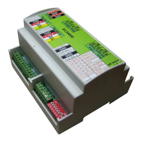
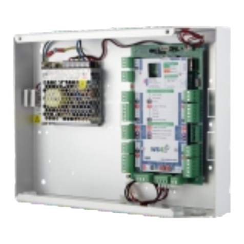
2 Doors/2 Readers Access Control Unit
Power Supply: 12VDC
User/Event capacity: 1000/30000, 4000/24000, 8000/16000, 12000/8000 or 15000/2500,
conigurable by software
Communication: EWSDR -RS485, EWSi-DR -RS485 and TCP/IP
Door relays: 2 (250 VAC, 10A)
Programmable Outputs: 2 (250 VAC, 10A)
Readers: 2
Programmable Inputs: 2, optocoupled, ON level 530VDC (328mA)
Door sensors: 2
Exit Button Inputs: 2
Wiegand interface: Programmable (8 to 128bit), 32databits, 4 parity bits
Environment temperature: 0 - 45 C
Humidity: 080%, non condensing
Consumption: EWSDR 200mA, EWSi-DR 250mA (without readers)
Fuse protection: 1A thermal fuse for total consumption of the controller and readers.

www.xprgroup.com
2
3. INSTALLATION
4. COMMUNICATION 5. MOUNTING THE PCB
6. RS485 TUNING
6. RS485 TUNING
1. Connect the devices according to the connection diagram above.
2. Use the diodes provided when the door lock is DC powered or the capacitor with 10K resistor when the lock is AC powered.
3. Use the Dipswitch pin1 for Rs485 tuning.
4. Insert the battery provided with the hardware kit.
5. Connect the power.
PCB can be mounted directly on the panel. In this case, use provided
spacers for ixing and printed screen for protection.
1 km max / 32 Units (EWS and Biometric Readers)
Put the Dipswitch pin1 in ON position, on the irst and last controller
in the RS 485 network, to set 120ohm resistance
between terminal pins A and B.
IMPORTANT NOTE:
- The RS485 Communication Line must be made in daisy chain, NOT in a star type coniguration.
- The cable must be twisted and shielded. Connect the EARTH to the shield.
- Connect the COM to each unit in the RS 485 line.
- Terminate both ends of the line with 120 Ohm resistor. If end of line is EWSDR, use built in resistor (120 ohm) by turning the Dipswitch pin1 ON.
With PROS CS:
The default IP of the controller is 192.168.1.100
To change the IP of the EWS controller:
1. Connect the EWS controller directly to the PC.
2. Change the IP of your PC to 192.168.1.200
3. Go in the Software and in the hardware window, right click on the Portals item, then select Search Network Portals. When the Search portals
window is opened, hit Search.
4.Click on the “Setup” button.
Setup Portal window is opened, and now you can set values for the parameters in the portal setup. Further you have the parameters of the setup
explained.

www.xprgroup.com
3
7. ADDING EWS(I)-DR CONTROLLER IN THE SOFTWARE
IP: Portal IP address.
Setup Port: Used for searching the portals of the network.
Password: For searching and coniguring the portals.
Mask: IP Mask.
Gateway: Network Gateway.
MAC: Mac portal.
DHCP enable: It is recommended that DHCP is disabled and ixed IP value is used.
DNS: Domain name server. Recommended to keep zeros.
Data port: Port value for communication between software and devices (controllers,
readers) connected to the portal.
Dedicated client: If enabled portal will connect only with software on computers that
are matching the dedicated IP or dedicated MAC value. This parameter aects only
communication between server software and portal. Computers that are running client
software are not aected, as client software is connected only to server software and not
with portals.
Dedicated IP: Valid if dedicated client is enabled.
Dedicated MAC: Valid if dedicated client is enabled.
Enable web interface: If enabled, portal coniguration can be done by web browser using
IP and Web port as an address.
(ex. If the port IP is 192.168.1.100 and Web port is 80, the web address for setup is
http://192.168.1.60:80 )
Version: Firmware version of the portal. If newer version is available, it will be distributed
with the latest release of the access control software.
5. Change the portal IP address, and press Send settings.
6. Put back the IP of your PC to the previous IP address.
With Web browser:
- Change the IP of your PC to 192.168.1.200
- Connect the EWS controller and type in the browser 192.168.1.100 ( username: admin, password: 00000000) and change the IP from there
- Put back the IP of your PC to the previous IP address
In order the controller to communicate with the software, the controller must be added in the software with its Serial Number. The serial Number is
written on the controller itself, but it can be also searched when the controller is connected to PC.
1. Right click on Portals and select “Search Network Portals”
2. The Software will ind all the IP’s of the controllers that are connected to the network
3. Click on “Add”
4. Right click on the newly added portal and “Search devices” for Controllers. The software will ind all the Serial Numbers of the controllers that are
connected under that IP address.
5. Click on “Add New” and the controller will be added. Put a name for the controller and “Save and Exit”. From then on the controller should be on line.

www.xprgroup.com
4
8. TROUBLESHOOTING
1. Reader is not reading the card.
-Check the power supply at reader. If the voltage is low use additional wires for power supply.
-Check the connection of the wires in EWSDR reader terminals.
-Check if the card type match the reader or the readers card type setup.
-Check for correct wiring.
2. Reader is reading the card, but no reaction from the controller or access event in the software.
-Check in software if readers Wiegand setting match the reader Wiegand output.
-Check if cable length is within the speciications of the reader. If reader is working with short cable then the problem is voltage drop on power
supply lines. In this case use free wires as additional power supply lines for the reader. If you have only one free wire use it to improve the 0V line.
3. Communication via RS 485 line is inconsistent or non-existing ( in the software, controller is switching online/oline status).
-Check if A and B lines are correctly connected at all terminals/devices.
-Check if one of the RS 485 lines is disconnected at some point.
-Check termination coniguration of RS 485 line in all devices.
4. Controller loses time and users after mains power failure.
-Replace the controller coin battery (Cr2032).
-Always use power supply with battery charger and battery of at least 4 Ah.
5. Software cannot connect to controller via TCP.
-Make sure there is no other device with the same IP address in the network.
-Make sure there is no other software communicating with the controllers.
-Check with the WEB interface of the EWSDR if the settings are correct.
6. Searching portals in software shows only some or none of the portals.
-In the software under settings/system parameters disable the item “use default PC network interface only’.
7. Controller does not perform some options conigured by software.
-Check the controller irmware by right-clicking on the controller icon and selecting “Check version item”. Upgrade the irmware by right-clicking
on the controller icon and select “Firmware upgrade item”.
This product herewith complies with requirements of EMC directive 2014/30/EU. In addition it complies with RoHS2 directive EN50581:2012
Note: If the Controller/Portal can not be added automatically by search option, add them manually.
For any other feature, see the HELP File located whithin the software itself
This manual suits for next models
1
Table of contents
Other XPR Access Control Unit manuals
Popular Control Unit manuals by other brands

Whelen Engineering Company
Whelen Engineering Company WeCan Series installation guide

Festo
Festo DeviceNet CMGA-E1-DN installation manual

Telit Wireless Solutions
Telit Wireless Solutions LN960 HW User Guide

Meyer Burger
Meyer Burger GB installation guide

Ring Engineering
Ring Engineering AM-1b user manual

National Instruments
National Instruments NI 9269 Getting started guide