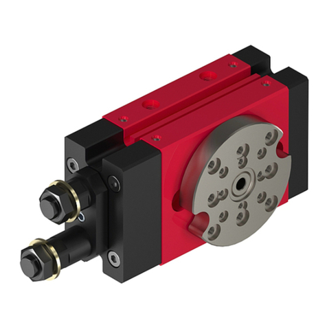
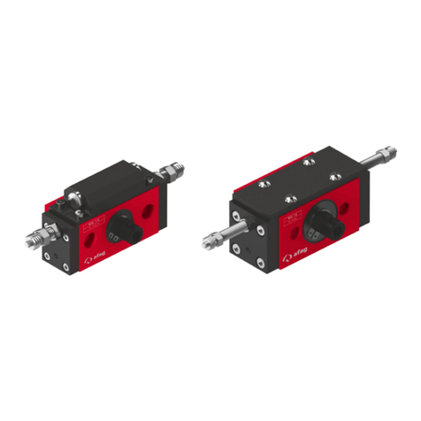
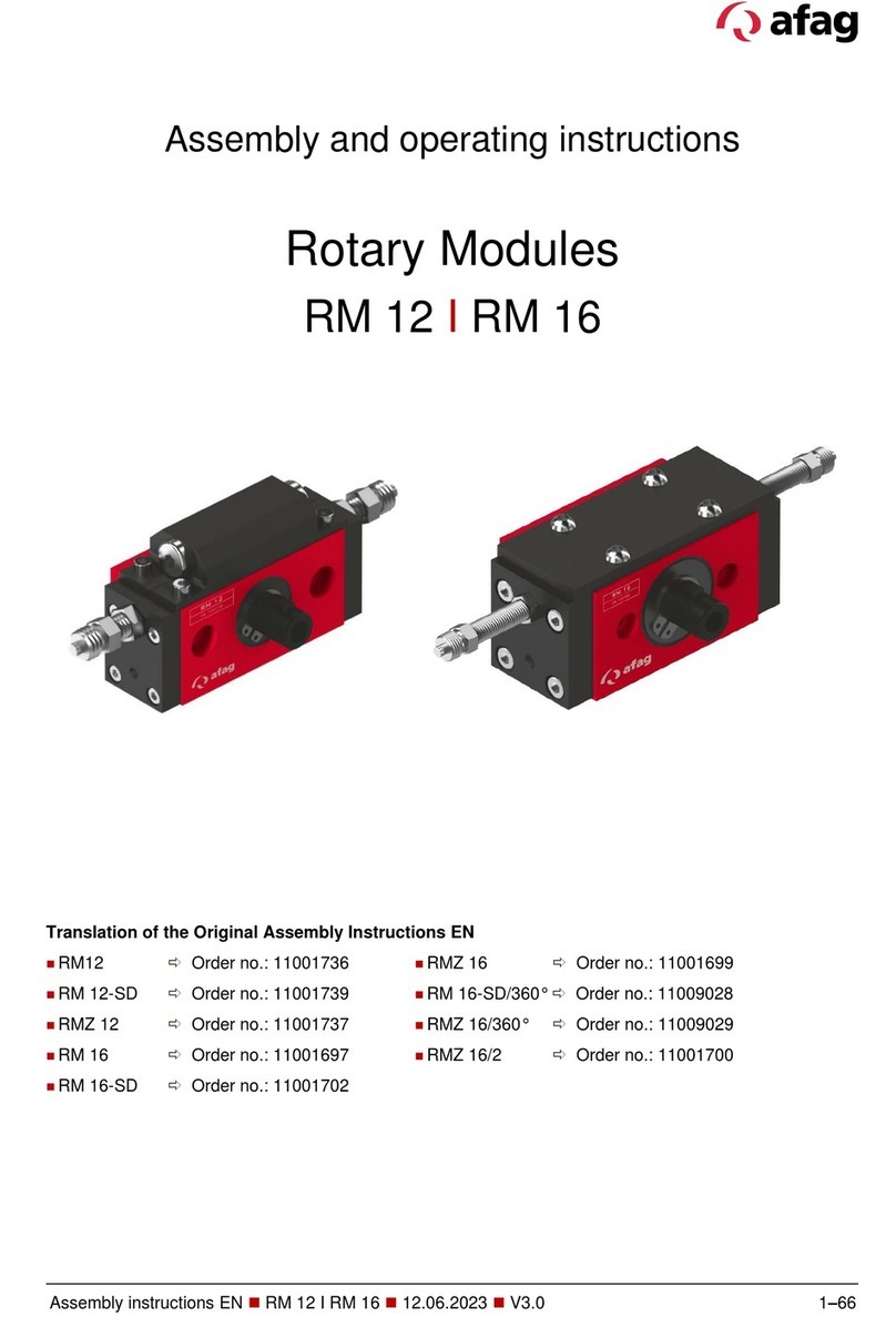
Afag RM 12 Technical specifications

Rotary module
RM 12 - RM 16
-
Declaration of Incorporation
-
Module Information
- Montage Instructions
- Maintenance Instructions
„Translation“ of the Original Montage Instructions
© Copyright by Afag Automation AG

2 RM 12- RM 16-OI-vers. 2.8 gb. 20190326
These Montage Instructions apply to:
Type Order No. Type Order No.
RM 12
RM 12-SD
RMZ 12
RM 16
RM 16-SD
11001736
11001739
11001737
11001697
11001702
RMZ 16
RM 16-SD/360°
RMZ 16/360°
RMZ 16/2
11001699
11009028
11009029
11001700
Version of this documentation: RM 12- RM 16-OI-vers. 2.8 gb. 20190326
Symbols: Assembly and initial start-up must be
carried out by qualified Personnel only
and according to these Montage
Instructions.
DANGER
Indicates an immediate threatening danger.
Non-compliance with this information can result in death or
serious personal
injuries (invalidity).
WARNING
Indicates a possible dangerous situation.
Non-compliance with this information can result in death or
serious personal injuries (invalidity).
CAUTION
Indicates a possibly dangerous situation.
Non-compliance with this information can result in damage to
property or light to medium personal injuries.
NOTE
Indicates general notes, useful operator tips and Installation
recommendations which don't affect safety and health of the
personnel.

RM 12- RM 16-OI-vers. 2.8 gb. 20190326 3
Table of contents
1.0.0 EC Declaration for Incorporation (Document original) ....................................... 5
1.1.0 According to: 2006/42/EC .............................................................................. 5
2.0.0 Module Information ............................................................................................ 6
2.1.0 Transport and storage (packing and unpacking) ............................................ 6
2.1.1 Possibilities of fastening RM 12 / RM 16 - Module ......................................... 7
2.1.2 Centering bushings ........................................................................................ 8
2.1.3 Tightening torques for screw .......................................................................... 9
2.1.4 Preferred combinations RM 12 .................................................................... 10
2.1.5 Preferred combinations RM 16 .................................................................... 11
3.0.0 Montage Instructions ....................................................................................... 12
3.1.0 Manufacturer address: ................................................................................. 12
3.1.1 Symbols ....................................................................................................... 13
3.1.2 General description ...................................................................................... 13
3.1.3 Description rotary module RM 12 ................................................................. 14
3.1.4 Description the rotary module RM 16 ........................................................... 16
3.1.5 Functional Description .................................................................................. 18
3.1.6 Included in the delivery ................................................................................ 20
3.1.7 Intended use ................................................................................................ 20
3.1.8 Warranty ...................................................................................................... 21
3.1.9 Areas of application ...................................................................................... 22
3.2.0 Dimension RM 12......................................................................................... 23
3.2.1 Technical data RM 12 .................................................................................. 24
3.2.2 Dimension RM 16 / RM 16-SD / RMZ 16 ..................................................... 25
3.2.3 Technical data RM 16 .................................................................................. 27
3.2.4 Dimension RM 16-SD/360° - RMZ 16/360° .................................................. 29
3.2.5 Technical data RM 16/360° .......................................................................... 30
3.2.6 Pneumatic schematically RM 12 .................................................................. 31
3.2.7 Pneumatic connections RM 16 .................................................................... 32
3.2.8 Pneumatic connections RMZ 16/2 ............................................................... 33
3.2.9 Preparation for start-up ................................................................................ 34
3.3.0 Rotation angle adjustment RM 12/ RM 16 .................................................. 35
3.3.1 Shock absorbers SD 08/06 .......................................................................... 37
3.3.2 Intermediate positions (not monitored) ......................................................... 39

4 RM 12- RM 16-OI-vers. 2.8 gb. 20190326
3.3.3 Intermediate position RMZ 16/2 (monitored) ................................................ 41
3.3.4 Proximity Switches ....................................................................................... 45
3.3.5 Mounting for proximity switch ....................................................................... 47
4.0.0 Maintenance instructions ................................................................................. 48
4.1.0 Maintenance and servicing of the RM 12 / RM 16 ....................................... 48
4.1.1 Servicing ...................................................................................................... 49
4.1.2 Expendable parts RM 12 .............................................................................. 55
4.1.3 Expendable parts RM 16 .............................................................................. 56
4.1.4 Expendable parts RM 16/360° ..................................................................... 57
4.1.5 Expendable parts RM 16/360° ..................................................................... 58
4.1.6 Faults during operation ................................................................................ 59
4.1.7 Disassembly and repair ................................................................................ 60
5.0.0 Disposal ........................................................................................................... 61

RM 12- RM 16-OI-vers. 2.8 gb. 20190326 5
1.0.0 EC Declaration for Incorporation (Document original)
1.1.0 According to: 2006/42/EC
Standard: EN ISO 12100:2010 (German Version)
The manufacturer:
Afag Automation AG, Fiechtenstrasse 32, CH-4950 Huttwil
hereby declares that the incomplete machine:
Product name: Modules rotatifs (pneumatic)
Types: RM 12; RM 16
Consecutive serial: No. 50xxxxxx
- Machinery Directive: 2006/42/EC
- Standard: EN ISO 12100:2010 (German Version)
- Safety of machinery General principles for risk assessment and risk reduction.
- The special technical documents shall be sent to a reasoned request by
national authorities in printed documents or electronically (pdf).
Applied and fulfilled essential requirements:
- 1.1; 1.1.1; 1.1.2; 1.2.3; 1.2.4.4; 1.3; 1.3.5; 1.3.6; 1.3.7; 1.3.9; 1.4.1; 1.5; 1.5.3;
1.6; 1.6.1; 1.6.3; 1.6.4; 1.7; 1.7.4; 1.7.4.1; 1.7.4.2
-
- Who installs this incomplete machine or assemble with other machines, a risk
assessment for its resulting machine which must make the provisions of the
- EC directive: 2006/42 / EC
- Norme: EN ISO 12100:2010 (German Version)
Place, date: Huttwil, 26.03.2019
Siegfried Egli Niklaus Röthlisberger
Managing Director Producte Manager HT
Afag Automation AG Afag Automation AG

6 RM 12- RM 16-OI-vers. 2.8 gb. 20190326
2.0.0 Module Information
2.1.0 Transport and storage (packing and unpacking)
CAUTION
From the front and from the
back 2xM6
NOTE
These Montage Instructions should be read carefully before
canying out any activity on or with the module. The module may
only deployed in accordance with the Intended use.

RM 12- RM 16-OI-vers. 2.8 gb. 20190326 7
2.1.1 Possibilities of fastening RM 12 / RM 16 - Module
There are per modul 3 different .
NOTE
Use the centering bushings included in the scope of supply for
positioning and insert these bushings in the borings of the mounting
grid
From below 2xM6
From the front and from the
back 2xM6
From below 2xM6

8 RM 12- RM 16-OI-vers. 2.8 gb. 20190326
2.1.2 Centering bushings
Hole matrix at the RM 12 / RM 16 rotary module
RM 12 RM 16
Hole matrix
48
mm
Hole matrix
48mm
Thread/ bore hole 2xM6 Thread/bore
hole
2xM6
Centering
bushings
(H7)
9x4mm Centering
bushings
9x4mm
Use the centering bushings included in the scope of supply for positioning and insert
these sleeves in the diagonally opposite bore holes of the mounting grid.

RM 12- RM 16-OI-vers. 2.8 gb. 20190326 9
2.1.3 Tightening torques for screw
NOTE
These Montage Instructions should be read carefully before
carrying out any activity on or with the RM module. The RM
module may only be deployed in accordance with the intended
use.
NOTE
Safety Instructions
Modifications on the RM rotary module that are not described in
these Montage Instructions or have not been approved in writing by
Afag Automation AG are not permitted. In case of improper changes
or assembly, installation, operation and maintenance or repairs Afag
rejects all liability
This is an incomplete machine
Assembly of the RM rotary module in a system
The series of the RM rotary module is used for the linear, smooth movement of
rigidly mounted loads under the ambient and Installation conditions defined for this
module, see Technical data. The RM rotary module can be installed in the horizontal
or
vertical position.

10 RM 12- RM 16-OI-vers. 2.8 gb. 20190326
2.1.4 Preferred combinations RM 12

RM 12- RM 16-OI-vers. 2.8 gb. 20190326 11
2.1.5 Preferred combinations RM 16

12 RM 12- RM 16-OI-vers. 2.8 gb. 20190326
3.0.0 Montage Instructions
3.1.0 Manufacturer address:
Afag Automation AG
Fiechtenstrasse 32
CH-4950 Huttwil
Sales Handling:
Tel. 0041 (0)62 959 87 02
www.afag.com
These operating instructions apply to:
Product name: Rotary module (pneumatic)
Types: RM 12 / RM 16
Sequential series: No. 50xxxxxx
This is an incomplete machine
Who installs this incomplete machine or assemble with other machines, a risk
assessment for its resulting machine which must make the provisions of the
EC directive: 2006/42/EC
Standard: EN ISO 12100:2010 (German version)
Agent:
For the compilation of the technically relevant documents:
Niklaus Röthlisberger, Products Manager Afag Automation AG, CH-4950 Huttwil

RM 12- RM 16-OI-vers. 2.8 gb. 20190326 13
3.1.1 Symbols
Assembly and initial start-up must be carried out by qualified personnel only and
according to these Instructions.
CAUTION
NOTE
3.1.2 General description
This is an incomplete machine
The series of the RM 12 / RM 16 rotary module is used for the linear, smooth
movement of rigidly mounted loads under the ambient and Installation conditions
defined, see Technical data. The RM 12 / RM 16 Rotary module can be installed in
the horizontal or vertical position.
Modifications on the RM 12 / RM 16 rotary module that are not described in these
Montage Instructions or have not been approved in writing by Afag Automation AG
are not permitted. In case of improper changes or assembly, installation,
operation, maintenance or repairs
, Afag Automation AG rejects all liability.

14 RM 12- RM 16-OI-vers. 2.8 gb. 20190326
3.1.3 Description rotary module RM 12
NOTE
Special mention is given to type-specific information.
These Montage Instructions describe the rotary modules RM 12 / RM 16 and their
variations. All information it these Montage Instructions relates to the above
mentioned types.

RM 12- RM 16-OI-vers. 2.8 gb. 20190326 15

16 RM 12- RM 16-OI-vers. 2.8 gb. 20190326
3.1.4 Description the rotary module RM 16

RM 12- RM 16-OI-vers. 2.8 gb. 20190326 17

18 RM 12- RM 16-OI-vers. 2.8 gb. 20190326
3.1.5 Functional Description

RM 12- RM 16-OI-vers. 2.8 gb. 20190326 19

20 RM 12- RM 16-OI-vers. 2.8 gb. 20190326
3.1.6 Included in the delivery
3.1.7 Intended use
These Montage Instructions should be read carefully before
carrying out any activity on or with the module. The module
may only be deployed in accordance with the intended use.
Modifications on the module that are not described in these
Montage Instructions or have not been approved in writing by
Afag are not permitted. In case of improper changes or
assembly, installation, operation, maintenance or repairs, Afag
rejects al liability.
This manual suits for next models
8
Table of contents
Other Afag Control Unit manuals

Afag
Afag PG 12 Technical specifications

Afag
Afag LM 12/30 User manual

Afag
Afag LM 20 User manual

Afag
Afag SE-Power FSM 2.0 MOV User manual

Afag
Afag RE-50 User manual

Afag
Afag Compact Slide CS 8 User manual

Afag
Afag RM 63 User manual

Afag
Afag HM 10 User manual

Afag
Afag RM 63 User manual

Afag
Afag PG 12 User manual