XRadio DX-5000 Series User manual

2
1. Features of DX-5000 series
DX-5000 series is a digital radio that is designed to be convenient to use and is ergonomically
designed to be comfortable to grip for hands. It has been developed for public facilities for
safety services such as the military, fire department, construction site, industrial site, various
event halls, and supermarkets, etc. Besides, DX-5000 series work in dual (analog/ digital) mode
which is compatible with the existing analog radio to supplement of analog radio’s weaknesses
such as poor sound quality, shot talking range, and short usage time.
MAIN FUNCTIONS of DX-5000 series
64 Zones 1024 channels selection (1zone = Max 1,024 channels)
5/1 Watt RF Power
Transmitting and receiving text messages (up to 40 letters), Maximum 10 sentences
Encryption Mode (AES 256 DMRA)
TX Interruption, Priority call
Lone Worker
Man Down function (Optional)
BCL / BCLO
Time-Out Timer (TOT)
Emergency Alarm sound
Flashlight
Recording phone conversation and playback
Vibration (Optional)
Audio recording and playback
Mixed channels of the Analog and Digital
VOX (Voice Operated Transmitting) by 5 levels
Remote-controlled Lock (Stun) / Unlock (Revival)
Electronic volume control
1Watt Audio output
2 pin plug connector
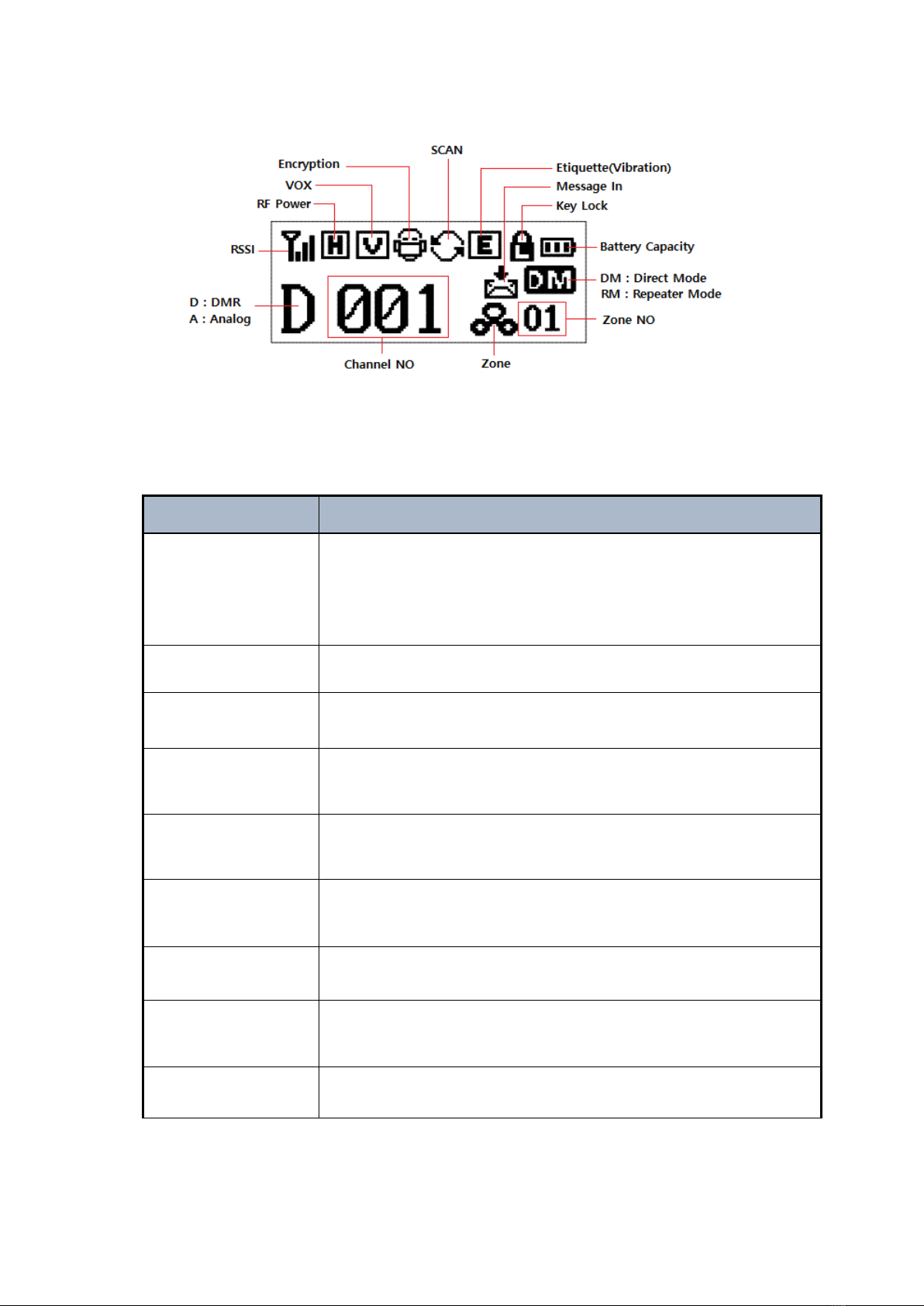
OLED LCD Display
DC+7.4V Li-ion / 2,600mAH High capacity battery

3
2. Specification
2.1 DX-5000 Series
General
Frequency Range
Frequency Stability
Channels
Programmable Channels
Channel Spacing
Digital Vocoder
Dimensions
Weight
Power Source
Current Drain (Maximum)
DX-5100 : 136~174 MHz
DX-5200 : 216~224 MHz
DX-5400 : 400 ~512 MHz
±1.5ppm (-30 to +60℃)
1,024 channels
64 (1 Zone = Max 1,024 Channels)
12.5KHz
AMBE++
113mm(H) x 54.5mm(W) x 35.5mm(D)
280g
DC +7.4V Li-ion 2,600mAH Battery
Receiving mode –420mA (Maximum Audio)
Transmitting mode –1,200mA
Standby mode –110mA
Receiver
Sensitivity
Selectivity
Spurious and Harmonic Rejection
FM Hum and Noise Ratio
Audio Output Power
Audio Distortion
Audio Response
Input Impedance
Antenna
0.25uV (BER 1%)
60 dB (12.5KHz)
36 dBm (<1GHz) -30dBm (>1GHz)
40dB (12.5KHz)
1 Watt / 16 ohm load
Less than 3% at rated output
+1, -3 dB from 6dB per octave de-emphasis Characteristic from 300 ~ 3000Hz
50 ohms
External Antenna, 0.0 dBi
Transmitter
RF Power Output
Spurious and Harmonic
FM Hum and Noise Ratio
Audio Distortion
Audio Frequency Response
Output Impedance
5/1Watt
-36 dBm (<1GHz) -30dBm (>1GHz)
40dB (12.5KHz)
Less than 3%
+1, -3dB from 6dB per octave pre-emphasis Characteristic from 300 ~ 3000Hz
50ohms

4
3. DX-5000 series accessories
* The accessory parts may be changed at the request of the buyer
Device Battery 2 slots charger
Belt Clip (Holster) Antenna User manual
Figure 3-1) DX-5000 series main accessories
XB-2600 : 2,600mAH Li-ion Battery Pack
XC-100D : 1 slot charger
XC-200D : 2 slots charger
423D-WS : 400~450MHz SMA Whip antenna
460D-WS : 440~470MHz SMA Whip antenna

5
3.1 Appearance of DX-5000 Series
Figure 3-2) DX-5000 series appearance

6
Figure 3-3) LCD descriptions & Icons
3.2 Basic Operation
Buttons
Operation Description
Power On/Off
Volume switch(Knob)
Turn the volume switch (Knob) clockwise or counterclockwise to power
On/Off
To increase/decrease the volume, turn the volume knob with power on,
then, Speaker icon indicates volume increase/decrease
PTT
Press PTT button to transmit
Zone button
The registered zone is selectable in order. On the selected zone, use ▲/▼
buttons to move up and down the list.
RF output,
High/Low button
Press once to make high output
Press again to make low output
Menu/OK button
Press MENU button to enter Menu
Press MENU button to see the current menu state
Menu / Channel
Up/down button
Press MENU button and press ▲/▼to move up/down the MENU list.
Press ▲/▼to change channel
Cancel/Return button
Press Cancel/Return button to exit out from the menu
Contact List button
Press the button to enter the contact list directly. Press the ▲/▼to move
through the list of contacts
Menu Exit
Press the button to exit the current menu and go back to the menu list

7
4. Basic Operation
Please read the instruction manual thoroughly before using the product.
This manual provides useful information in regards to the basic operation of the radio.
4.1 Antenna installation and Removal
To install the antenna, insert the antenna into antenna connector and screw the antenna
clockwise. To remove the antenna, screw the antenna counter clockwise.
Figure 4-1) How to tighten and loosen the antenna from the radio
1. Overtightening the antenna as it may cause damage to the Radio.
2. NEVER HOLD by the antenna when carrying the device.
3. Transmitting without an antenna may damage the Radio.
4.2 Battery installation and Removal
As shown the figure 4-2, to put the battery, align the battery pack with the groove of the
device and press the device into the direction of the arrow #2. To remove the battery, push the
battery locker and pull the battery out of the device to the direction of the arrow # 3.

8
Figure 4-2) How to install and remove the battery
4.3 Belt Clip Installation and Removal
1) Installation belt clip: To attach the belt clip, align the belt clip to the grooves on the back of
the radio as shown and push it down to the direction number 1. Clip will “click” when locked.
2) Removal belt clip: To remove the belt clip, push the locking tab to the direction number 2
and pull the belt clip up to the direction number 3 at the same time.
Figure 4-3) How to install and remove the belt clip

9
4.4 External Accessory Connector Jack
The accessory connector is used to connect an external headset or SW programming.
Open the accessory cover and align the accessory connector with the accessory jack. Push the
connector into the jack to attach and pull it out to remove. Keep cover closed when not using
accessories.
Figure 4-4) External accessory connector jack
4.5 How to charge the battery
Please charge the battery before using the radio for best performance and safety. When you
think that the performance of the radio has degradation, please charge the Radio and Battery
as described below.
1) Turn off the Radio first and plug the Radio in the charger (XC-200D), then RED light
turns on during charging.
2) When charging is completed, green light turns on to terminate.
3) Two slots allows you to charge the Radio and Battery at the same time
4) The charger (XC-200D) will prioritize the Radio charging than battery charging.

10
Figure 4-5) How to charge the Radio and battery
5. Operating Instruction of DX-5000 Series
DX-5000 series body buttons are defined as shown the figure 5-1.

11
Figure 5-1) Parts & Buttons
5.1 Power ON/OFF Volume Switch (knob)
Turn the power on/off switch clockwise to power on, then LCD display screen will start with a
sound to make a beginning. Turn the power on/off switch counter-clockwise to power off, then
LCD display screen will end with a voice guide “Good-bye”.
And also audio volume level can be adjusted by turning the power on/off volume switch
clockwise/counter-clockwise.
5.2 PTT Button
Press the PTT button to transmit voice and release the PTT button to receive voice. It is
recommended to talk putting 2~4 inches distance from the microphone.

12
5.3 ZONE Button
Press zone button to search the ZONEs programmed via CPS program and press the ▲/▼
buttons to select your desired zone.
5.4 Menu Button
To enter the menu tree as displayed in Figure 5-2, press the MENU button. Press the ▲to move to the
right and press ▼to move to the left. To enter the submenu, press the MENU button one more time.
Figure 5-2) DX-5000 Series Menu
Figure 5-3) DX-5000 series Menu Tree
5.5 Menu ▲/▼Button and Channel ▲/▼Button
Press the MENU button to enter. Press ▲/▼button to choose from the menu list. And Press

13
▲/▼button to move UP / Down the channel.
5.6 Contact Button
Press the Contact button to enter the contact list such as Individual call, Group call, All call
programmed into the Radio.
5.7 Menu Exit Button
Press the Menu Exit button to exit out.
5.8 Accessory Jack
The accessory connector (Jack) is used to connect an external speaker microphone, headset or
any external device. And also, it is used for CPS programming and upgrading new firmware.
5.9 LED Display
LED indicates the operational status of the radio.
①LED will illuminate RED color when transmitting
②LED will illuminate GREEN color when receiving
③If the LED blinks GREEN, the frequency is the same but the color code does not match
④Low Battery: LED blinks RED with beep sound
6. How to charge the battery
6.1 Precautions
1) The DX-5000 series uses a large-capacity 2,600mAH Li-ion battery (XB-2600). Use the
original battery and original charger to ensure you are using safe and reliable equipment

14
and to extend battery life.
Using a charger or battery brand other than XRadio can cause battery or
radio damage.
2) Please use a fully charged battery before using the radio for best performance and safety.
3) Turn off the radio before charging the battery.
Continuous rapid discharge (when the positive or negative terminal of
the battery touches the metal object) will cause a fatal defect to the
battery and may cause explosion or fire.
6.2 When to charge the Battery
When your radio has low battery power, the communication distance becomes shorter and the
performance of the radio can be degraded. These are the radio’s indicators to alert you a low
battery:
1) When you feel the battery consumed a lot.
2) When the red LED blinks during transmitting or receiving in every 5 seconds.
3) When battery indicator icon and red LED blink.
4) A beep sound alerts low battery.
6.3 How to charge the battery
1) Plug the adapter of the XC-200D charger into the AC220V power outlet.
2) Turn off the power completely before charging and insert the Radio into the charging
port.
3) Although charging is completed with Green LED, keep charging more than 30 minutes
for fully charged battery.
Status
LED Indication
Status
LED Indication
Charging
Red LED lights
Error Detection
Red LED blinks
Charging
complete
Green LED lights
Keep Charging
Green LED lights
7. DX-5000 series radio operation
7.1 Menu functions
To enter the menu tree, press menu button. There are 8 main menus in menu mode. The user
can use the radio more conveniently if the user set it according to usage purpose and
environment.

15
Figure 7-1) DX-5000 series main menus
☞Note) If the menu is not operated for at least 25 seconds after launch, the radio will revert
to standby mode.
7.1.1 Contact
The Contact List provides a list of individuals, groups or all calls of which you can make a direct
call. To initiate a call, select the Contacts section from the menu (or press the contact button
for direct access), press the menu/enter button to see the list of contacts, press ▲/▼buttons
to the desired contact and press the PTT button to initiate the call. The lists of contacts can be
set within the radio by the CPS program.
ICONs shown in contact list
- : Individual contact list (individual calls, individual messages can be sent)
- : Group contact list (group call, group message can be sent)
- : All contact lists (terminals with the same channel and color code are usable)
7.1.2 Text Messages
If you are in another mode or miss the message, the message icon will be displayed
indicating a new message has arrived. The Message selection offers the ability to perform
one of three functions: Quick Message, Inbox, and Outbox.
1) Quick Text Message
The ability to send from a choice of 10 preset messages with up to 40 characters per text
message. The preset messages can be set by the CPS program. Select Quick Text from the
message menu by pressing the menu/enter button to view the registered message(s). Using
the keys, select the message you want to send, and press the menu/enter button to see the
contents of the message. Press the menu/enter button again to view the list of contacts, and
using the keys, select the contact for the message to be sent. Press the menu/enter button
and the message will be sent to the contact(s).
2) Inbox.

16
Inbox stores up to 10 received text messages; when the received messages exceed 10, the
oldest message is cleared and the newest incoming message is registered. When a new
message arrives, the contents will be displayed on the LCD screen. When you choose messages
stored in the list, you can view the received messages and the caller ID that initiated the call. If
you want to delete text message from the inbox, select “delete all” from within the inbox menu
and press the menu button to delete all messages.
3) Outbox.
Outbox stores up to 10 outgoing text messages; when the outgoing messages exceed 10, the
oldest message is cleared and the newest sent message is registered. When you choose
messages stored in the list, you can view the sent messages and the caller ID to whom they
were sent.
If you want to delete text message from the Outbox, select “delete all” from within the outbox
menu and press the menu button to delete all messages.
7.1.3 Call Logs
This function allows the viewing of incoming and outgoing calls from individuals only. Any
group call, all calls are not saved. The contents are managed in the same manner as in the
inbox and outbox of the text message.
1) Inbox
Inbox stores up to 10 received calls; when the received calls exceed 10, the oldest call is
cleared and the newest incoming call is registered. When a new call incomes, the caller
ID will be displayed on the LCD screen. If you want to delete caller ID from the inbox,
select “delete all” from within the inbox menu and press the menu button to delete all
IDs.
2) Outbox
Outbox stores up to 10 outgoing calls; when the outgoing calls exceed 10, the oldest call
is cleared and the newest outgoing call is registered. When a new call made, the caller ID
will be displayed on the LCD screen. If you want to delete caller ID from the Outbox,
select “delete all” from within the outbox menu and press the menu button to delete all
IDs.
7.1.4 Call Recording
This function is used to record the content of outgoing and incoming calls.

17
Settings, Lists and Delete all functions are available. Up to 63 conversations/recordings can
be stored with each recording limited to 2minutes and 30 seconds. If you want to delete
recordings, select “delete all” from the Voice Recording menu by pressing the menu button.
When the encryption mode is selected, only encrypted call can be
recorded, and non-encrypted call cannot be recorded.
7.1.5 Scan
This function provides the ability to turn scan on/off and to review the scan list as programmed
into the radio via the CPS program. During the scan, set the channel on you desire to listen,
and receive signal. If you want to make a call while scanning, set it via the CPS program.
1) Scan ON/OFF
On/Off setting can be set in the Scan Menu
2) Scan list
The scan lists can be set on the CPS program.
7.1.6 ZONE
Up to 64 zones (with up to 1,024 channels per zone) can be programmed into the radio via the
CPS program. To select the desired zone, press the ▲/▼buttons and press the menu/enter
button to accept the zone.
7.1.7 Setting
This function allows the change to the settings of Power Level, Voice Encryption, Voice
Operated Transmit (VOX). Lone Worker, Busy Channel Lock (BCL)/Busy Channel Lock Out
(BCLO), Button (Keypad) Lock, Tones, LCD Backlight, LCD Brightness, LED Control, Language.
1) Power Level
This function sets the power transmitting level at high or low. The setting of low power
improves battery life, but can diminish talk range.
2) Voice Encryption (Digital Mode Only)

18
This is a feature to encrypt the incoming and outgoing voice. Voice Encryption function
for each channel can be set through CPS in Digital mode. Total number of available voice
encryption is from 0 to 65535 and its code can be set via CPS program.
3) VOX
This function allows transmitting without using the PTT button.
VOX sensitivity level can be adjusted from 1~5 with 5 being the most sensitive and the
sensitivity can be set via the CPS program.
4) Lone walker
This function can inform others about your safety within the time set in the menu. Set-up
time is from 1 to 100 minutes.
5) BCL/BCLO (Busy Channel Lockout / Busy Channel Lockout Override)
This function prevents interference when the current channel is busy.
BCL (Busy Channel Lockout): Transmission is prohibited when the current channel is busy.
BCLO (Busy Channel Lock Override): Transmission is allowed regardless of busy channel.
6) Keypad (Button) Lock
This function locks the button to prohibit the accidental press of keys and buttons.
When the keypad lock is set, all keys/buttons are locked except the PTT button, the
emergency button, and power ON/OFF button. If any of these buttons are pushed, the
keypad lock will enable again after 25 seconds from the pressing of the last button.
Press the P1 button for 2 seconds to temporarily unlock.
7) Tones
This function enables or disables the tones.
Additional tone settings can be set via CPS program.
8) LCD BACKLIGHT
This function enables or disables the LCD backlight ON/OFF.
9) LCD Brightness
The function is to adjust the contrast/brightness of the LCD from 1 to 7 levels.

19
10) LED Control.
The function is to set the enable or disable the LED status display. It can be set via the CPS
program.
11. Language
The function is to select the language for the menus.
7.1.8 Radio information
A menu that shows the information of the device.

20
8. Precautions
8.1 Matters affecting the performance of the equipment.
Don’t remove the antenna from the radio and don’t modify the antenna or make
any changes to the antenna. Strong electronic waves emitted from the radio
can have an effect on the performance of the radio if the antenna is modified
and can cause the radio to have a defect not covered under warranty.
Don’t use other manufacturer’s accessories (such as rechargeable batteries,
adapters, external speaker microphone and earphone, etc.). Unknown or
unauthorized accessories may damage the radio and void the warranty.
Don’t disassemble or reorganize the radio. The disassembly or reorganization
of your radio is punishable by law and can cause damage to the radio that will
not be covered by the warranty.
Don’t use frequencies you do not have a permit for. Unauthorized frequencies
is punishable by law.
Avoid excessive shock to the radio.
Don’t place the radio where the direct sunlight, humidity and/or the high
temperature occurs, battery damage can occur in this environment.
Don’t place the Radio or Battery in vehicle. This may explode in the summer
temperature.
Do not disassemble or damage the battery pack.
8.2 Influences to the operations of Radio or other Equipment.
The Radio emits a strong electronic wave which may have an effect on the operation of other
equipment and can also be affected by those other devices.
Please turn off the radio before boarding an airplane. If you want to use the
radio in the airplane, please follow the airplane and crew rules & instructions.
If using radio in an area where medical equipment is being used, please get
permission from relevant staff to prevent interference issues.
Be careful when using your radio in a place where computers or other
electronic devices are being used because the strong electronic waves from
the radio can affect this equipment.
This manual suits for next models
3
Table of contents
Other XRadio Transceiver manuals