XRPlus XRS 2004 Series User manual

USER’S MANUAL
(XRS 2004 Series)
Stand Alone Type
DVR SYSTEM
XRPLUS Incorporated

•INDEX
• CHAPTER 1. Specification & System organization
1. Specification -------------------------------------------------------------- 4
2. Product Contents List -------------------------------------------------------- 6
3. System Organization --------------------------------------------------------- 7
•CHAPTER 2. Description
1. Front Panel --------------------------------------------------------------- 8
2. Rear Panel --------------------------------------------------------------- 10
3. Remote Controller ---------------------------------------------------------- 11
• CHAPTER 3. Installation
1. Hard Disk Installation ------------------------------------------------------- 12
2. CD-RW & Hard Disk Installation ----------------------------------------------- 14
3. Camera Connection -------------------------------------------------------- 16
4. Monitor Connection -------------------------------------------------------- 16
5. Computer Connection ------------------------------------------------------- 16
6. Network Connection -------------------------------------------------------- 16
7. Alarm/Relay/PTZ Connection ------------------------------------------------- 17
8. Power Connection --------------------------------------------------------- 17
9. Finishing Installation -------------------------------------------------------- 18
※ Hard Disk Format ---------------------------------------------------------- 18
•CHAPTER 4. Display
1. System Power ON ---------------------------------------------------------- 19
2. Screen View Selection ------------------------------------------------------ 20
3. Screen Rotation Mode (SCR MODE) -------------------------------------------- 20
4. PTZ/FOCUS Control -------------------------------------------------------- 21
5. System Power OFF --------------------------------------------------------- 21
•CHAPTER 5. Search
⊙ Go to Search Mode --------------------------------------------------------- 22
1. Search by Date/Time ------------------------------------------------------- 22
2. Search by Event ----------------------------------------------------------- 23

•INDEX
• CHAPTER 6. MENU
⊙ Go to Menu -------------------------------------------------------------- 25
⊙ Go to System Setup -------------------------------------------------------- 25
1. Display ------------------------------------------------------------------ 26
2. Camera ----------------------------------------------------------------- 27
3. Audio ------------------------------------------------------------------- 30
4. System ------------------------------------------------------------------ 30
5. Event/Sensor ------------------------------------------------------------- 36
6. Disk Management ---------------------------------------------------------- 39
⊙ Go to Record Menu -------------------------------------------------------- 40
1. Recording Operation -------------------------------------------------------- 40
2. Continuous/Motion Record Schedule -------------------------------------------- 41
3. Alarm Record Schedule ----------------------------------------------------- 42
⊙ Go to Archiving ----------------------------------------------------------- 43
1. CD-RW and USB Back up --------------------------------------------------- 43
• CHAPTER 7. CLIENT
⊙ Remote Program Install ----------------------------------------------------- 44
1. Function Introduction ------------------------------------------------------- 46
2. Setting ------------------------------------------------------------------ 47
3. Monitoring --------------------------------------------------------------- 54
4. Search ------------------------------------------------------------------ 58
5. Web Client --------------------------------------------------------------- 65

4
1. Specification
Video standard PAL/NTSC
Audio 2-way Audio conference
Monitor display Real time:25 Fps (PAL), 30Fps(NTSC) per camera
Covert camera operation Programmable
Event/Log search Up to 1,000,000 for user login/out, config changes, remote access,
connects/disconnects
Record Scheduling Daily, Weekly adjust specific Hr per channel
Remote Access TCP/IP, View, Search, Recording & Control by Client Program or I.E.
Playback Single and quad picture
Pre/Post alarm recording 5 secs(Pre), 3 mins(Post), programmable per camera
VGA For monitors with Multi Sync Function only(1024 X 768(60Hz))
Activity detection 12x12 grid, Sensitivity levels: 10
Back-up file formats AVI, JPG, BMP
Simplex/Duplex operation Triplex
Video inputs 4 x 1Vp-p, CVBS, 75ohms, BNC, looping inputs
Monitor outputs 1 x CVBS/S-VHS, VGA
Spot output 1 x 1Vp-p, CVBS, 75ohms, BNC
Audio inputs 4 x line-in, RCA sockets
Audio output 1 x line-out, RCA socket
Resolution 352x240,704x240,704x480(NTSC), 352x288,704x288,704x576(PAL)
Compression standard Mpeg4
Recording speed 352x240 : 120/100 (NTSC/PAL) , 704x240 : 60/50 (NTSC/PAL)
704x480 : 30/25 (NTSC/PAL)
Image size 3-5 Kbyte (352x240, 352x288), 5-10 Kbyte (704x240, 704x288)
6-16 Kbyte (704x480, 704x576)
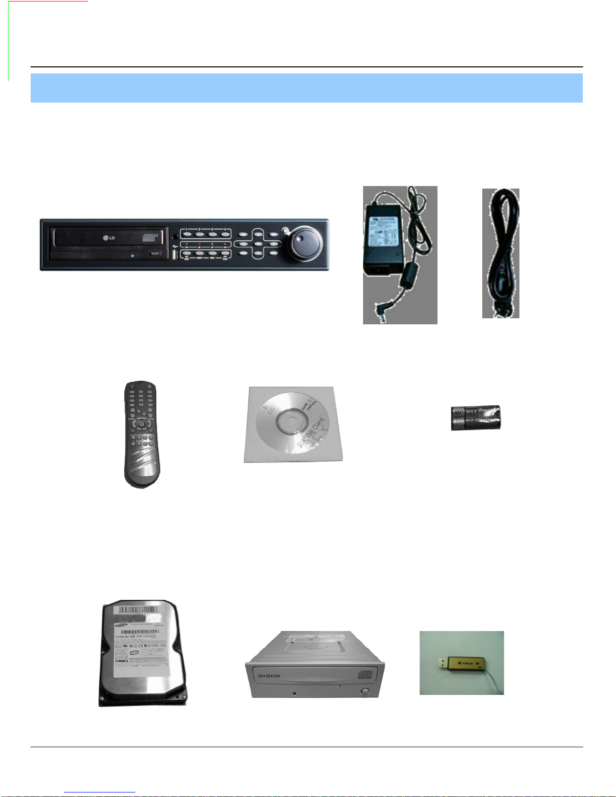
Hard disk capacity 2 X HDD, 1 X CD-RW (STANDARD DC SUPPLY USE)
Secondary Storage USB default (USB memory stick, USB HDD), CD-RW
Alarm inputs 4 x TTL, programmable as NC/NO
Alarm outputs 1 x Relay with NO/NC contact; 30VDC/1A, 125VAC/0.5A resistive
1. Specification & Organization

5
Network Speed Control 8 levels
Power consumption Approx. 60watts
Temperature range 5℃to 50℃
Pre-alarm recording Up to 5 sec., programmable per camera
OSD languages English, Spanish, Chinese, Dutch, Portuguese, French, Russian, Japanese,
Polish, Romanian, German
Ethernet interface 10/100-Base-TX, RJ-45
Remote Function Live View, Live Recording, Search, Set-up, Back-up
PTZ Control RS-485 interface
Supply voltage 100VAC-240VAC, 5A, 60/50Hz
1. Specification & Organization

6
2. Product contents List
Please Confirm the Contents When open Package.
①Basic Contents
Remote Controller
Remote Client
Program Install CD /
user manual
AAA Battery X 2
12V Adaptor Power Cable
② Option Contents
HDD CD-RW USB MOMORY
XRS 2004
1. Specification & Organization

7
3. System Organization
NETWORK
Camera #1-4
Alarm Sensor #1-4 Remote Client PC
XRS 2004
Video In
Video Out
Relay Out
VCR VGA
Monitor AV Monitor
Image Printer
TCP/IP
Alarm Input/Out
Remote
Controller
CD-RW
(It is not supported)
Backup
AVI Backup
WEB Client
USB
1. Specification & Organization

8
① Power : System Power On/Off.
② Remote Controller Sensor Input.
③ CD-RW : CD-RW Device for Backup.
④ USB Port: USB port for use the USB memory stick and USB HDD Backup
⑤ Led Indicator : Indicate Present System Status Information.
( POWER: System On/Off , RECORD: Record On/Off , NETWORK: Client Network Connection
Status, ALARM: Alarm Sensor Detection Status )
⑥ Channel Selection Button : Select Channel or Input Password.
⑦ SCR MODE : Select Screen Division Mode or Rotation Mode.
⑧ SEARCH : Go to Search Mode for Searching Data.
⑨ MENU : Go to System Menu.
⑩ PTZ/FOCUS : Go to Camera PTZ/FOCUS Control.
⑪ Search Controller : Searching Recorded Data or Control Menu & PTZ/FOCUS.
⑫ ENTER : Apply Changing Setup.
⑬ RETURN : Cancel Setup or Return to Previous Mode.
⑭ JOG SUTTLE : Search Mode for Searching Data
1. Front Panel (XRS 2004)
• Power Button is Soft Style to Prevent System Failure by Wrong Operation.
• Channel Selection Button is Prior to SCR Mode.
• When Remote Controller Sensor Input is Blocked by Something, it Cause
1Remote Controller do NOT Work Properly.
• When Press any Button, it Operate with Beep Sound.
•In Case of CD-RW, the Real Appearance will be Differ from the above Picture
1Depends on its Model.
2. Description
Tip
①②③
④⑤
⑥
⑦⑧⑨⑩
⑪
⑫⑬
⑭

9
① Video In : BNC Port for Connection of DVR & Camera. (4 Camera Connectable)
② Loop Back : Output DVR Camera Video to Loop Back Port. (4 BNC Port)
③ Monitor Out : Output DVR Video to AV Monitor.
④ Spot Out : Output Spot-out Video to AV Monitor.
⑤ NTSC/PAL : Select NTSC or PAL Type.
⑥ VGA OUT : Output Video to a Computer Monitor by Connected VGA (Option)
⑦ SVHS : Output Video by Connected SVHS.
⑧ Audio Out : Output Audio Data.
⑨ Audio In : Audio Input Terminal Related with #1~4 Camera.
⑩ Ethernet (TCP/IP) : Port for Cross cable. (Possible to Remote Surveillance.)
⑪ Alarm/Relay/RS-485 : Connect Port for Sensor, Relay, & PTZ.
⑫ RS-232C : Connect Port for Program Debug.
⑬ DC Power Input : Power Supply by DC 12V Adaptor.
• When System Installation, Please Install under System Power OffStatus.
• Please Use Specific Adaptor when Power Supply.
2. Rear Panel
2. Description
Tip
①③
④⑤
⑥⑨
⑧⑩
⑪
⑬② ⑦⑫

10
POWER
System
ON/OFF
MENU: Open Menu
RETURN
Cancel Setup
or Return to
Previous
ENTER: Apply Setup Change
Channel Selection Button
(4ch Available, #1~4 Button)
Change
Screen Mode
Open
Search Mode
PTZ/IRIS Mode
• Unused Button’s Description is Omitted.
• Every Button is Operated Same as Front Panel Button.
• Remote Controller can Operate when Remote Controller Sensor Input Part Reacted Each Other.
※ If there are many DVR at the same place, they are reacted together when press remote controller.
Search Controller : Control Playback Option,
Menu Movement, PTZ/Focus Control
3. Remote Controller
2. Description

• Jumper Setup as master or Slave, Following the
`Direction of Surface of Hard Disk.
• Jumper Located at Hard Disk Data Cable or
1Rear Side of Hard Disk.
• If One Hard Disk Installation, Setup as Master
If Two Hard Disk Installation, Second One Setup as Slave.
① Jumper Setup as Master or Slave
11
1. Hard Disk Installation
※ Example of Samsung HDD Jumper Setup
• Refer to General Pin Setting in Jumper Pin Setting on HDD Surface.
• When One HDD Install, Setup Pin as Master and Connect Pin
1at the Left End of Jumper.
• When Two HDD Install or Additional Install, First One Setup as
1Master and the Other is for Slave. Slave Setup has No Pin.
• When More than Two HDD install, Setup as Master or Slave
1to Connect One IDE Cable at the Same Method of Above.
!!Please Use Hard Disk which Possible to Supply Higher than
UDMA66.!!
‼ When Hard Disk Add or Exchange, Must System Off
Properly (System Off by Power Button). If not, it’s a
Cause of Fatal Hard Disk Error.‼
② IDE Cable Connection to Main Board
• Confirm the IDE Cable Inside of Product
• Among the Three Connector, Indicated Blue Color
1Connector Must be Connected with Main Board.
Other 1Connectors Connected with HDD
3. Installation

12
② Connect IDE Cable to Hard Disk
• Insert Disk, Red Cable Head to Power Cable Plug
• Connect Power Cable to Hard Disk in the Same Way
※ If One HDD Install, Connect with End of Connector (Black)
Recommended.
If Add HDD, Connect with Middle Connector (Gray)
Recommended.
One HDD Installation Two HDD Installation Bracket Installation
③ After Finishing Cable Connection, Attach Hard Disk with Screw & Bracket
• IDE Hard Disk can connect two equipment at one
cable (port). For the purpose of prevent confusing,
two equipment named ‘Master’ & ‘Slave’. ’Master’
is one hard disk or first hard disk and ‘Slave’ is
below second hard disk.
ㅡMaster, Slave?
Tip IDE2 IDE1
For Rear Panel
• When Install Master HDD, Please Connect
1at IDE1 Port by Master Cable.
• It means, Master Connector which
1Connected with IDE1 Cable Must
1Connected with HDD (Master).
3. Installation

• Jumper Setup as Master or Slave (Refer to CD-RW
1Direction at the Surface).
• If Install One CD-RW at One IDE Cable, Setup as Master
If Install One CD-RW & HDD at One IDE Cable,
1CD-RW Setup as Slave.
① Jumper Setup as Master or Slave
13
1. CD-RW & Hard Disk Installation (XRS 2004)
‼ When CD-RW Install, Exchange, or Remove, Please
System Off Properly (System Off by Power Button) and
Disconnect DVR Power.‼
Incase of LG-8526B, MASTER
② Remove Bracket for W/O CD-RW at the Front
③ After Assemble with Bracket, Attach to the Case
3. Installation

14
⑤ After Assemble with HDD Bracket & Connect Cable (Refer to Previous page for HDD Setup)
⑥ Example of Install CD RW & HDD
④ Connect by IDE Cable & Power Cable at the CD-RW
<EX>When Two HDD Installation
HDDx1 HDDx2 HDDx2 + CD-RW
Tip
• When Install Master HDD, Please Connect
1at IDE1 Port by Master Cable.
• It means, Master Connector which
1Connected with IDE1 Cable Must
1Connected with HDD (Master).
IDE2 IDE1
For Rear Panel
3. Installation

15
2. Camera Connection
Connect Camera at BNC Port in Back Side Panel.
3. Monitor Connection
Connect Monitor Terminal or S-VHS Terminal to Monitor
4. Computer Connection
Connect VGA OUT Terminal to Computer Monitor
5. Network Connection
Connect Ethernet Terminal and Network Cable
3. Installation

16
Example of Connection PTZ Camera No. 14 Pin Connector
6. Alarm/Relay/PTZ Connection
①ALARM
Alarm Input - ‘IN1, IN2, IN3, IN4’: Connect Sensor Input by Channel
‘GND’: Connect Ground System
②RELAY
Alarm Output – ‘NO, NC’ : After Checking Alarm Output Type (Normal Open or Normal Close)
and Connect to ‘NO, NC’
‘COM’ : Connect Remain Grounding Conductor
③ RS-485
Connect PTZ Camera – ‘D+, D-’ : Connect PTZ Camera Control Line (+ , – Terminal)
PTZ 14 Pin Cable
⑨R+
⑩R-
⑪T+
⑫T-
RS485
D+
D-
7. Power Connection
Connect DC Power Input Terminal and Specific Adaptor
3. Installation
①②③

17
8. Finishing Installation
System Start by Power Button after Finishing Installation
※ Hard Disk Format
- If Do Not New Hard Disk Format, System Can’t Recognize the HDD.
So it’s Same Situation of No HDD. Please Format HDD when Insert New HDD.
(Only Display Possible, Not Work Menu & Search)
1. Power On 2. New HDD Format
(Select By Play , Backward Play Key)
When new discovery HDDs are two, It ask about each
format. Then choose the Yes about all HDDs. If you
Format the first HDD only, maybe second HDD don’t
Format.
※ When you are doing to format, Never turn off.
If tuen off, HDD is able to occur fatal error.
3. System Start (Initial Mode)
3. Installation

4. Menu
1.Display
- Video Setup for Watch Mode
• Status Bar : Record Condition Mark On/Off
(Recording: Red, Pre-recording : Green)
• Camera Title: Setup Camera Name to Show Left-Upper Side
• Event Icon: Indicate the menu location by icon
• Border : Border Mark On/Off when 4CH Division Watch Mode
• Border Color : Select Border Color
(White, Blue, Red, Yellow, Green, Gray)
• Motion Sensor : Set Up Motion Sensor
• Alpha Blending: Choose the transparency(1~100)
•GUI Blending
• Sequence Dwell : Setup Rotation Cycle Time
(1~60 Sec.) when 4CH Rotation Mode at Watch Mode
• Spot-Out Dwell : Setup Spot-Out Time Cycle
(1~60 Sec.) to Transmit Video
• De-interlace Mode : Remove Screen Spread on High
Resolution , Low Frame ※Only Applying When D1(704X480)
• Alarm Pop-Up Mode: When alarm happen, Alarm happened
channel Pop-up
• Alarm Pop-Up Dwell: Alarm Pop-up Time(1~60Sec.)
•ENTER
RETURN
•
To Open Detail Menu, press “the Enter”
Return to Previous Menu or Return to Watch Mode
1-1. OSD
• Every System Setup can Change or Maintain
1at Menu (6 Setup)
•Move to Menu Using by Up
& Down Button
1-2. MONITOR
Tip • When finishing that change the setup data,
Press the certainly.
12

4. Menu
• Activation : Activation On/Off
• List : Sequence Title
1-2. SEQUENCE
• Choose Add to Add Sequence
• Input Sequence Title
• Choose Activation
• Save and Exit
• When input sequence title, You can use virtual
keyboard by pressing enter button.
13

2.Camera
-Setup Camera
2-1. Camera Title
4. Menu
• Covert : Setup Covert On/Off
*What’s Covert?
When Covert On Watch Mode, Display Video is Hidden, but Recording is On.
• Title : Setup Camera Name by Virtual keyboard
• Control the Monitor Bright, Contrast, Color, Tint
• All Setup Possible to Control 0~100
• Setup Channel by Channel
2-2. Color Setup
• Input the title by “Enter” after choose by
button.
14
Table of contents
Other XRPlus DVR manuals