Xsens DOT User manual

1
www.xsens.com
Xsens DOT
User Manual
Document XD0502P, Revision C, 17 August 2020

2
www.xsens.com
Revision
Date
By
Changes
A
7 Jan 2020
XUF
Initial release
B
25 April 2020
XUF
Add charger spec and attachment method
Add magnetic distortion description
Add cleaning and storage method
Update firmware update operations
Add sensor components specifications
Add coordinate systems
Add heading reset function
Update data outputs information
C
17 August 2020
XUF
Add sync and recording LED
Update software package
Add multiple sensor connection tips
Update state transition diagram
Add synchronization feature
Add recording function
Add firmware compatibility
Update Xsens DOT specifications
© 2005-2020, Xsens Technologies B.V. All rights reserved. Information in this document is subject to change
without notice. Xsens, MVN, MotionGrid, MTi, MTi-G, MTx, MTw, Awinda, Xsens DOT and KiC are registered
trademarks or trademarks of Xsens Technologies B.V. and/or its parent, subsidiaries and/or affiliates in The
Netherlands, the USA and/or other countries. All other trademarks are the property of their respective owners.

3
www.xsens.com
Table of Contents
List of references ...........................................................................5
1Introduction.............................................................................. 6
2Getting Started ......................................................................... 7
2.1 Starter set................................................................................................. 7
2.2 Hardware .................................................................................................. 7
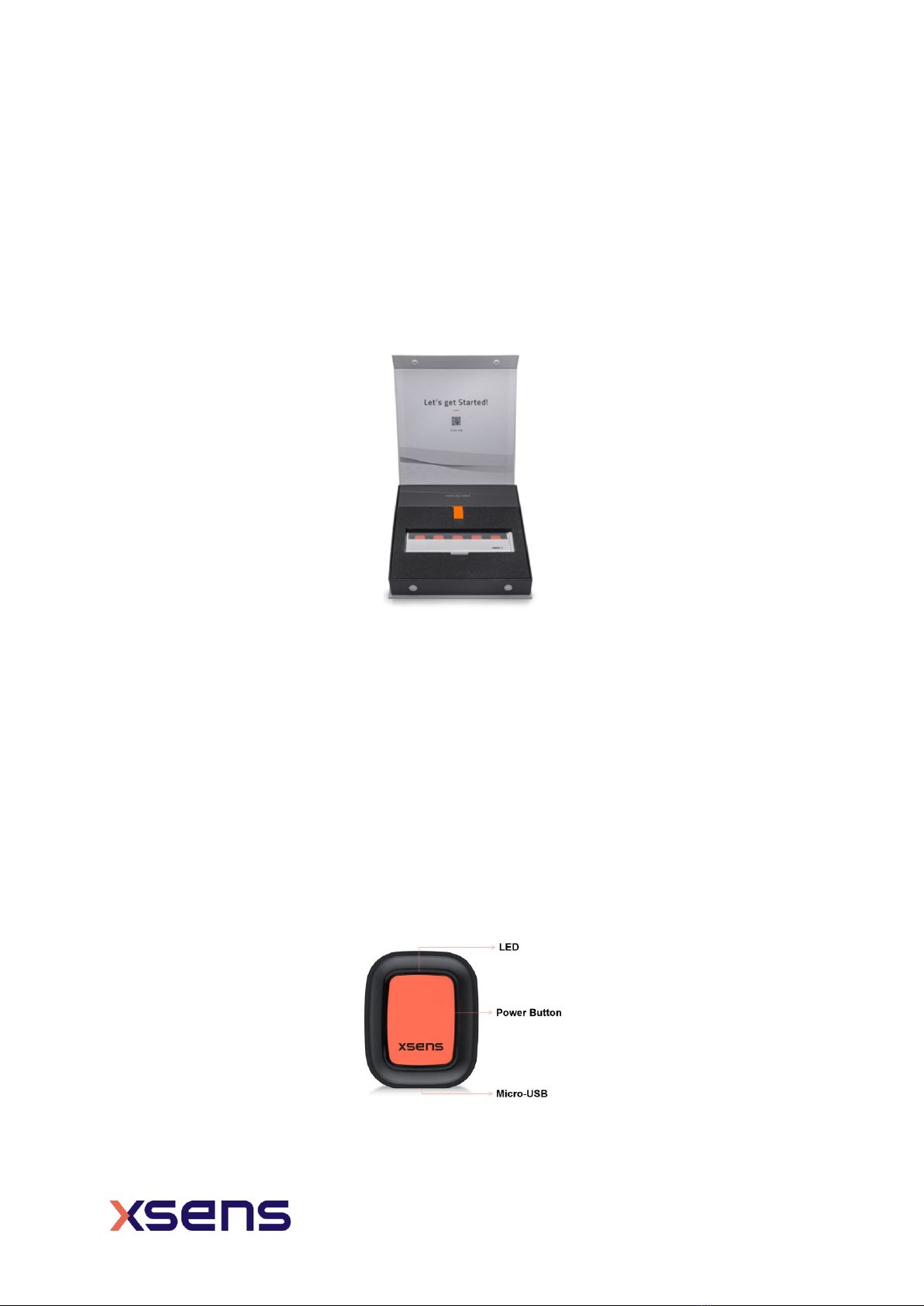
2.2.1 Xsens DOT ........................................................................................... 7
2.2.2 LED status ........................................................................................... 8
2.2.3 Charger ............................................................................................... 8
2.2.4 Body straps and accessories................................................................... 9
2.3 Software ................................................................................................... 9
2.3.1 Supported platforms ............................................................................. 9
2.3.2 Choose your software...........................................................................10
2.4 Tips for best practice .................................................................................10
2.4.1 Multiple sensors connection...................................................................10
2.4.2 Magnetic distortion...............................................................................10
2.4.3 Cleaning method..................................................................................11
2.4.4 Storage ..............................................................................................12
3Xsens DOT Overview ............................................................... 13
3.1 Strapdown integration................................................................................13
3.2 Sensor fusion algorithm .............................................................................13
3.3 Xsens DOT sensor state transition ...............................................................14
3.3.1 Power ON/OFF.....................................................................................14
3.3.2 Synchronization ...................................................................................14
3.3.3 Measurement ......................................................................................15
3.3.4 Power saving.......................................................................................16
3.4 Magnetic Field Mapper ...............................................................................17
3.5 Firmware Update.......................................................................................17
3.5.1 Firmware update..................................................................................17
3.5.2 Firmware downgrade............................................................................18
3.5.3 Firmware compatibility .........................................................................18
4Output Specifications .............................................................. 19
4.1 Coordinate systems ...................................................................................19
4.1.1 Sensor coordinate system .....................................................................19
4.1.2 Orientation coordinate system ...............................................................19
4.1.3 Heading reset......................................................................................20
4.2 Sensors data outputs .................................................................................21

4
www.xsens.com
4.2.1 Calibrated delta_q and delta_v ..............................................................21
4.2.2 Calibrated inertial data and magnetic field data .......................................21
4.2.3 Orientation..........................................................................................21
4.2.4 Free acceleration .................................................................................22
4.2.5 Timestamp and packet counter..............................................................22
4.2.6 Status ................................................................................................22
5Physical Specifications ............................................................ 23
5.1 Xsens DOT specifications ............................................................................23
5.2 Sensor components specifications................................................................23
5.3 Battery specifications .................................................................................24
6Important Notices ................................................................... 25
6.1 Warranty and Liability ................................................................................25
6.2 Customer Support .....................................................................................25
6.3 Product Compliance ...................................................................................26

5
www.xsens.com
List of references
1. Xsens DOT Quick Setup Guide [XD0501P]
2. MT Low-Level Communication Protocol Documentation [MT0101P]
3. Xsens DOT SDK Programming guide for Android [XD0201P]
4. Xsens DOT iOS SDK documentation [XD0202P]
5. Magnetic Calibration Manual [MT0202P]

6
www.xsens.com
1Introduction
Xsens DOT is a wearable sensor development platform features sensor incorporating 3D
accelerometers, gyroscopes and magnetometers to provide an accurate 3D orientation.
The embedded processor in the sensor handles sampling, calibration, strap-down
integration of inertial data and Xsens Kalman Filter core (XKFCore) algorithm for sensor
fusion. With wireless data transmission through Bluetooth 5.0, Xsens DOT can provide real-
time 3D orientation as well as calibrated 3D linear acceleration, angular velocity and (earth)
magnetic field data to a receiving device.
Xsens DOT is the start of a new Xsens product line bringing Xsens sensor solution to mobile
device platform. With simple-to-use SDK and comprehensive documentation, system
integrators can easily develop their wearable applications.
The Bluetooth Low Energy (BLE) data transmission, lightweight form factor and IP68 rating
widen the application areas of Xsens DOT, making it easy and durable to use in various
scenarios. Using different combinations of 5 sensors, it’s flexible to apply Xsens DOT to
customized measurement cases.
Fields of use:
1. Health and rehabilitation
2. Sports and exercise science
3. Ergonomics
Figure 1: Xsens DOT sensors with a charger

7
www.xsens.com
2Getting Started
2.1 Starter set
A standard Xsens DOT development kit contains:
•5 Xsens DOT sensors
•1 charger with power cable
•Xsens DOT software package
Figure 2: Xsens DOT starter kit
The easiest way to get started with Xsens DOT is to use Xsens DOT app (Android/iOS) to
connect the sensors. You can get to know the capabilities of Xsens DOT and to configure
the device according to your need. Refer to the following sections for more details about
hardware and software of Xsens DOT.
2.2 Hardware
2.2.1 Xsens DOT
Xsens DOT sensor provides 3D angular velocity using a gyroscope, 3D acceleration using
accelerometer and 3D earth magnetic field using a magnetometer. Combined with Xsens
sensor fusion algorithms, 3D orientation and free acceleration are provided. With the
wireless nature of Bluetooth 5.0, Xsens DOT sensor is an excellent measurement unit for
tracking human body motions.
Figure 3: Xsens DOT sensor

8
www.xsens.com
On top of the sensor is the LED giving the indications of sensor states. There is a power
button in the middle of the sensor to wake up, stop recording or power off sensor. The
micro-USB port at the bottom can be used to power on and charge the sensor.
2.2.2 LED status
Xsens DOT sensor has LED patterns to indicate different sensor states. Table 1 shows the
LED behaviors.
Table 1: LED patterns
State
LED Pattern
Power
ON/OFF
Powered off or power-saving mode
OFF
Sensor is being powered off
On for 1 second and fade out in 3
seconds
Measurement
Advertisement mode
Blink 1 time per second
Connection mode (not measuring)
Blink 1 time every 10 seconds
Real-time streaming mode
Blink 2 times every 10 seconds
Recording mode (including record,
export and clear data)
Fast blink 2 times and a short pause
Synchronization
OFF during sync period, all sensors
blink synchronously for 3 second if
sync succeeds.
Charging
Charging (battery full)
ON
Charging (75% <= battery < 100%)
Fade in/out, 4-second cycle
Charging (50% <= battery < 75%)
Fade in/out, 3-second cycle
Charging (25% <= battery < 50%)
Fade in/out, 2-second cycle
Charging (battery < 25%)
Fade in/out, 1-second cycle
Other states
Identifying sensor
Fast blink 8 times and a short pause
Bootloader mode (reboot the sensor can
exit this mode)
Fast blink 2 times and a long pause
MCU/battery is overheated during
charging. Charging is stopped to protect
MCU and battery
Blink 8x per second
2.2.3 Charger
The charger has a docking for 5 sensors and a cover shell, along with a USB power cable.
You can open the charger by holding the cover shell and pull out the docking from the right
side.
At the bottom of each docking slot, a micro-USB port is embedded, and a sensor can be
plugged in and out. There is another micro-USB port on the right side of the docking to
power on and charge all the sensors inside the charger. To power this micro-USB port, an
adapter of 5V/300mA is enough but we would recommend using a 5V/500mA adapter (5
sensor loads) based on standard USB 2.0 power supply.

9
www.xsens.com
Figure 4: Charger with power cable
2.2.4 Body straps and accessories
1
You can put Xsens DOT sensor inside the pocket of strap or wrapped inside the straps to
ensure good adhesion and fewer skin artefacts. Refer to this base article for more
information on how and where to attach the sensor.
2.3 Software
As Xsens DOT serves as a wearable sensor development platform, we provide all the
software needed for different demands. The software package can be download here and
includes:
•Xsens DOT Software Development Kit (Android/iOS)
•Xsens DOT App (Android/iOS)
•Xsens DOT Server
•Xsens DOT Data Exporter
•SDK Documentations (Android/iOS)
•Xsens DOT SDK Programming guide for Android
•Xsens DOT User Manual
•Xsens DOT BLE Service Specifications
2.3.1 Supported platforms
Table 2: Software supported platforms
Software
Supported platforms
SDK and APK for Android
•Android OS 8.0 and above
•ARMv8 CPU architecture
SDK and App for iOS
•iOS 9.0 and above
Xsens DOT Server
•Windows 7, 10
•MacOS
•Raspberry Pi
Xsens DOT Data Exporter
•Windows 10
Bluetooth requirements
•Best performance with BLE 5.0, DLE2supported
•Compatible with Bluetooth 4.2
1
Xsens DOT attachment solutions will be more diverse and flexible as we continue to improve
2
Data Length Extension

10
www.xsens.com
2.3.2 Choose your software
You can choose to use different software according to your demands. Please refer to the
following instructions on how to choose your software:
•If you focus on the motion data and want to quickly understand the data outputs
and capabilities of Xsens DOT, download and install Xsens DOT app. It will allow
you to:
oScan and connect the sensors
oData real-time streaming
oRecord data in sensor and export to other devices.
oFirmware update and Magnetic Field Mapper (MFM)
Refer to these base articles for detailed guidance on Android app and iOS app
operations.
•If you are a developer or system integrator who want to build your own applications,
download Xsens DOT Software Development Kit (SDK) for Android or iOS
applications. For Windows or MacOS, an open source project - Xsens DOT Server
is provided. You can download it from: https://github.com/xsens/xsens_dot_server.
•If you are familiar with Bluetooth protocol and development, and you want to build
applications on any other platforms with Bluetooth 5.0, a lower level Xsens DOT
BLE Service Specifications is provided to enable direct communication with Xsens
DOT.
2.4 Tips for best practice
2.4.1 Multiple sensors connection
Although there is no connection limit in Xsens DOT app, SDK or server, hardware and OS
constraints of the central devices have a ceiling to the maximum number of sensors that
can be connected simultaneously. Generally speaking, for Android, iOS and Windows, it is
possible to connect up to 7 sensors; in Linux PC or Raspberry Pi, it is possible to connect
up to 11 sensors. However, actual connection capability highly depends on the devices you
choose.
If big data loss or failure cases is observed during Bluetooth connection, please reduce the
Bluetooth connection number or packet size.
2.4.2 Magnetic distortion
Ferromagnetic material (iron or steel), magnets or strong currents (several amperes) in
the environment near the sensor will cause disturbance to the magnetic field. The
magnetometer in Xsens DOT sensors is used as a 3D compass to determine the direction
of the Earth true north (heading or yaw), used as an absolute reference in the calculation
of 3D orientation. For detailed information about the influence of magnetic field on
orientation, see the PhD thesis “Inertial and magnetic sensing of human movement near
ferromagnetic materials” D. Roetenberg 2006. For best results when measuring with Xsens

11
www.xsens.com
DOT, it is advised to avoid highly magnetized areas when carrying out measurements,
particularly in the beginning.
To check the magnetic distortion, you can use the Xsens DOT app to check the Magnetic
Norm
3
in magnetic field data after connecting at least one DOT. Look at the Magnetic Norm
curve while moving in the measurement area.
•Areas for which the magnetic norm = 1 and the variation remains within ±0.2 are
magnetic homogeneous and best for carrying out the measurements (see Figure
5). However, if the measurement begins with a magnetic norm of around 2 or 3,
and remains within ±0.2 of this value, the orientation should remain accurate.
•If the Mag Norm will vary depending on the location and orientation of the device
(see Figure 6), there are magnetic distortions in the environment.
Figure 5: Mag Norm fluctuates when moving Figure 6: Mag Norm is constant while moving
XKFCore algorithm running in the motion processor can compensate for the magnetic
disturbance caused by short or fast fluctuating disturbances by optimally using the
available sensor information and valid assumptions about the application. However, if the
disturbance is slow and large (>±0.2) or lasts for over 30s, it’s difficult for the algorithm
to compensate for and will influence heading accuracy.
If magnetic field norm has large fluctuations, or Xsens DOT sensor is attached to an
instrument or prosthesis that influences the magnetic field (e.g. ferromagnetic object), it
is best to carry out Magnetic Field Mapping for this DOT (see section 3.4) to recalibrates
the magnetometer.
NOTES:
•Never expose sensor to strong magnetic fields. The sensor contains the
absolute possible minimum of ferromagnetic materials. Nonetheless, some minor
components can be magnetized permanently by exposure to strong magnetic fields.
This will not damage the unit but will render the calibration of the magnetometers
useless, typically observed as a (large) deviation in the heading.
2.4.3 Cleaning method
To clean the Xsens DOT sensors and charger, use a moist cloth to wipe the surface.
3
Magnetic Norm (Mag Norm) is the norm of all magnetic axis vectors (X, Y and Z) combined. It can
be used as an indication of magnetic distortions.

12
www.xsens.com
2.4.4 Storage
If Xsens DOT sensors are not being used for a long time, please put them away half-
charged and charge the sensors occasionally to avoid battery drain. Store them in a cool
and dry place.

13
www.xsens.com
3Xsens DOT Overview
The signal processing architecture of Xsens DOT sensor is presented in Figure 7. Strap
down integration (SDI) and sensor fusion algorithm (XKFCore) are integrated into
firmware. You can get orientation increments and velocity increments from SDI, 3D
orientation and free acceleration from XKFCore. Xsens DOT sensor is factory calibrated,
making it more accurate repeatable and robust.
Figure 7: Xsens DOT signal processing architecture
3.1 Strapdown integration
Strap down integration is a method used to compute orientation and velocity increments
by integrating angular velocity from gyroscope and acceleration from the accelerometer.
The angular velocity and acceleration data are sampled and calibrated at a high frequency
(800 Hz) by the embedded MCU of Xsens DOT sensor to maintain accuracy under dynamic
movements such as running and jumping. Due to the high sampling frequency, the data
cannot be transmitted via Bluetooth directly and would typically present an excessive
computational load on the receiving host device (e.g. mobile phone). The SDI algorithm
receives the high-rate sensor input and processes it into a lower-rate signal at 60 Hz. The
main advantage of using the SDI algorithm is the accuracy is maintained, and information
is preserved to ensure precise orientation tracking.
The SDK data parser has built-in functions to convert SDI quantities to calibrated angular
velocity (rad/s) and acceleration (m/s2) data. Refer to Chapter 0 for more information.
3.2 Sensor fusion algorithm
The 3D orientation of the sensor is computed by Xsens’ latest Kalman filter core algorithm
(XKFCore) for sensor fusion, which is optimized for human motions. It uses the output
from SDI to compute a statistical optimal 3D orientation estimate of high accuracy with no
drift for both static and dynamic movements.
The XKFCore uses the measurement of gravity and Earth magnetic north to compensate
for slowly increasing errors from the integration of the rate of turn data and gives out free
acceleration.

14
www.xsens.com
3.3 Xsens DOT sensor state transition
Figure 8: Xsens DOT state transition diagram
State
Description
Transition
Next state
Init/Power OFF
-
Power ON
Advertisement
Advertisement
sensor waiting for Bluetooth
connection
BT connect
PS start
Connection
Power saving
Connection
Bluetooth connection is established
between sensor and central device
BT disconnect
Start sync
PS start
Advertisement
Synchronization
Power saving
Synchronization
Time-synchronizing among sensors
Sync success
Sync fail
Measurement
Advertisement
Measurement
Real-time streaming or recording
Stop measurement
Connection
Power saving
Power saving mode
PS end
Advertisement
3.3.1 Power ON/OFF
You can power on the sensor either with charger or powered USB cable to plug in the
micro-USB port in the bottom. Sensor will go to advertisement mode after powered on.
Sensor will power off when the power button is pressed over 3 seconds, or received power
off command. Sensor will automatically shut down when battery level is lower than 2% to
prevent battery drain.
3.3.2 Synchronization
Each sensor has its own clock domain. So it is important to have the measurement data
time-synchronized between different sensors, especially in scenarios where multiple
sensors are required simultaneously, e.g. joint angles.

15
www.xsens.com
Through our synchronization protocol, all sensors will be time-synced with each other to a
common time base. To achieve this, one sensor will be the root node, whereas the
remaining sensors will be scanners. The root node will periodically send out advertisement
messages. The scanners will receive the messages and correct their own time domain by
calculating the skew and offset of the root clock.
The sensors will disconnect from the original central device (e.g. phone) once the
synchronization starts. It will take about 10 seconds to finish the sync period and reconnect
to the central device again.
•In Xsens DOT App, these processes will be carried out automatically in the
background when real-time streaming or recording is started, no other operations
are required. Note that in the app, measurement can only start after sync succeeds,
otherwise a re-sync is required.
•As synchronization function is also provided in SDK and BLE services, developers
can follow suggested workflow in SDK documentation and BLE service specifications
to implement synchronization in measurement.
Synchronization is accurate up to 1ppm (part per million) after 30 minutes of recording,
and up to 4ppm after 1 hour in both real-time streaming and recording measurement
mode.
3.3.3 Measurement
Two types of measurement are available in measurement mode.
Real-time streaming
In real-time streaming, motion data is streamed and logged to central device via constant
Bluetooth connection.
Sensor fusion data, inertial data and other custom data combinations are provided in real-
time streaming, together with packet counter and timestamp. Refer to Chapter 0 for data
output specifications.
NOTES:
•To make data plot readable, orientation data will always be displayed in Euler
angles, whereas data in the log file will be stored in the chosen format (Euler or
quaternion).
•To make data plot readable, inertial data will always be displayed as acceleration
(m/s2) and angular velocity (degrees/s) whereas data in the log file will be stored
in the chosen format (high fidelity, delta quantities or rate quantities).
•Xsens DOT App allows for a maximum of 5 sensors to be connected in real-time
streaming.
•Real-time streaming will continue even when Bluetooth connection is lost or app is
running in background. In this event, stop streaming to prevent battery drain.
High fidelity mode
High fidelity mode is available in real-time streaming. In this mode, Xsens proprietary data
format will be transmitted via Bluetooth and parsed in Xsens DOT app or SDK. The

16
www.xsens.com
advantage of this mode is that even in the case of transient data loss, higher frequency
(800 Hz) information is still preserved with lower output data rate (60 Hz).
High fidelity data will be parsed to delta_q, delta_v in Xsens DOT app. Functions to parse
high fidelity data to delta_q, delta_v or calibrated angular velocity and acceleration are
available in SDK. Refer to SDK programming guide for detailed information.
Recording
In recording mode, motion data is stored in sensor internal storage, and can be exported
for post process. Bluetooth connection is not required once the recording is started.
Recording can be started and stopped using Xsens DOT App, and functionalities are
available in SDK or BLE services. Recording will also stop in the following situations:
•power button is pressed over 1 second.
•time is up for timed recording.
•flash memory is over 90%.
Internal storage capacity available enables Xsens DOT to record for about 88 minutes. Data
can be exported via Bluetooth or using USB. Wireless data transfer using Bluetooth is
suitable for exporting small recorded files (a few minutes). When exporting large amount
of data, please use Xsens DOT Data Exporter to export via USB on PC. As a rule of thumb,
the time to export data via Bluetooth is twice the recording time, while exporting via USB
is 1/8. Note that export time highly depends on the selected files and the export data
quantities that you selected. When exporting data via Bluetooth, it is advised select a few
sensors at the same time to prevent data transmission loss or failure.
You can choose data configurations and select recording files when exporting. Note that
free acceleration is not included. For further information on how to calculate it from other
quantities, refer to this base article.
3.3.4 Power saving
In power-saving mode, sensors will turn off the signal pipeline and BLE connection, and
put the MCU in a sleep state to ensure minimum power consumption. In this state, sensors
are not available for scanning.
The default time threshold to enter power saving mode is set to 10 min in advertisement
mode and 30 min in connection mode. These values are saved in non-volatile memory and
can be adjusted in Xsens DOT app or SDK.
Sensor will exit power saving mode when:
•Power button is pressed
•Acceleration is detected by accelerometer
Once Xsens DOT is in power saving mode, it is possible to ‘wake it up’ by pressing the
power button or simply shaking it. Xsens DOT will return to advertisement mode when it
exits power saving mode.

17
www.xsens.com
3.4 Magnetic Field Mapper
When Xsens DOT sensor is mounted to an object that contains ferromagnetic materials,
the measured magnetic field can become distorted, causing errors in measured orientation.
To correct for known magnetic disturbances, Magnetic Field Mapper function has been
developed to allow users to remap the magnetic field of the sensor.
The MFM can be executed in a few minutes and yields a new set of calibration values that
can be written to the Xsens DOT’s non-volatile memory, which means it will not be erased
by powering off or firmware updates.
Follow these steps to do the MFM for Xsens DOT:
1. Open Xsens DOT app (Android or iOS)
2. Connect the target sensors
3. Go to Advanced →Magnetic Field Mapper
4. Select one connected sensor to start MFM
5. Rotate the sensor slowly around all three axes and multiple directions to collect
data for magnetic field calibration
6. Stop the MFM when all directions are covered and check the result
7. If the result shows Good or Acceptable, write the measurement values to the device.
A .mtb file containing the calibration data will be created during the MFM. You can find it
in your mobile phone:
•Android: under this directory Android/data/com.xsens.dot.android/files/mfm
•iOS: Goto Files app →On My iPhone →Xsens DOT →mfm
3.5 Firmware Update
Continuous firmware releases from Xsens are scheduled to add new features,
improvements and bug fixes. With Over-the-Air (OTA) firmware updates available in Xsens
DOT, you can easily update the sensors to latest version with Xsens DOT App.
NOTES:
•Make sure app is updated to the latest version first before carrying out the OTA.
•Sensors can only upgrade or downgrade when in charging status.
•Don’t exit the update page or close the app during OTA.
•Network connection is required for OTA.
3.5.1 Firmware update
Once the sensor is connected, you can receive firmware update notifications if a new
version of firmware is available. If no notification is received, the current firmware version
is up to date.
Follow these steps to perform a firmware update:
1. Put sensors in charging status
2. Open Xsens DOT app and connect the sensors you want to upgrade
3. Follow the notification badge, go to [Advanced] →[Device Firmware Update],
choose [Upgrade]
4. Check available new firmware version, select sensors to upgrade

18
www.xsens.com
5. Check release notes and start upgrade
6. Check upgrade status after all upgrades are done. The sensor will automatically
reboot after firmware upgrade
7. Wait 10 seconds for sensor rebooting and then you can connect the sensors again
to experience the new firmware.
3.5.2 Firmware downgrade
Firmware downgrade function is provided to downgrade the beta firmware versions to last
stable version. However, if there is a new stable version available, beta versions cannot
rollback because we would recommend you use the new stable version.
3.5.3 Firmware compatibility
The latest Xsens DOT App and SDK always support the latest version and the last stable
version of firmware.
Table 3: firmware compatibility of Xsens DOT App and SDK
Firmware
Xsens DOT App & SDK
2020.0
2020.1
2020.2
FW1.4.0 (stable)
n/a
n/a
√
FW1.3.0 (beta)
n/a
√
×
FW1.0.0 (stable)
√
√
√
New features may be unavailable or restricted with previous firmware versions. For
example, synchronization and recording features are newly introduced in FW1.4.0, so
2020.2 App and SDK cannot support sync or recording with FW1.0.0.

19
www.xsens.com
4Output Specifications
Data output from Xsens DOT is represented in different coordinate systems. Each data
output is explained below.
4.1 Coordinate systems
4.1.1 Sensor coordinate system
The sensor coordinate system (S) is a right-handed coordinate Cartesian system that
is body-fixed to the sensor. Depicted below is the sensor coordinate system on DOT, using
small x, y and z.
Figure 9: Xsens DOT sensor coordinate system
4.1.2 Orientation coordinate system
By default, the local earth-fixed reference coordinate system (L) used is defined as
a right-handed Cartesian coordinate system with:
•X positive to the East (E).
•Y positive to the North (N).
•Z positive when pointing up (U).
This coordinate system is known as ENU and is the standard in inertial navigation for
aviation and geodetic applications. With the default ENU (L) coordinate system, Xsens yaw
output is defined as the angle between East (X) and the horizontal projection of the sensor
x-axis, positive about the local vertical axis (Z) following the right-hand rule.
The orientation calculated by Xsens DOT is the orientation of the sensor coordinate system
(S) with respect to the local earth coordinate system (L). Xsens DOT can output a North
referenced Yaw, also referred to as Heading. By default, the orientation output is in the
East-North-Up (ENU) frame, meaning that Roll, Pitch and Yaw will equal 0 degrees when
the x-axis of the sensor is aligned with East, the y-axis with North and the z-axis upward:

20
www.xsens.com
•X positive when pointing to the local magnetic East
•Y positive when pointing to the local magnetic North
•Z positive when pointing up
True North vs. Magnetic North
As defined above the output coordinate system of Xsens DOT is with respect to local
Magnetic North. The deviation between Magnetic North and True North (known as the
magnetic declination) varies depending on your location on earth and can be roughly
obtained from various models of the earth’s magnetic field as a function of latitude and
longitude.
4.1.3 Heading reset
Heading reset function allows user to align heading outputs among all sensors and with
the object they are connected to. Performing a heading reset will determine the orientation
and free acceleration data with respect to a different earth-fixed local frame (L’), which
defines the L’ frame by setting the X-axis of L’ frame while maintaining the Z-axis along
the vertical. It computes L’ such that Yaw becomes 0 deg.
The heading reset function must be executed during measurement and under sensor
fusion data mode. The calculated orientation reset is maintained between measurement
and connection/disconnection but will be lost after a device reboot.
The heading reset can be performed in Xsens DOT app and is available in SDK. Follow
these steps to do the heading reset:
1. Put sensors in charger to give an aligned heading for all sensors; you can also
choose to place the charger flat on a surface so the Z-axis of sensors all pointing
upwards.
2. Connect the sensors
3. Start sensor fusion data measurement
4. Press the button and select [Reset Heading]. It will apply to all the sensors under
measurement
5. Choose [Revert Heading] if you want to undo the heading reset.
Figure 10: Heading reset/revert in Xsens DOT app
Other manuals for DOT
4
Table of contents
Other Xsens Accessories manuals