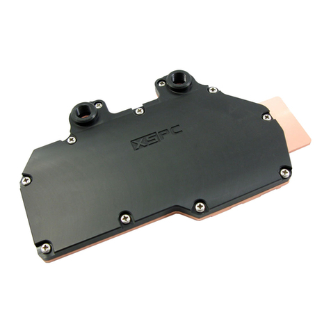
XSPC X2O User manual

Contents
1.1 Introduction P2
2.1 Package ontents P3
2.2 Features / Specification P3
3.1 Mounting the PU Water Block (Part 1) P4
3.2 Mounting the Radiator P5
3.3 Installing the 80mm adapter brackets P6
3.4 onnecting the tubing P7
3. Filling the System P8
3.6 Mounting the PU Water-Block (Part 2) P9
3.7 Final Installation P10
4.1 Maintenance P10
.1 Frequently Asked Questions P11
6.1 Disclaimer P12
7.1 Support ontact Information P12
1.1 - Introduction
Thank you for purchasing the XSP X2O PU water-cooling kit.
The X2O water-cooling kit is designed as a low noise solution to
the ever increasing heat output of modern processors. The X2O
kit is easily expandable and is powerful enough to handle the
addition of a GPU or chipset water-block.
Please read this guide carefully before attempting to install this
DIY water-cooling kit. If you do not understand the installation
process please contact XSP or your retailer.
Page 2/12

2.1 - Package Contents
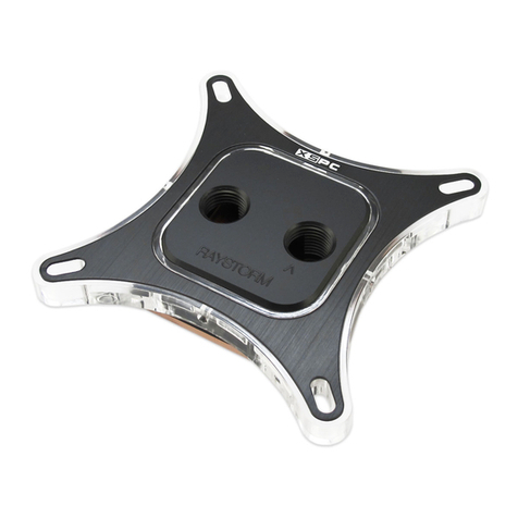
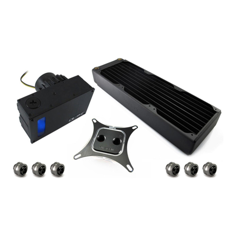
•PU Block with 10/8mm fittings
•Universal PU Mount
4x bolts, 12x washers, 4x nuts, 4x springs, 4x knurled nuts
•120mm Radiator with 10/8mm fittings *
4x 30mm Screws, 4x 10mm Screws, 1x 120mm Fan Gasket
•Low Noise 120mm ase Fan
•Radiator 80mm fan mount kit and blanking plate
4x Small Screws, 4x Large Screws, 4x racket, 8x Washer
•12V D Pump unit with 10/8 fittings
•lear 10/8mm tubing (10mm Outer diameter, 8mm Inner)
•Anti orrosive Water Additive
•Thermal Paste
•Blue LED with 4 pin molex.
•3 to 4 pin adapter cable
Radiator avaliable in Single Pass(Crossflow), Dual Pass horizontal and Dual Pass vertical versions.
2.2 - Features / Specification
CPU Water-Block
Materials opper base with plated brass top
Dimensions 57x57mm
Port thread size
Weight
G1/4”
275g
Universal CPU Mount
Material Plated brass
Dimensions 100x81x2mm
Designed for:
*Requires mounting holes
AMD Sockets 939, 754, 940, A/462
Intel Sockets 775, 478, 603, 604
Radiator
Materials opper and brass
Dimensions 316x139x45mm
Port thread size G1/4”
120mm Fan
Power 12V, 0.18A, 3pin connector
Speed / Airflow
Noise Level
1700 Rpm, 65.12 FM
30dBA
12V Pump/Reservoir
Reservoir Materials Anodized aluminium and Acrylic reservoir
Dimensions 88x56x88mm
Port thread size G1/4”
Pump Specification 400l/h , 1.65m head, ~1800rpm, 12V, 9.5W
Page 3/12

3.1 - Mounting the CPU Water Block (Part 1)
Note: Installation of the mounting bolts may require you to remove the
plastic cage around the CPU socket before installation can continue.
Note: The images below show the mount being installed on a Socket
462(A) motherboard but the installation process is the same for all
sockets.
The installation of the PU water-block is split into 2 parts. In the first part you will install the bolts for the
universal mount. Please follow the steps below.
1. Place a plastic washer over the bolt to prevent an electrical short
2. Push the bolt through one of the socket holes around the socket from the back of the board.
3. Turn the board over and place a second plastic washer over the bolt followed by a nut. Then secure the
bolt in place by gently tightening the nut.
4. Repeat the process for the 4 bolts or two if using an A64 based system
. Once all bolts are in place the motherboard will be ready to be installed into the P case.
Installation of the CPU water-block continues on page 9. Part 2 of the water-block takes place after the
tubing has been connected and the system has been filled.
Page 4/12
Nut
Plastic Washer
Motherboard
Bolt
Plastic Washer

3.2 - Mounting the Radiator
Note: It is advisable to temporarily mount the radiator before you
connect the tubing. This will make it easier to measure and cut
the tubing to the correct length.
The radiator can be mounted in a variety of places inside or
outside of your case. The position depends on the amount of
room, the size of fan mounts available and the style of radiator in
the kit.
The radiator is designed to be mounted to a 120mm fan mount but
is also supplied with brackets for mounting on a 80mm mount or
mounting externally on a flat surface. (See page 6)
The radiator can be positioned either way up and both tubing
connectors can be used for either the inlet or the outlet.
Example radiator positions
The radiator can be secured to a 120mm fan mount by using the provided 10mm screws.
Once the radiator has been mounted and you are happy with its position, measure and cut the tubing to size.
After the tubing has been cut to size remove the radiator from the case.
Note: If mounting the radiator externally you will need to route the tubing through
the back plate before connecting all of the fittings.
Mounting the radiator using the 80mm adapter brackets is detailed on Page 6.
Page 5/12

3.3 - Installing the 80mm adapter brackets
The X2O water-cooling kit radiator is designed to be mounted in most P
cases without the need for modification or cutting. If no 120mm mounts are
available in your case you should use the pictured brackets to mount the
radiator to an 80mm fan mount.
If mounting the radiator externally, a back plate is provided for routing the
tubing and power cable back into the case.
1. Place the radiator fan on a flat surface and attach the four brackets to the
chrome shroud using the provided screws and rubber washers.
Radiator < Washer < Non-threaded end of bracket < small screw
2. Line up the radiator and four mounts to the 80mm fan mount. Use the four longer screws to fix the mounts
to the P case.
Threaded end of bracket < Washer < Case panel < Longer screw
Mounting the radiator on a flat panel
The 80mm adapter brackets can also be turned around and used to mount
the radiator externally on a flat panel. Mounting in this way will require
some modification of the case to secure the radiator.
Note: Make sure the radiator is firmly secured to avoid rattling and vibrations
Page 6/12
Screw thread
No Screw thread

3.4 - Connecting the tubing
Note: efore connecting the tubing make sure you place the universal mount over the CPU water-block.
This will not be possible once all the tubing has been connected.
The pump, radiator and water-block need to be connected in a loop in series. To find the easiest route for the
tubing we recommend that you place the water-block, pump and radiator loosely in position and cut the
tubing to the required length. The tubing will have a natural curve and when bending the tubing you should
follow this direction.
After measuring the tubing the water-block, pump and radiator should be removed from the case until the
system has been filled and leak tested.
Note: To avoid leaks it is important that all tubing is cut straight.
Using compression fittings
onnecting the tubing can be done in 3 easy steps.
1. Place the screw cap over the tubing and push the open end of the tubing over the barbed fitting.
2. Move the cap down the tubing and place over the barbed fitting
3. Tighten the screw cap by hand until the tubing is secured
Suggested circuit order
Pump outlet Radiator CPU lock Return to pump
Although a suggested order is given the easiest and shortest route
for the tubing is normally the best. Each of the three components
can placed in the circuit in any order as long as a complete loop is
made.
Note: Avoid kinks in the tubing. Any kinks will effect the flow rate
of the water and degrade performance.
Inlets and outlets
Either connector on the PU block and Radiator can be used for the inlet
or outlet. To avoid trapped air the chosen outlet should not be positioned
below the chosen inlet.
The pump inlet(Return) and outlet are shown in the photo.
Page 7/12
1 2 3

3. - Filling the System
Water Additive
The water-cooling kit should be filled with a mix of de-ionized
water and the supplied water additive. Please see the bottle for
required concentration and mixing instructions.
Filling the reservoir
Once the tubing has been connected the next stage is to fill the
reservoir and remove the air from the system.
Filling the reservoir and system is an easy process but care
should be taken to avoid spillage.
1. Remove the filler cap
2. Pour a small amount of the mixed liquid into the reservoir
until full.
3. onnect the 3 pin power connector to start the pump
(see: how to start the pump outside of the PC)
4. Keep refilling the reservoir while the system is slowly filled
and the air is removed
. To help remove the air from the radiator gently rock the
radiator. Avoid putting undue stress on the tubing and connectors.
6. Once the system and reservoir appear full turn off the pump and leave to settle for 2min then Re-
Start the pump and top up if necessary.
7. Once you are happy that all the air has been removed from the system top up the reservoir then
replace the filler cap and finally turn off the pump.
Note: It is normal for the pump to make noise while the air is
removed from the system. Once the air has been removed the
noise will reduce to near silence.
How to start the pump outside of the PC.
Normally the pump will run from a 3 pin connector on your motherboard but this is not suitable while filling
the system for the first time. To fill the circuit you will need to start the pump with an external 12V D source.
It is possible to use an ATX PSU using the provided 3 to 4 pin adapter to connect the pump to the PSU. As
the PSU is not connected to a motherboard you will need to start it using an ATX bridging clip or by
connecting pins 13 and 14 on an ATX 20pin connector.
Note: We reccomend that you leak test the system for at least 24hours before use in a PC.
Page 8/12

3.6 - Mounting the CPU Water-Block (Part 2)
Note: The tubing should be connected to the CPU water-block at this stage. The tubing was intentionally left
out of the photos on this page so the mounting system is clearily visable.
1. Remove the film from the base of the water-block
2. Apply a thin layer of thermal paste to the PU or as directed by manufacturer's instructions
3. Place the waterblock over the PU socket and line up the universal PU mount with the bolts.
4. Place the PU water-block onto the PU and slide the universal mount down into place.
. Place a plastic washer over each bolt followed by a spring.
6. Place a knurled nut over a bolt and tighten gradually to the required pressure. To avoid applying uneven
pressure two opposite knurled nuts should be tighted at once.
Warning: Overtightening may cause damage to your PU.
Page 9/12
Spring
Plastic washer
Knurled nut
Universal PU lip
Bolt

3.7 - Final Installation
Once the PU water-block is in place you are ready to re-install the radiator and pump into your case.
Please take care not to put unnecessary force on the tubing connectors while moving the components.
Finally connect the fan and pump to the 3pin headers on the motherboard or to a 4 pin molex connector
using the provided adapters.
Once all the components are secured in place, your system is ready for use.
4.1 - Maintanance
To ensure correct operation after installation it is recommended that you do the following:
•Inspect the system for leaks on a regular basis
•heck the water level regularly and top up in necessary
•Drain the system and replace the liquid every 8-12 months
•Keep tubing out of direct sunlight
•Only use in enviroments between 0 and 40
•Remove dust from the radiator to avoid loss of airflow
Page 10/12

.1 - Frequently Asked Questions
Most questions can be answered by throughly reading this manual. If your question can not be answered by
the suggestions below or the installation guide please contact XSPC or your retailer
Question Answer
I have bubbles in the water, how do I get rid
of this.
The bubbles in the water will usual leave the system
within 24hours.
Shutting down and leaving the the bubbles to settle
before restarting can help.
My pump is making a noise heck your water level. If the water level drops air will get
into the pump.
It is normal for some noise upon startup but this will fade
quickly.
My CPU temperature seems high what
could be wrong ?
1. heck the pump is running.
2. Make sure the airflow to the radiator is not restricted.
3. Double check all of the air has been removed from the
radiator.
4. Inspect the tubing for kinks and twist which may
restrict flow.
5. Remove the PU waterblock, re apply thermal paste
and re-mount the block.
an I use tap water to fill the system? No tap water can contain impurities which may cause a
build up inside the components.
You are advised to use de-ionized water mixed the
provided additive
Where can I buy de-ionized water Most supermakets and car maintanace shops will sell it.
It is commonly used for filling Irons and topping up car
batteries.
Water is leaking from the connectors This is caused by incorrect installation. Drain the system
and reconnect the tubing.
Water is leaking from the radiator, PU
block or pump.
In the highly unlikely event of a leak from one of the
components drain the system and contact your retailer.
Page 11/12

6.1 - Disclaimer
The X2O liquid cooling system is sold as a DIY kit. You are responsible for correct installation and
maintenance of this equipment. XSP will not be held responsible for any loss of property/data or
personal harm caused by the improper use or installation of this equipment.
The components in this kit are supplied with a 12 month warrantly against failure. This excludes
consumable items such as tubing, water-addtives and thermal paste. This also excludes failures
which are a direct result of impropper use.
7.1 - Support Contact Information
UK and Mainland Europe
www.xs-pc.co.uk
North America and Asia
www.xs-pc.co.uk
Copyright© XSPC 2005
Page 12/12
Table of contents
Other XSPC Computer Hardware manuals
Popular Computer Hardware manuals by other brands

Intersil
Intersil ISL6423B quick start guide

Bridgeworks
Bridgeworks Appliance a003 Hardware manual

Renesas
Renesas E2 Lite user manual

Analog Devices
Analog Devices UG-397 user guide

Delta Electronics
Delta Electronics Power Factor Corrector PFC4116V Series Specification sheet

miniDSP
miniDSP Home Theater Series user manual

ATTO Technology
ATTO Technology FastStream SC 7700 quick start guide

EK-Quantum
EK-Quantum Power2 Kit P360 Series installation manual

TAMS
TAMS 60488 Installation & operation

Texas Instruments
Texas Instruments TMS320C6457 Quick setup guide

Multitech
Multitech RouteFinder RF802WLC quick start guide

Abus
Abus TVAC21000 user manual