Xterra 16804732000 User manual

Model:16804732000
ERG200 ROWER
OWNER’S MANUAL
PLEASE CAREFULLY READ THIS ENTIRE MANUAL BEFORE OPERATING YOUR NEW ROWER

customerservice@dyaco.caDyacoCanadaInc2017
2
TABLEOF
CONTENTS
BeforeYouBegin..............................................................................................3
ImportantSafetyInstructions................................................................................4
ERG200AssemblyInstructions................................................................................8
OperationofYourNewRower........................................................................................12
Function...............................................................................................................13
UserDirection.......................................................................................................13
GeneralMaintenance...........................................................................................14
ExplodedViewDiagram.....................................................................................15
PartsList.............................................................................................................17
TroubleShooting................................................................................................19
Manufacturer’sLimitedWarranty......................................................................26
ATTENTION
THISROWERISINTENDEDFORRESIDENTIALUSEONLYANDISWARRANTEDFORTHEAPPLICATION.
ANYOTHERAPPLICATIONVOIDSTHISWARRANTYINITSENTIRETY.

3
BEFOREYOUBEGIN
ThankyouforchoosingtheXterraERG200Rower.Wetakegreatprideinproducingthisqualityproduct
andhopeitwillprovidemanyhoursofqualityexercisetomakeyoufeelbetter,lookbetter,andenjoy
lifetoitsfullest.It'saprovenfactthataregularexerciseprogramcanimproveyourphysicalandmental
health.Toooften,ourbusylifestyleslimitourtimeandopportunitytoexercise.TheXterraERG200
Rowerprovidesaconvenientandsimplemethodtobeginyourassaultongettingyourbodyinshape
andachievingahappierandhealthierlifestyle.Beforereadingfurther,pleasereviewthedrawingbelow
andfamiliarizeyourselfwiththepartsthatarelabeled.
ReadthismanualcarefullybeforeusingtheXterraERG200Rower.AlthoughDyacoCanadaInc.
constructsitsproductswiththefinestmaterialsandusesthehigheststandardsofmanufacturingand
qualitycontrol,therecansometimesbemissingpartsorincorrectlysizedparts.Ifyouhaveany
questionsorproblemswiththepartsincludedwithyourXterraERG200Rower,pleasedonotreturnthe
product.ContactusFIRST!Ifapartismissingordefectivecallustollfreeat1‐888‐707‐1880.Our
CustomerServiceStaffareavailabletoassistyoufrom8:30A.M.to5:00P. M . (EasternTime)Monday
throughFriday.Besuretohavethenameandmodelnumberoftheproductavailablewhenyoucontact
us.
Mid-Stabilizer
Transport Wheel
Rear Stabilizer
Sliding Rail
Pedals
Seat
Console
Handle Bars

4
IMPORTANTSAFETY
INSTRUCTIONS
WARNING‐Readallinstructionsbeforeusingthisequipment.
Donotoperatetherowerondeeplypadded,plushorshagcarpet.Damagetobothcarpetand
rowermayresult.
Beforebeginningthisoranyexerciseprogram,consultaphysician.Thisisespeciallyimportantfor
personsovertheageof35orpersonswithpre‐existinghealthconditions.
Keepchildrenundertheageof13awayfromthismachine.Thereareobviouspinchpointsand
othercautionareasthatcancauseharm.
Keephandsawayfromallmovingparts.
Neverdroporinsertanyobjectintoanyopenings.
Donotuseoutdoors.
Wearpropershoes.Highheels,dressshoes,sandalsorbarefeetarenotsuitableforuseonyour
rower.Qualityathleticshoesarerecommendedtoavoidlegfatigueorinjury.
Thisequipmentisnotintendedforusebypersonswithreducedphysical,sensoryormental
capabilities,orlackofexperienceandknowledge,unlesstheyhavebeengivensupervisionor
instructionconcerninguseoftheequipmentbyapersonresponsiblefortheirsafety.
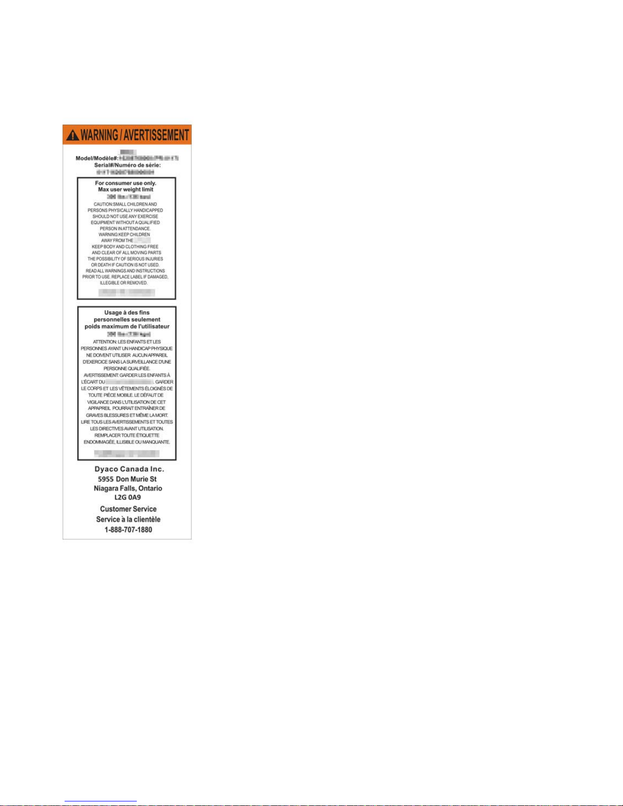
Userweightshouldnotexceed:250lbs(113kgs)
SAVETHESEINSTRUCTIONS‐THINKSAFETY!
CAUTION!!Pleasebecarefulwhenunpackingthecarton.

5
WARNINGDECAL
REPLACEMENT
Thedecalshownbelowhasbeenplacedontherower.Ifthedecalismissingorillegible,pleasecallour
CustomerServiceDepartmenttoll‐freeat1‐888‐707‐1880toorderareplacementdecal.

6
ERG200
PRE‐ASSEMBLYCHECKLIST
NO:1 NO:28 NO:11 NO:14L/R
NO:26 NO:3 NO:9 NO:17
Part No. Description Q'ty
1 Main Frame 1
3 Front Stabilize
r
1
9 Monito
r
1
28 Rear Stabilize
r
1
11 Seat 1
14L Left Pedal 1
14R Ri
g
ht Pedal 1
17 Pedal Support Tube 1
26 Slidin
g
Rail 1
Hardware Ba
g
1
Manual 1

7
ERG200
ASSEMBLYPACKCHECKLIST
Part No. Description Q’ty
2 Allen Bolt M8*75 2
5 End Caps 2
6 Curved Washer Φ8*Φ20 2
7 Spring Washer Φ8 2
12 Allen Bolt M6*12 4
13 Washer Φ6*Φ17 4
15 Axle for Pedal 2
19 Carriage Bolt M8*45 2
34 Domed Nut M8 2
22 Collar 4
23 Allen Bolt M8*20 4
24 Allen Bolt M8*16 10
25 Washer Φ8*Φ17 12
76 Allen Key 4mm 2
77 Allen Key 6mm 1
75 Box Wrench 1
Note: Above parts are all the parts needed to assemble this machine. Before you
start to assemble, please check the hardware packing to make sure they are
included.

8
ERG200
ASSEMBLYINSTRUCTIONS
1 STABILIZERS, CONSOLE MAST & CONSOLE
10
21
62
9
1
3
27
6
1. Attach the front stabilizer (3) to the main frame (1). Secure using
two allen bolts (2), two curve washers (6) and two spring washers
(7).
2. Connect the computer sensor wire (21) to the back of the
computer (9).
3. Attach the computer (9) to the computer bracket (62) and fasten
with two screws (10).
NOTE: Ensure that the wires are not pinched behind the computer.
Please insert two ‘’AA” batteries (not included) at the back of the console.
2 Allen Bolts (#2)
2 Spring Washers
(#7)
2 Curved Washers
(#6)
Hardware Step 1

9
2ATTACHING PEDALS
12
13
14L 14R
15
15
12
13 17
19
25
34 13
12
1
55
1. Attach the left pedal (14L) to the left bracket of pedal
support tube (17). Secure using one axle for pedal (15),
two sets of allen bolt (12) and washer (13).
2. Repeat the same procedure for right pedal.
3. Attach the pedal support tube (17) to the bottom of main
frame (1). Secure using two sets of carriage bolt (19),
washer (25) and domed nut (34).
4. Pull out the lock pin (55) from pivot on u type connect tube
(58). Flip down the bracket and insert the lock pin (55)
back to the pivot to lock the bracket in horizontal position.
Hardware Step 2
2 Carriage Bolt (#19)
Left Pedal (#14L)
Right Pedals (#14R)
2 Axle for Pedal (15)
2 Allen Bolt (#12)
2 Washers (13)
2 Washers (25)
2 Domed nuts (34)

10
3 ATTACHING SLIDING RAIL FRAME
24
25
22
23
22 23
25
24
1
58
22
23
22 23
5L
5R
11
28
24
25
26
1. Insert the sliding rail (26) to the u type connect tube (58). Secure
using four sets of allen bolt (24) and washer (25) on the bottom,
two sets of allen bolt (24) and washer (25) on the top.
2. Attach collar (22) to each side of the track on this end of sliding
rail (26). Secure using one allen bolt (23).
3. Slide the Seat (11) onto the sliding rail.
4. Repeat same procedure for other two collars (22) to the other
end of sliding rail (26).
5. Attach the end cap for sliding rail (5L/R) to the back of sliding rail
(26).
6. Attach the rear stabilizer (28) to sliding rail (26). Secure using
four sets of allen bolt (24) and washer (25).
Hardware Step 3
10 Allen Bolt (#24)
10 Washers (#25)
4 Allen Bolt (#23)

11
4 FOLDING ROWER
55
55
1. Pull out the lock pin (55) and lift up the sliding rail to unfold the rower.

customer[email protected]a
DyacoCanadaInc2017
12
OPERATIONOF
YOURROWER
GETTINGFAMILIARWITHTHECONTROLPANEL
ERG200CONSOLE
Key Functions
BUTTONS:
MODE: Press to select the desired function between: Scan, Time, Count, Calories and Total
Count.
SET: Press to set the values of time, count and calories
RESET: Press to reset your function value to zero.

customer[email protected]a
DyacoCanadaInc2017
13
FUNCTIONS
TIME: Display your elapsed workout time up to 99:59
COUNT: Accumulates total working strides during your workout from 0 up to 9999.
CALORIE: Displays the cumulative calories burned at any given time during your workout up to
999 kcal. This data is a rough guide for comparison of different exercise session which cannot
be used as medical treatment)
TOTAL COUNT: Displays the total cumulative number of strides
NOTE:
1. Monitor uses 2 AA battery
2. If the monitor is illegible or partial segments appear replace the batteries
3. Computer automatically shut down after 4 minutes without any signal input.
The monitor will turn on automatically by pressing any key or starting your exercise program.
User Direction
HOW TO MOVE THE ROWER
The rower can be easily moved from room to room.
Remove the lock pin, fold the sliding rail up and reinsert
Pin to secure the sliding rail in position. Grasp the rear
support tube and pulling back on tube, tip machine towards
you.
HOW TO LEVEL THE ROWER
The rower is equipped with adjustable end caps. If the
unit is wobbly, please turn the wheel on the leveling caps
of the rear stabilizer to level the unit.

14
GENERALMAINTENANCE
Thesafetyofthisproductcanbemaintainedonlyifregularperiodicchecksaremade.Mostcheckscan
beperformedonceaweek.However,somechecksshouldbemadebeforeeachworkout,andare
indicatedassuchbelow.
Checks
•Checkthatpedalshardwareissecure,hardwarecanworklooseovertime.
•Checkthatstabilizerboltsaretight,checkbeforeeachworkout.
•Checkthatslidingrailissecure,ifnot,tighten,checkbeforeeachworkout.
•Shouldapartbecomedefective,replaceitimmediately.Donotallowuseoftheequipmentuntilit
hasbeenrepaired.
Cleaning
Adampclothissufficienttocleanmostsurfacesofthisunit.Becarefulnottodripwateronthe
monitor.Amildliquidsoapmaybeaddedifneeded.

15
EXPLODEDVIEWDIAGRAM
2
3
4
4
5L
5R
5L5R
7
6
11
12
13
14L 14R
15
15
12
13 17
19 20
20
22
22
22
22
23
23
23
23
24
25
24 25
24
24
25
25
25 26
28
2929
30
31
33
32
34 13
12
35
27
27
20
20
1
58
10
21
62
8
1
58
9

16
36
37
38L
38R
3939
43
42
42
44
46
47
48
5049
52
23
23
7
7
54
5455
56
56
57
58
5959
5959
59
60
6162
64
6566
67
67
68
31
31
3145
45
21
41
40
41
4071
51
45
8
63
69
70
72
73
74
4545
45
45
45
31
25
53

17
PARTSLIST
KeyPartNumberDescription Q'ty
1 7320001 Main frame 1
2 7320002 Allen blot M8*75 2
3 7320003 Front stabilizer 1
4L/R 7320004L/7320004R End cap for front stabilizer 1set
5 7320005 End cap for sliding rail 4
6 7320006 Curve washer Ф8*Ф20 2
7 7320007 Spring washer Ф8 4
8 7320008 8-level tension knob 1
9 7320009 Computer 1
10 7320010 Screw M5*10 2
11 7320011 Seat 1
12 7320012 Allen bolt M6*12 4
13 7320013 Washer Ф6*Ф17 4
14L 7320014L Pedal L 1
14R 7320014R Pedal R 1
15 7320015 Axle for pedal 2
17 7320017 Pedal support tube 1
18 7320018 Bracket for rope pulley 2
19 7320019 Carriage bolt M8*45 2
20 7320020 End cap for mid stabilizer 2
21 7320021 Computer sensor wire 1
22 7320022 Collar 4
23 7320023 Allen blot M8*20 6
24 7320024 Allen blot M8*16 10
25 7320025 WasherФ8*Ф17 18
26 7320026 Sliding rail 1
27 7320027 Screw M5*15 4
28 7320028 Rear support tube 1
29 7320029 End cap for rear stabilizer 2
30 7320030 Allen bolt M6*20 2
31 7320031 Nylon nut M8 9
32 7320032 Wheel 4
33 7320033 Sleeve 4
34 7320034 Domed nut M8 2
35 7320035 Seat support 1
36 7320036 Belt 1
37 7320037 Rope Pulley w/rope 1
38L 7320038L Chain cover L 1
38R 7320038R Chain cover R 1

18
KeyPartNumberDescription Q'ty
39 7320039 Flywheel adjustor 2
40 7320040 Nylon nut M6 2
41 7320041 Eye bolt 2
42 7320042 Flange nut 2
43 7320043 Flywheel 1
44 7320044 Hex head bolt M8*105 1
45 7320045 Self tapping screw ST5*15 8
46 7320046 Small bushing 2
47 7320047 Magnetic assembly 1
48 7320048 Rope pulley cover 1
49 7320049 Hex head nut 2
50 7320050 Hex head bolt M6*25 1
51 7320051 Sensor bracket 1
52 7320052 Small cover 1
53 7320053 Powder bushing 2
54 7320054 Washerф8*ф25 2
55 7320055 Lock pin 1
56 7320056 Bushing 2
57 7320057 Axle 1
58 7320058 U type connect tube 1
59 7320059 Self tapping screw ST5*15 6
60 7320060 Spring 1
61 7320061 Grommet 2
62 7320062 Computer bracket 1
63 7320063 Handlebar 1
64 7320064 Axle for computer post 1
65 7320065 Idler pulley 1
66 7320066 Axle for idler 1
67 7320067 Knob 2
68 7320068 Self tapping screw ST4*16 2
69 7320069 Foam grip for handlebar 2
70 7320070 End cap for handlebar 2
71 7320071 Mesh belt 1
72 7320072 Upper cover for handlebar 1
73 7320073 Bottom cover for handlebar 1
74 7320074 Self tapping screw ST4 2
75 7320075 Box wrench 1
76 7320076 Allen key 4mm 2
77 7320077 Allen key 6mm 1

19
TROUBLESHOOTING
Problem Cause Solution
Monitor does not display
Batteries not Installed Install batteries
Sensor wire not connected Ensure the sensor wire is connected
properly to the computer
No speed or count displays
on
the monitor
Sensor wire not connected Ensure the sensor wire is connected
properly to the computer
Sensor wire not working properly Replace sensor wire
Monitor not working properly Replace monitor
No tension
Magnetic assembly not working
properly Replace magnetic assembly
Tension knob defective Replace the tension knob
Tension needs Adjustment Turn tension adjustment knob
accordingly
Grinding Noise
Idler pulley defective Replace idler pulley
Flywheel defective Replace flywheel
Squealing V-belt slipping Adjust v-belt

20
TRAINING
GUIDELINES
EXERCISE
Exerciseisoneofthemostimportantfactorsintheoverallhealthofanindividual.Listedamongits
benefitsare:
Increasedcapacityforphysicalwork(strengthendurance)
Increasedcardiovascular(heartandarteries/veins)andrespiratoryefficiency
Decreasedriskofcoronaryheartdisease
Changesinbodymetabolism,e.g.losingweight
Delayingthephysiologicaleffectsofage
Physiologicaleffects,e.g.reductioninstress,increaseinself‐confidence,etc.
BASICCOMPONENTSOFPHYSICALFITNESS
Therearefourallencompassingcomponentsofphysicalfitnessandweneedtobrieflydefineeachand
clarifyitsrole.
Strengthisthecapacityofamuscletoexertaforceagainstresistance.Strengthcontributesto
powerandspeedandisofgreatimportancetoamajorityofsportspeople.
MuscularEnduranceisthecapacitytoexertaforcerepeatedlyoveraperiodoftime,e.g.itisthe
capacityofyourlegstocarryyou10Kmwithoutstopping.
Flexibilityistherangeofmotionaboutajoint.Improvingflexibilityinvolvesthestretchingof
musclesandtendonstomaintainorincreasesuppleness,andprovidesincreasedresistanceto
muscleinjuryorsoreness.
Cardio‐RespiratoryEnduranceisthemostessentialcomponentofphysicalfitness.Itistheefficient
functioningoftheheartandlungs
AEROBICFITNESS
Thelargestamountofoxygenthatyoucanuseperminuteduringexerciseiscalledyourmaximum
oxygenuptake(MVo2).Thisisoftenreferredtoasyouraerobiccapacity.
Theeffortthatyoucanexertoveraprolongedperiodoftimeislimitedbyyourabilitytodeliveroxygen
totheworkingmuscles.Regularvigorousexerciseproducesatrainingeffectthatcanincreaseyour
aerobiccapacitybyasmuchas20to30%.AnincreasedMVO2indicatesanincreasedabilityoftheheart
topumpblood,ofthelungstoventilateoxygenandofthemusclestotakeupoxygen.
AnaerobicTraining
Thismeans“withoutoxygen”andistheoutputofenergywhentheoxygensupplyisinsufficienttomeet
thebody’slongtermenergydemands.(Forexample,100metersprint).
TheTrainingThreshold
Thisistheminimumlevelofexercisewhichisrequiredtoproducesignificantimprovementsinany
physicalfitnessparameter.
This manual suits for next models
1
Table of contents
Other Xterra Home Gym manuals
Popular Home Gym manuals by other brands

Epic
Epic FLATBENCH GZFW20611 owner's manual

ParaBody
ParaBody PBF010A Assembly instructions

CYBEX
CYBEX VR3 Prone Leg Curl Owner's and service manual

Body Solid
Body Solid G10B owner's manual

Cap Strength
Cap Strength FM-7006 Owner's manual and assembly guide

Hammer Strength
Hammer Strength HDADJ Assembly instructions