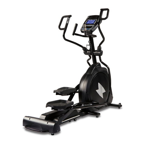
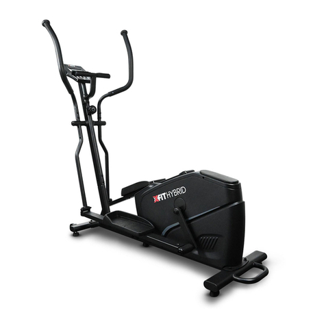
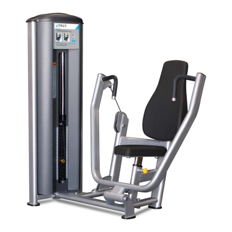
Xtreme XFit ELITE User manual

Elliptical
User’s Manual
The specifications of this product may vary slightly from the illustrations and are subject to change without
notice.

IMPORTANT SAFETY NOTICE
Note the following precaution before assembling and operating the machine.
1. Assemble the machine exactly as the descriptions in the instruction manual.
2. Check all the bolts, nuts and other connections before using the machine for the first time to ensure
the machine is in the safe condition.
3. Set up the machine in a dry level place and keep it away from moisture and water.
4. Place a suitable base (e.g. rubber mat, wooden board etc.) beneath the machine in the area of
assembly to avoid dirt.
5. Before beginning the training, remove all objects within a radius of 2 meters from the machine.
6. Do not use aggressive cleaning articles to clean the machine. Only use the supplied tools or
suitable tools of your own to assemble the machine or repair any parts of machine. Remove drops
of sweat from the machine immediately after finishing training.
7. Your health can be affected by incorrect or excessive training. Consult a doctor before beginning
the training program. He can define the maximum setting (Pulse, Watts, Duration of training etc) to
which you may train yourself and can get precise information during training. This machine is not
suitable for therapeutic purpose.
8. Only do training on the machine when it is in correct working way. Use only original spare parts for
any necessary repairs.
9. This machine can be used for only one person’s training at a time.
10. Wear training clothes and shoes that are suitable for fitness training with the machine. Your
training shoes should be appropriate for the trainer.
11. If you have a feeling of dizziness, sickness, or other abnormal symptoms, please stop training and
consult a doctor immediately.
12. People such as children and handicapped persons should only use the machine in the presence
of another person who can give aid and advice.
13. The power of the machine increases with increasing the speed, and the reverse. The machine is
equipped with adjustable knob that can adjust the resistance.
14.Maximum user’s weight is 120kg.
CAUTION! The company does not have no responsibility for causing damage due to misuse of the product and
non-compliance with the instructions for use.
THE WARRANTY IS NOT VALID IF: The machine is placed outdoors or exposed to sun and dust.
Check and tighten the screws at regular intervals, as they may loosen due to vibrations. Damage that
may be caused by a lack of maintenance is not covered by the warranty.
EXPLOADED DIAGRAM
NOTE: Most of the listed assembly hardware has been packaged separately, but some hardware
items have been preinstalled in the identified assembly parts. In these instances, simply remove and
reinstall the hardware as assembly is required. Please reference the individual assembly steps and
make note of all preinstalled hardware.

PARTS LIST
NO.
DESCRIPTION
Qty
NO.
DESCRIPTION
Qty
1
Main frame
1
32
BushingΦ18XΦ10 X11
4
2
Front stabilizer
1
33
Hex bolt M8X45
6
3
Rear stabilizer
1
34L/R
Pedal (L/R)
1pr.
4
Handlebar post
1
35
Cross tapping screw
ST4.2X18
10
5
Armrest
1
36L/R
Linkage shield
2pr.
6 L/R
Handlebar (L/R)
1pr.
37
Hex bolt Φ12 XM10X80 2
7 L/R
Swing bar(L/R)
1pr.
38
Flat washer D12XΦ24X1.5
2
8 L/R
Pedal support (L/R)
1pr.
39
Axle bushing Φ12XΦ32 X15
4
9
Oval end cap
2
40
Plastic axle bushing
Φ16XΦ31 X23
6
10
Allen screw M8X40XL12
2
41
Cross tapping screw
ST3.5X10
8
11
Transport wheel
2
42a/b
Swing bar shield
2pr.
12
Flat washer D8XΦ16 X1.5
12
43
Arc washer D8XΦ19 X1.5XR30
4
13
Nylon nut M8
12
44
Carriage bolt M8XL45
4
14
Hex bolt M10
4
45 L/R
Handlebar foam grip
1pr.
15
Adjusting foot pad
4
46
Mushroom end cap
2
16
Arc washer d8X2XΦ25 XR39
4
47
Computer
1
17
Allen bolt M8XL58
4
48
Round end cap
2
18
Spring washer D8
12
49
Pulse sensor
2
19
Oval end cap
2
50
Armrest foam grip
2
20
Crank
2
51 a/b
Computer shield
1pr.
21
Waveform washer
Φ17XΦ23 X0.3
4
52
Cross screw M4X10
4
22
Plastic bushingΦ24X16XΦ16.1
4
53
Allen screw M8X16
8
23 L/R
Connecting joint (L/R)
1pr.
54
Cross screw M5X55
1
24
D-shape washer
Φ28XΦ16.2 X14XB5
4
55
Arc washer D5
1
25
Washer D10
4
56
Long axle
1
26
Allen bolt M10X20
4
57
Tension controller
1
27
Crossing screw M5X10
4
58
Post shield
1
28 a/b
Connecting joint cover
2pr.
59
Extension wire
1
29
Hex bolt M10X55
2
60
Sensor wire
1
30
Flat washer D10XΦ20X2
4
61
Tension controller cable
1
31
Nylon nut M10
4
62
Pulse sensor wire
2

PREPARATION: Before assembling, make sure that you will have enough space around the item;
Use the present tooling for assembling; before assembling, please check whether all needed parts
are available. It is strongly recommended this machine to be assembled by two or more people to
avoid possible injury.
ASSEMBLY INSTRUCTION
Step 1:
Fix the Front stabilizer (2) and
Rear stabilizer (3) to the Main
frame (1) with Allen bolt (17),
Spring washer (18) and Arc
washer (20).
Step 2:
A: Insert the Post shield (58) into
the Handlebar post (4).
B: Connect the Sensor wire (60)
well with Extension wire (59) and
then connect the Tension wire from
Tension controller (57) well with
Tension controller cable (61) as
Picture A shown. Finally fix the
Handlebar post (4) to the Main
frame (1) with Allen screw (53),
Spring washer (18) and Flat
washer (12) and then slid down
the Post shield (58).

Step 3:
A: Fix the Swing bar (7L/R) on the long axle of the Handlebar post (4) with Allen screw (26), Spring
washer (25), D-shape washer (24), Waveform washer (21) and Long axle (56) as shown. Please
do not tighten them this time.
B: Attach the Pedal support (8L/R) with connect joint to the Crank (20) using Allen bolt (26), Spring
washer (25), D-shape washer (24) and Waveform washer (21) as shown.
C: Attach the Swing bar (7L/R) to Pedal support (8L/R) using Hex bolt (37), Flat washer (38) (30) and
Nylon nut (31). Then tighten Allen screw (26), Hex bolt (37) and Nylon nut (31).
D: Fix the Pedal (34L/R) to the Pedal support (8L/R) with Hex bolt (33), Flat washer (12) and Nylon
nut (13).

Step 4:
A: Fix the Handlebar (6L/R) onto the Swing bar (7L/R) using Carriage bolt (44), Arc washer (43) and
Nylon nut (13).
B: Pull the Pulse sensor wire (62) through the Handlebar post (4) and then out of the hole of the
computer bracket. Fix the Armrest (5) on the Handlebar post (4) with Allen screw (53) and Spring
washer (18).
CAUTION! During exercise, heavy sweating can cause mechanical and electrical damage to the machine. Like
any other liquid substance, sweat is capable of causing damage mainly to the electrical parts of the machine
(dial, cables, etc.). The best solution is to use a towel during exercise and wipe the machine after each use to
avoid any unwanted damage.

Step 5:
A: Fix the Swing bar shield (42 a/b) to swing bar (7L/R) with Cross tapping screw (41) as shown.
B: Attach the Linkage shield (36L/R) to the joint between the Pedal support (8L/R) and Swing bar
(7L/R) using cross tapping screw (35) as shown.
C: Fix the connecting joint cover (28a/b) on the connecting joint (23L/R) with cross screw (27) as
shown.

Step 6:
A: Connect the Pulse sensor wire (62) and Extension wire (59) with the wires coming from
the Computer (47), and then fix the Computer (47) onto the computer bracket of the
Handlebar post (4) with cross screw (52).
B: Fix the Computer shield (51a/b) on the handlebar post (4) with cross tapping screw (35)
as shown.
CAUTION! The heart rate sensor and calorie counter are not medical devices. Several factors can affect the
accuracy of the indications. The heart rate sensor is only intended as an aid during exercise to monitor your
heart rate in general.

INSTRUCTION MANUAL OF ST8900-67
BUTTON FUNCTIONS
DISPLAY FUNCTIONS
RPM
Displays the Rotation Per Minute. Display range 0~15~999
SPEED
Displays current training speed. Maximum speed is 99.9 KM/H or ML/H.
TIME
Count up - No preset target, Time will count up from 00:00 to maximum 99:59 with
each increment is 1 minute.
Count down - If training with preset Time, Time will count down from preset to 00:00.
Each preset increment or decrement is 1 minute between 01:00 to 99:00.
DISTANCE
Accumulates total distance from 00:00 up to 99.99 KM or ML. The user may preset
target distance data by pressing UP/DOWN button. Each incensement is 0.5
KM or
ML.
CALORIES
Accumulates calories consumption during training from 0 to maximum 9999 calories.
(This data is a rough guide for comparison of different exercise sessions which cannot
be used in medical treatment.)
PULSE
User may set up target pulse from 30 to 199, and computer buzzer will beep when
actual heart rate is over the target value during workout.
OPERATION PROCEDURE
1. Install batteries to power on the computer, LCD will display all segments for 2 seconds with
long beep sound.
2. User may press SET to select 4 workout modes from G1, G2 to G4, and press MODE to enter.
3. Workout in G1 mode:
In G1 mode, user may preset TIME, DISTANCE, CALORIES and PULSE by pressing SET button and
MODE for confirmation. User may start workout after setup exercise value, and “STOP” sign will
disappear, all values will count down to zero. Once one of 4 values count to zero, computer buzzer
will beep for 8 seconds, press any button may stop buzzer.
Biking animation will move forward every 3 km, and PC speed will be the same as user.
MODE
To confirm all setting.
SET
To set up each exercise value of TIME, DISTANCE, CALOIRES and PULSE.
Hold on pressing the button to speed up setting.
RESET
To clear settings of TIME, DISTANCE, CALORIES and PULSE.
Hold on pressing the button to power on the console again.
RECOVERY
To test heart rate recovery status.

Workout in G2, G3 and G4 racing modes:
In G2, G3 and G4 racing modes, TIME preset is fixed in 20 minutes, the biking icon will move forward
for total 8 steps. Different racing modes have different preset speed in PC side. During workout, user
needs to follow up PC’s speed in order to win the racing game.
When time countdown to 0:00, STOP symbol will illuminate, and console will beep for 8 seconds. If
user can follow up with PC speed for at least 60%, console will define that user win the game and
show up “U-Win”; on the contrary, the console will show “P –Win.

4. RECOVERY
After workout for a period of time user may press RECOVERY button in standby mode with pulse
signal input (hold on both hands-on hand grips) to test heart rate recovery status. All functions will
turn off, console will display PULSE value and TIME counting down from 0:60.
As soon as 00:00 is reached, the bottom area of display will show your heart rate recovery status with
the grade F1, F2,… F6. F1 is the best, and F6 is the worst. You may keep exercising to improve the
heart rate recovery status day by day from F6 up to F1.
** Press the RECOVERY button again to return the main display.
NOTE :
1. The console requires power supply for SUM3 AA (1.5V) batteries X 2pcs.
2. Without RPM or PULSE signal input for 4 minutes, computer will enter into sleep mode (for
power-saving). User may start workout t or press any button to wake the console up.

USING YOUR BIKE
Using your bike will provide you with several benefits. It will improve your physical fitness,
tone your muscles and in conjunction with a calorie-controlled diet, help you lose weight.
WARM-UP PHASE
The purpose of warming up is to prepare your body for exercise and to minimize injuries.
Warm up for two to five minutes before strength-training or aerobic exercising. Perform
activities that raise your heart rate and warm the working muscles. Activities may include
brisk walking, jogging, jumping jacks, jump rope, and running in place.
STRETCHING
Stretching while your muscles are warm after a proper warm-up and again after your strength
or aerobic training session is very important. Muscles stretch more easily at these times
because of their elevated temperature, which greatly reduces the risk of injury. Stretches
should be held for 15 to 30 seconds.
DO NOT BOUNCE.
Remember always to check with your physician before starting any exercise program.
EXERCISE PHASE
This is the stage where you put the
effort in. After regular use, the
muscles in your legs will become
more flexible. Work at your own pace
and be sure to maintain a steady
tempo throughout. The rate of work
should be sufficient to raise your
heartbeat into the target zone shown
on the graph below.
COOL-DOWN PHASE
The purpose of cooling down is to return the body to its normal or near normal, resting state
at the end of each exercise session. A proper cool-down slowly lowers your heart rate and
allows blood to return to the heart.

TERMS OF WARRANTY
•Warranty period is 2 years for mechanical, electrical / electronic parts and 5 years for the metal frame.
•X-TREME STORES S.A. undertakes to repair the machine free of charge in the event of damage due
solely to a manufacturing fault. The warranty covers the cost of the spare parts. Replacement of spare
parts or not is up to the company technicians. The customer is responsible for the control and
adjustment of the machine.
•This warranty note is only valid if it is accompanied by legal proof of purchase (invoice or retail receipt).
The warranty period is not extended for any reason and the transfer of it to a third party is excluded.
•Any damage is repaired as soon as possible and any claim for damages due to lack of spare parts and
delay in repairing the damage is excluded. The costs of transporting the machine to or from the
dealership will be borne by the customer after 6 months of purchase.
•The warranty conditions are set by the manufacturers of machinery and are governed by European
regulations.
•Upon expiry of the warranty, any replacement part is covered by a 6-month warranty.
THE WARRANTY SHALL NOT APPLY:
•When the machine is used for any purpose other than home use (gyms, clubs, institutes, hotels, studios,
etc.).
•When the fault is the result of misuse, alterations, poor connection, poor maintenance, voltage
fluctuations in the PPC network.
•Components damaged by user fault such as broken plastic parts, damaged belt with improper
adjustment, incorrect or incomplete lubrication, damage when moving the machine.
•When the machine is opened or repaired by third parties.
•When the damage is caused by the buyer's negligence & the instructions for use have not been
followed.
•When the machine is outdoors or exposed to sun or dust.
•When electronic components (console) are damaged by intense sweating or other liquid that has come
into contact with or penetrated inside them.
Tel.: 210 66 20 921 -2 – Fax: 210 66 20 923 – e-mail: service@xtr.gr


34 koupi Avenue, Koropi
P. C . :19441 - P.O. Box 6201
Tel.: 210 66 20 921 -2 - Fax: 210 66 20 923
E-mail: info@xtr.gr • f/xtrstores • /@xtr.gr
Tel. for all of Greece:
801.11.15.100
www.xtr.gr
Table of contents
Other Xtreme Elliptical Trainer manuals