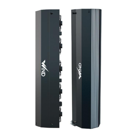
Xvent WiIND Series User manual

1
Verze 1
–
GBR
(
25
.
8
.202
0
)
D
-
502
-
01
71
INSTALLATION AND OPERATING
MANUAL FOR THE WIND AIR CURTAIN
(FOR INDUSTRIAL AND COMMERCIAL USE)

2
Verze 1
–
GBR
(
25
.
8
.202
0
)
D
-
502
-
01
71
CONTENT
1. General information ........................................................................................................................................................................ 4
1.1. Introduction .................................................................................................................................................................... 4
1.2. Use of the unit ................................................................................................................................................................. 4
1.3. Transport, inspection of delivery and storage .................................................................................................................. 4
1.4. Contents of the package .................................................................................................................................................. 5
1.5. Before start of installation ............................................................................................................................................... 5
2. Technical parameters ....................................................................................................................................................................... 5
2.1. WIND air curtain design ................................................................................................................................................... 5
2.1.1. AXIAL EC FANS ................................................................................................................................................................... 5
2.1.2. WATER EXCHANGER .......................................................................................................................................................... 5
2.1.3. CURTAIN CASING ............................................................................................................................................................... 5
2.1.4. EXHAUST LAMELLAS .......................................................................................................................................................... 5
2.2. Main dimensions and requirements for the minimum working space for the WIND curtain ........................................... 6
2.3. Technical data ................................................................................................................................................................. 7
2.4. Technical data of water heaters ...................................................................................................................................... 7
3. Installation – installation of air curtains in the working position .................................................................................................. 8
3.1. General information, recommendations and safety during installation of the Wind air curtain ...................................... 8
3.1.1. Electrical safety when installing the curtain ..................................................................................................................... 8
3.1.2. Modification of existing heating distribution systems ..................................................................................................... 8
3.1.3. Load bearing capacity of the assembly site ...................................................................................................................... 8
3.1.4. Minimum assembly distances ........................................................................................................................................... 8
3.1.5. Minimum safety distance from flammable substances ................................................................................................... 9
3.1.6. Operation environment of the curtain ............................................................................................................................. 9
3.1.7. Levelling of the curtain ...................................................................................................................................................... 9
3.2. Ceiling installations.......................................................................................................................................................... 9
3.2.1. Positioning the curtain in the working position ............................................................................................................... 9
3.2.2. Fixing the curtain to the floor ........................................................................................................................................... 9
3.3. Vertical installation - curtain chaining ........................................................................................................................... 10
3.3.1. Chained curtain mounting .............................................................................................................................................. 10
3.3.2. Side anchoring of the chained assembly ........................................................................................................................ 11
3.3.3. Maximum height of chained curtains ............................................................................................................................. 11
3.4. Vertical installation – increased barrier effect ............................................................................................................... 12
3.5. Horizontal installation ................................................................................................................................................... 12
3.5.1. Preparation for the curtain suspension .......................................................................................................................... 12
3.5.2. Determination of the installation site ............................................................................................................................ 13
3.5.3. Auxiliary anchoring structures ........................................................................................................................................ 13
3.5.4. Correct installation in horizontal position ...................................................................................................................... 13
3.5.4.1. Examples of Curtain Suspension – Horizontal Installation............................................................................................. 14
3.5.5. Measurement of anchoring holes ................................................................................................................................... 14
3.5.6. Installation of the auxiliary anchoring structure ............................................................................................................ 14
3.5.7. Installation – hanging the curtain into the working position ........................................................................................ 14

3
Verze 1
–
GBR
(
25
.
8
.202
0
)
D
-
502
-
01
71
3.6. Horizontal installation - curtain chaining ....................................................................................................................... 15
3.6.1. Installation of the auxiliary anchoring structure ............................................................................................................ 15
3.6.2. Determination of the installation location for the chained curtains ............................................................................. 15
3.6.3. Auxiliary anchoring structures for chained curtains ...................................................................................................... 15
3.6.4. Correct installation in horizontal position during curtain chaining ............................................................................... 15
3.6.4.1. Examples of curtain suspension - horizontal installation – chaining ............................................................................. 17
3.6.5. Measurement of anchoring holes for chained curtains ................................................................................................. 17
3.6.6. Installation – suspension of the chained curtains into the working position................................................................ 17
3.7. Installation – suspension of the chained curtains into the working position .................................................................. 17
3.8. Water exchanger connection ......................................................................................................................................... 18
3.8.1. Connection of the curtain to the hot water distribution system ................................................................................... 18
3.8.2. Water exchanger connection .......................................................................................................................................... 18
3.8.3. Venting (discharge) valve ................................................................................................................................................ 19
3.8.4. Example hydraulic diagram of unit connection .............................................................................................................. 19
3.9. Electrical installation and electrical connection ............................................................................................................. 20
3.9.1. General Information - Safety .......................................................................................................................................... 20
3.9.2. Connection of power supply and curtain control ........................................................................................................... 20
3.9.3. Description of power and control terminals – electrical diagram of motors ................................................................ 21
3.9.3.1. Description of connection of 1 curtain ........................................................................................................................... 21
3.9.3.2. Description of the curtain connection during the chaining ........................................................................................... 21
3.9.4. Connection to the mains ................................................................................................................................................. 22
3.9.5. Display of electrical parameters on the curtain ............................................................................................................. 22
4. Regulation ...................................................................................................................................................................................... 22
4.1. General Information – Safety ........................................................................................................................................ 22
4.2. Control elements ........................................................................................................................................................... 23
5. Atacama heating unit wiring diagram ........................................................................................................................................... 24
5.1. Details of connecting the main terminal box to the regulator ELEMENTAIR-E-M1 and with the accessories .................. 24
5.2. Connection of the Wind curtain with the regulator ELEMENTAIR-E-M1 ......................................................................... 24
5.3. Connection of chained Wind curtains with regulator ELEMENTAIR-E-M1 ...................................................................... 25
6. Commissioning ............................................................................................................................................................................... 26
6.1. Before the first start check the following: ...................................................................................................................... 26
6.2. Switching on .................................................................................................................................................................. 26
7. Regular maintenance and cleaning of the WIND curtain ............................................................................................................. 26
7.1. Regular maintenance ..................................................................................................................................................... 26
7.2. Cleaning procedure........................................................................................................................................................ 26
8. Service ............................................................................................................................................................................................ 27
8.1. Troubleshooting procedure ........................................................................................................................................... 28
9. Decommissioning and recycling .................................................................................................................................................... 28
10. Warranty ................................................................................................................................................................................... 29
11. Conclusion ................................................................................................................................................................................. 29

4
Verze 1
–
GBR
(
25
.
8
.202
0
)
D
-
502
-
01
71
1. General information
1.1. Introduction
- This document "Installation and Operating Manual" is intended for the Wind air curtain (hereinafter the
"curtain"), which is used to separate the interior from the external environment by a stream of air and for
hot-air heating of the required space. Detailed familiarisation with this document is important for the
correct and safe installation and functioning of the curtain. Failure to follow the conditions in this document
may result in malfunction of the unit.
- The curtain may only be installed and connected by a trained person with the appropriate authorization
to connect electrical equipment, which has available suitable tools and means. During the assembly, it is
necessary to observe all the instructions and recommendations in this manual.
- For the correct operation and long-term service life of the unit, it is necessary to prevent access to
unauthorised persons and to train operators according to this document and applicable legislative
regulations.
- The documentation must always be available at the place of installation for any service intervention. It is
forbidden to interfere in any way with the internal connection of the curtain, which does not correspond to
the instructions given in this manual. Due to the continuous development of our products, we reserve the
right to change this manual without prior notice.
1.2. Use of the unit
- The Wind air curtain is designed to separate the interior from the environment by a stream of air. This
prevents the internal air from leaking out of the internal environment to the external environment when
the doors, gates, etc...are open. Other function of the curtain when the doors or gates are closed is to heat
the internal space by hot-air heating. When purchasing accessories – filter, the curtain also serves to filter
the air in the inner environment.
- The curtain is intended mainly for entrances to industrial halls, warehouses, sports facilities, workshops,
smaller facilities and commercial premises.
- The curtain is designed for indoor covered and dry areas with ambient temperatures between 5°C and
+40°C.
- The curtain may also be used for environments with a higher non-condensing humidity corresponding to
the protection class IP54 and IP44 according to EN 60529, depending on the type of curtain. However, the
maximum allowed humidity is 80%. The curtain may also be used in corrosive environment C2 according to
EN ISO 9223. The curtain must not be operated in an environment with the risk of explosion and increased
dustiness.
- Neither the manufacturer nor the supplier is liable for damage caused by improper use of the curtain. The
risk is borne by the user alone.
- The curtain must not be operated during finishing construction activities, especially during activities that
create excessive dustiness, e.g. by grinding concrete, plasterboard, etc...
1.3. Transport, inspection of delivery and storage
- Before starting the installation and before unpacking the unit from the box, it is necessary to check for any
traces of damage on the packaging. In case of damage to the packaging, please contact your carrier.
- Check if the product ordered by you is in agreement. After unpacking, check that the unit and other
components are intact. Please report any non-conformity with the order to the supplier immediately.
If an order complaint is not made immediately after delivery, it will not be taken into account later.
- If you do not install the unit immediately after purchase, it must be stored in an indoor, non-
condensing environment at temperatures in the range of 5 to 40°C. If the product has been
transported at temperatures below 5°C, it must be stored after unpacking for at least 2 hours in the
working environment where it will be installed.
- Use adequate tools to prevent damage to the goods and to avoid health and safety risks of persons.

5
Verze 1
–
GBR
(
25
.
8
.202
0
)
D
-
502
-
01
71
1.4. Contents of the package
WIND 1 air curtain 1x
Quick manual + Safety Data Sheet 1x
Name plate 1x
1.5. Before start of installation
- Before starting the installation, we recommend that you attach the serial nameplate (normally delivered
with the unit in its package) to the operational documentation (e.g.: equipment operating book, etc.),
which is subsequently kept for a later maintenance record and the respective servicing.
- Before starting all installation or maintenance work, it is necessary to switch off the power supply and
secure the switch against switching it on again.
2. Technical parameters
2.1. WIND air curtain design
2.1.1. AXIAL EC FANS
The maximum operating temperature of the fan motor is + 60°C, operating humidity 0-90% non-condensing,
protection class IP54 and IP44 according to the selected curtain type, and the motor insulation class B. The fan and
its board are treated with powder coating RAL 9005.
2.1.2. WATER EXCHANGER
Maximum permissible temperature/pressure of heating medium 120°C / 1.6MPa. The exchanger consists of
an aluminium - copper structure. Water exchanger is connected by connectors with mail thread 1". The
exchanger is equipped with a venting valve on both collectors.
2.1.3. CURTAIN CASING
The sheet metal casing of the curtain consists of two parts. The rear part towards the fan is in RAL 9005
colour. The front part towards the exhaust lamellas is in RAL 7016 colour.
2.1.4. EXHAUST LAMELLAS
The exhaust lamellas are designed from aluminum profiles, which are provided against corrosion and
mechanical damage by "anodizing" (artificial corundum). They are not used to deflect the air stream. The air
flow redirection is tackled in Chapter 3.7.
EXHAUST
LAMELLAS
WATER
EXCHANGER
AXIAL EC
FAN
ELECTRICAL
JUNCTION BOXES
CURTAIN
COVER

6
Verze 1
–
GBR
(
25
.
8
.202
0
)
D
-
502
-
01
71
2.2. Main dimensions and requirements for the minimum working space for the WIND curtain
VERTICAL INSTALLATION
HORIZONTAL INSTALLATION
MIN. OPERATING AND INSTALLATION SPACE

7
Verze 1
–
GBR
(
25
.
8
.202
0
)
D
-
502
-
01
71
2.3. Technical data
EC Declaration of Conformity – the current and full version of the EC Declaration of Conformity can be seen on our website
www.xvent.cz under the Wind (category „hot air heating“) product documents
2.4. Technical data of water heaters

8
Verze 1
–
GBR
(
25
.
8
.202
0
)
D
-
502
-
01
71
- other technical parameters can be found in the catalogue sheet
3. Installation – installation of air curtains in the working position
3.1. General information, recommendations and safety during installation of the Wind air curtain
3.1.1. Electrical safety when installing the curtain
- Before starting any assembly works, it is necessary to switch off the power supply to the prepared
electrical installation for subsequent activation of the unit. During installation, the switch must be
secured against being switched on again.
3.1.2. Modification of existing heating distribution systems
- It is appropriate to use filters for rough impurities in the heating systems to protect the water exchanger
from possible damage from the existing distribution systems.
3.1.3. Load bearing capacity of the assembly site
- The selected assembly site must be suitable for the permanent load by the curtain. In case of doubt, the
load capacity of the wall/walls must be verified by a structural engineer or other responsible person.
3.1.4. Minimum assembly distances
- The minimum intake distance (fan) of the curtain from the wall/ceiling is 0.3 m.
- The minimum distance between the side of the curtain and the wall is 0.1 m (assess a suitable distance
from the side of the exchanger outlets to allow easy connection).

9
Verze 1
–
GBR
(
25
.
8
.202
0
)
D
-
502
-
01
71
- If this distance is not observed, the curtain may not work properly and the fans may be damaged or the
noise of the unit may increase. The curtain exhaust must be set in such direction that there is no draft in
the heated space, and, at the same time, for the best separation of spaces – to shield the inner space from
the external influence. The air flow exiting the exhaust grid must not be directed directly to walls, beams,
shelves, machines, etc.
3.1.5. Minimum safety distance from flammable substances
- The minimum safety distance from flammable substances is at least 0.1 m from the side of the curtain
(assess a suitable distance from the outlet of the exchangers due to easy connection) and 0.5 m in the
direction of suction of the curtain. Adjust the distances according to the layout of the space.
3.1.6. Operation environment of the curtain
- The curtain must be located / operated in an inner dry space with temperatures range from 5°C to +40°C
(the conditions must avoid water freezing in the exchanger – there is a risk of damage to the curtain) and
non-condensing humidity corresponding to protection class IP 54 and IP 44, according to the selected type
of curtain.
3.1.7. Levelling of the curtain
- The curtain must be always levelled – with spirit level in the appropriate plane in which it is operated!
3.2. Ceiling installations
- The curtain must stand on a flat, coherent and solid surface.
- The correct height of the curtain must be at least 100 mm longer than the actual height of the curtained
hole. If the height of the opening is greater than or equal to the height of the curtain, you must attach an
additional curtain, see Point 3.3.
3.2.1. Positioning the curtain in the working position
- Place the unpacked curtain in its working position.
- Place it close to the hole that should be curtained in such a way that:
o The edge of the exhaust curtain closer to the wall must be flush with the door frame hole, at a
minimum distance from the wall (see paragraphs 3.1.4. and 3.1.5.)
o Turn the curtain at 10° with the exhaust pointing out.
Curtain pre-blow setting - important for correct operation of the curtain
3.2.2. Fixing the curtain to the floor
- The curtain is fixed to the floor using the "WIND-HOLDER" (must be ordered as accessories).
- Screw the holder to the curtain with 6 screws M6x20 (a part of the packing of the “WIND-HOLDER”).
- Mark the center of the drilled holes in the four grooves for anchoring to the floor. The centre of the drilled
holes must be in the end positions of the anchoring grooves, for the possibility of increasing the curtain pre-
blow (even greater turning of the curtain out). The holder installed in this way allows an increase of the pre-
blow by up to 20°, i.e. the curtain may be rotated from 10° to 30°.
- Select suitable anchoring material and tools according to the floor material and type. Anchoring material is
not part of the delivery.

10
Verze 1
–
GBR
(
25
.
8
.202
0
)
D
-
502
-
01
71
POSSIBILITY OF ROTATION UP TO 20 °
- The diameter of the anchoring material (clamps, bolts into dowels) must be 10 mm. A washer shall be
placed under the head of the anchoring screws/nuts to better distribute the curtain weight.
- Screw the holder into the floor in such a way that the anchoring screws are in the end positions of the
anchoring grooves for the subsequent possibility of increasing the pre-blow of the curtain. The curtain
should be automatically rotated 10° outwards. Final fine-tuning – the curtain rotation is dealt with in point
3.7.
- Tighten the holder to the floor.
3.3. Vertical installation - curtain chaining
- Chaining – connecting the curtains to one another makes it possible to create an ideal assembly for proper
clearance of the required opening according to its dimensions.
- The correct height of the chained assembly must be at least by 100 mm longer than the actual height of the
construction opening.
- The curtains are chained on each other using the "WIND-CONNECT" connecting piece (it is necessary to order
the pieces as accessories).
3.3.1. Chained curtain mounting
- Install the "WIND-CONNECT" connection piece onto the top of the anchored curtain, so that 1/2 of the
connection piece projects over the anchored curtain. Use 6 screws M6x20 (part of the connecting piece
packing) to install the connection part.
- Lift up the curtain to be connected to the lower anchored curtain with appropriate lifting devices.
- Ensure compliance with all safety principles resulting from handling the curtain to prevent any damage to
the property and health of persons.
- Insert the curtain into the prepared /mounted connection piece and secure with 6 screws M6x20 (part of the
fitting package).

11
Verze 1
–
GBR
(
25
.
8
.202
0
)
D
-
502
-
01
71
Use recommended accessories (WIND-
CONNECT) to connect the curtain in
case of chaining
Anchoring to the floor using a
rotating holder (WIND-HOLDER) -
not included in the packaging.
Screwing in by using a suitable
connecting material.
3.3.2. Side anchoring of the chained assembly
- When chaining multiple curtains, each subsequent curtain must be additionally anchored from the side to
maintain the stability of the entire assembly.
- The side anchorage shall be made at the highest point of the chained assembly.
- Use the nuts M6 located at the side and at the curtain rear part (by the fan) to anchor the assembly from the
side.
- Select a suitable method and connecting material for anchoring according to the situation at the place of
installation
3.3.3. Maximum height of chained curtains
- The maximum height of the chained
assembly must not be greater than 6.5
m.
- If the height of the assembly is higher
than 6.5 m, it is necessary to select a
method that creates a separate
supporting element for supporting the
subsequent curtains. The supporting
element must be suitable to avoid
loading of the lower-chained assembly
by the top assembly so that it cannot be
damaged or even cause damage to a
property or endanger the health of
persons.
The maximum height of the chained
curtains is 6.5 m + necessary anchoring
during the curtain chaining

12
Verze 1
–
GBR
(
25
.
8
.202
0
)
D
-
502
-
01
71
3.4. Vertical installation – increased barrier effect
- To increase the barrier effect, the curtain can be installed on both sides of the curtained opening (e.g.
permanently open gates for loading and unloading trains)
- The curtains shall be installed in accordance with the same procedure as described in points 3.2 and 3.3.
3.5. Horizontal installation
- The surface (e.g. wall, brickwork) and auxiliary structures necessary to anchor the curtain must have an
adequate load capacity based on the weight of the selected curtain type. Neither the anchoring material
nor the auxiliary structures are provided by the supplier. The owner provides for himself/herself according
to local conditions. See paragraph 3.5.2 for examples of installation.
- For the correct functionality of the curtain (curtaining the opening), the curtain must overlap on each side
by at least 100 mm beyond the width of the curtained opening. If the width of the opening is greater than or
equal to the length of the curtain, you should attach an additional curtain, see Point 3.6.
3.5.1. Preparation for the curtain suspension
- Unpack the curtain from the top of the curtain only (the curtain is delivered in the horizontal position), and
proceed as follows:
o remove wooden battens,
o remove plastic packaging and tapes.
SELECT THE
CURTAIN
ACCORDING TO THE WIDTH OF THE DOOR OPENING,
DEPENDING ON THE ACTIVE BLOWING DISTANCE (AVAILABLE IN THE TECHNICAL
DATA)
IN CASE OF OPENING WIDTH MORE THAN 8 M, WE RECOMMEND
INSTALLING THE CURTAINS ON BOTH SIDES OF THE DOOR OPENING
THE MAXIMUM HEIGHT OF THE CHAINED
CURTAIN
S IS 6.5 m
FOR CORRECT DOOR
CURTAINING, IT IS NECESSARY TO
OBSERVE OVERLAPPING OF THE
WIND CURTAIN BY ABOUT 50-
100mm

13
Verze 1
–
GBR
(
25
.
8
.202
0
)
D
-
502
-
01
71
3.5.2. Determination of the installation site
- Determine the place for curtain installation; exhaust of the curtain must be flush with the door frame opening
at the minimum distance from the wall (see 3.1.4. and 3.1.5.). If this is not possible, the general rule for
correct positioning and subsequent turning of the curtain (pre-blow setting) applies, i.e. the exhaust corner
of the curtain must always be at the tangent of the shielded opening. See paragraph 3.7 for further
explanations.
3.5.3. Auxiliary anchoring structures
- Prepare suitable auxiliary anchoring structures (consoles, threaded rods, etc.) depending on the weight of
the curtain, the surface into which you will anchor, and the selected suspension method (into the ceiling, in
the wall, etc.).
- Wind air curtain weight table:
3.5.4. Correct installation in horizontal position
- To allow proper rotation of the curtain - 10° towards the outside area (pre-exhaust setting) - the total
length of the hinge from the wall, on the far side of the wall, must be longer by 90 mm. The expected
lateral distance of the curtain from the wall is 100 mm.
- If the distance from the wall is larger, the curtain must rotate at a larger angle, and the hinge length must
be recalculated.
- To correctly determine the rotation angle of the curtain, the rule must be observed that the corner of the
curtain exhaust must always be tangentially to the shielded opening.
- To facilitate suspension, we recommend using simple hangers (WIND-HINGE accessories), which are attached
to the prepared threaded nuts on the side of the unit (use M6x20 screws).
USE OF ASSEMBLY HINGES (ON EACH CURTAIN USE
4
HINGES) - WIND-HINGE accessories
THREADED RODS
DOOR OPENING

14
Verze 1
–
GBR
(
25
.
8
.202
0
)
D
-
502
-
01
71
- Installation on the wall using the wall
console and threaded rods M8-10. Consoles
and M8-10 threaded rods are not included in
the delivery. It is ensured by the user
according to local conditions.
3.5.4.1. Examples of Curtain Suspension – Horizontal Installation
3.5.5. Measurement of anchoring holes
- Measure the anchoring holes according to the selected curtain type and anchoring type (according to the
suspension layout) - see the main dimensions 2.2 - dimension D.
3.5.6. Installation of the auxiliary anchoring structure
- Install auxiliary anchoring structures, e.g.: wall consoles. Select suitable anchoring material and tools
according to the material and the type of the background. Anchoring material is not part of the delivery.
3.5.7. Installation – hanging the curtain into the working position
- Lift the partially unpacked curtain according to section 3.5.1. with the installation hinges, using a suitable
handling technique (e.g. a lift truck) to the prepared assembly point. Partial packaging (pallet, protective
polystyrene) is used to protect the product from damage by scratching.
THREADED RODS
DOOR OPENING
THREADED RODS
DOOR OPENING
AUXILIARY CONSOLE
- Installation on the ceiling using the M8-10
threaded rods. Threaded rods M8-10 are
not included in the delivery. It is ensured
by the user according to local conditions.

15
Verze 1
–
GBR
(
25
.
8
.202
0
)
D
-
502
-
01
71
- When handling the curtain, take into account its weight and ensure that all safety principles are observed
so that no damage to the property or health of persons occurs.
- Secure the screw connections with the nuts against spontaneous unscrewing and subsequent fall.
3.6. Horizontal installation - curtain chaining
- The curtains to be chained must not be connected before lifting them to the working position . Always
handle only one curtain at a time, intended for chaining. The curtains will be connected to one another
only after anchoring to the wall or the ceiling.
- By chaining – connecting the curtains side by side, it is possible to create an ideal assembly for proper
curtaining of the particular opening, according to its dimensions.
- The correct length of the chained assembly must be at least by 100 mm longer from each side than the actual
length of the curtained opening.
- The curtains are chained next to each other using the "WIND-CONNECT" connecting piece (it is necessary to
order the pieces as accessories).
- The length of the chained curtain is not limited when installing the curtain in the horizontal plane.
3.6.1. Installation of the auxiliary anchoring structure
- Preparation for the curtain suspension according to section 3.5.1.
3.6.2. Determination of the installation location for the chained curtains
- Determine the place for the installation of the chained curtain; the exhaust curtain must be flush with the
frame opening at the minimum distance from the wall (see 3.1.4. and 3.1.5.).
- When chaining the curtains, consider sufficient room for handling in the installation area.
3.6.3. Auxiliary anchoring structures for chained curtains
- Complete the auxiliary anchoring structure according to section 3.5.3. with respect to the weight of the
chained assembly.
- 2 pcs of auxiliary anchoring structures per 1 piece of curtain must always be used (e.g.: 3 pieces of curtains
in a chain - there must be 6 pieces of auxiliary anchor structures).
3.6.4. Correct installation in horizontal position during curtain chaining
- For proper rotation of the curtain, i.e. 10° towards the outside area (blowing distance adjustment), the
total length of the hinge at the more distant side must be 90 mm from the wall. The expected lateral
distance of the curtain from the wall is 100 mm.
- If the distance from the wall is larger, the curtain must rotate at a larger angle, and the hinge length must
be recalculated.
- To correctly determine the rotation angle of the curtain, the rule must be observed that the corner of the
curtain exhaust must always be tangentially to the shielded opening.
USE OF ASSEMBLY HINGES (ON EACH CURTAIN USE
4
HINGES) - WIND-HINGE accessories
THREADED RODS
DOOR OPENING

16
Verze 1
–
GBR
(
25
.
8
.202
0
)
D
-
502
-
01
71
- To facilitate suspension, we recommend using simple hinges (WIND-HINGE accessories), which are
attached to the prepared threaded nuts on the side of the curtain (use M6x20 screws). Use it also in case of
mounting via "WIND-CONNECT" connecting piece
- Install the "WIND-CONNECT" connecting piece onto the side of the first
chained curtain, so that 1/2 of the connecting piece protrudes from the
chained curtain. Use 6 screws M6x20 (part of the connecting part
packing) to install the connection piece.
- Chained curtains must not be connected before lifting them to the
working position. Always handle only one curtain at a time, intended
for chaining. The curtains will be connected only after anchoring it to
the wall or the ceiling.
ASSEMBLY ILLUSTRATION - CHAINING OF CURTAINS + DISTANCE CONDITIONS
FOR CORRECT DOOR
CURTAIN
ING, IT IS NECESSARY TO OBSERVE
OVERLAPPING OF THE WIND CURTAIN BY ABOUT 50-100mm
THE MAXIMUM HEIGHT DOOR OPENING IS 8m

17
Verze 1
–
GBR
(
25
.
8
.202
0
)
D
-
502
-
01
71
- Installation on the wall using the wall
console and threaded rods M8-10. Consoles
and M8-10 threaded rods are not included in
the delivery. It is ensured by the user
according to local conditions.
3.6.4.1. Examples of curtain suspension - horizontal installation – chaining
3.6.5. Measurement of anchoring holes for chained curtains
- Measure the anchoring holes according to the selected type of chained curtains and anchoring type
(according to the placement of hinges) - see the main dimensions 2.2 - dimension D
3.6.6. Installation – suspension of the chained curtains into the working position
- Lift the partially unpacked curtain according to section 3.5.1. with mounted mounting hinges using a suitable
handling technique (e.g. forklift) to the prepared assembly point. Partial packaging (pallet, protective
polystyrene) is used to protect the product from damage by scratching. Then continue in chaining according
to the instructions, see 3.6.4
3.7. Installation – suspension of the chained curtains into the working position
- Measure the anchoring holes according to the selected type of chained curtains and anchoring type
(according to the suspension layout) - see the main dimensions 2.2 - dimension D
THREADED RODS
DOOR OPENING
THREADED RODS
DOOR OPENING
AUXILIARY CONSOLE
- Installation on the ceiling using the M8-10
threaded rods. Threaded rods M8-10 are
not included in the delivery. It is ensured
by the user according to local conditions.

18
Verze 1
–
GBR
(
25
.
8
.202
0
)
D
-
502
-
01
71
POSSIBILITY OF
ROTATION UP TO 20 °
- Setting the correct curtain pre-blow is the basic prerequisite for proper separation between the interior
and the outer space.
- At the curtain, the pre-blow is adjusted by turning the entire curtain. Pre-blowing adjustment using the
lamellas is not possible.
- Minimum – the basic pre-blow angle is 10°.
3.8. Water exchanger connection
3.8.1. Connection of the curtain to the hot water distribution system
- connect the curtain to the heating system using a flexible connecting piece with diameter 1" (e.g. Flexo hose
with braiding – armoured hose). The flexible connection must be long enough to allow the pre-blow to be
adjusted after commissioning.
3.8.2. Water exchanger connection
- Water supply and drainage necks are marked on the water exchanger collectors. To tighten the connected
piping to the curtain, use the hexagonal profile on the water exchanger necks. This prevents the exchanger
outlet from being overturned, which may result in irreversible damage to the water exchanger.
- Curtain rotation – increase of pre-
blow at a vertical installation allows
the installed stand to be mounted
within the range of 0 to 20°, so the
maximum angle of the curtain
turning towards the opening
(direction out) is 30°.
3.7.1 Curtain rotation – vertical
installation
3.7.2 Curtain rotation – horizontal
installation
- The curtain rotation – it is possible
to increase the pre-blowing of the
horizontal installation by
unscrewing or extending the
threaded bars on the brackets.
THREADED RODS
DOOR OPENING
- After connecting the water exchanger to the heating system, a pressure
test of the connected curtain is recommended.
- The tests must be carried out by a person qualified in this field with
knowledge of the applicable regulations and standards of the country
concerned.
- We recommend installing shut-off valves on the water exchanger inlet
and outlet for the shut-off of the heating medium, or to allow the
curtain dis-assembly without the need to drain water from the heating
system.

19
Verze 1
–
GBR
(
25
.
8
.202
0
)
D
-
502
-
01
71
3.8.3. Venting (discharge) valve
- Water exchangers are fitted with venting screws on the inlet and drainage collectors.
- Venting of the exchanger is done by loosening the vent screw.
3.8.4. Example hydraulic diagram of unit connection
- If the automatic control valve is not installed to control the heating capacity, we recommend to shut off the
heating water supply to the exchanger when the fan is switched off. Any high temperature inside the unit on
the exchanger may reduce the fan lifespan.
Legend:
1. Wind
2. speed regulator with thermostat
3. vent valve - part of the exchanger
4. flexible hose
5. shut-off valve
6. 2-way valve with thermoelectric drive
7. filter
8. pump
9. source of hot water

20
Verze 1
–
GBR
(
25
.
8
.202
0
)
D
-
502
-
01
71
3.9. Electrical installation and electrical connection
3.9.1. General Information - Safety
- The relevant electrical installation and electrical assembly of the units may only be performed by persons
qualified for this activity with valid authorization and knowledge of the applicable standards and
directives. Before starting any assembly works, it is necessary to switch off the power supply to the
prepared electrical installation for subsequent activation of the unit. During installation, the switch must
be secured against being switched on again by an unauthorized person.
- The curtain shall be connected to the main power supply by the TN-S system (neutral wire connected)
using an insulated cable in accordance with the diameter and corresponding regulations.
- The electrical installation and connection must be carried out on the basis of the electrical project
proposed by a professional designer.
- Electrical diagrams on the product have higher priority than the diagrams in this manual!
- The supply voltage of the curtain shall be connected in such a way that all poles of the network are
disconnected from the power supply by one element (e.g. main switch). The unit inlet phase must be
connected via a protective power circuit breaker (protective switch) according to the corresponding
current. The minimum distance between the disconnected contacts must be greater than 3mm.
- Before installation, check that the cable marking corresponds to the electrical diagram. If you have any
doubts, please contact your supplier.
3.9.2. Connection of power supply and curtain control
- The curtain is equipped with a wiring box containing spring terminals of the push-in type for connecting the
curtain power supply and control, membrane bushings for pulling the control cable through and a threaded
bushing for connecting the curtain power supply (this bushing is intended only for the power supply cable).
- For correct installation of the curtain power cable, choose a free opening in the electrical installation box,
into which screw the M20x1.5 threaded plastic bushing (part of the delivery).
o First, screw in the bushing slightly with your hand
o After the resistance of bushing against turning has increased, use a flat wrench size 24
o The bushing itself cuts through the opening in the wiring box, pushing out the cut-out section of the
box (a wheel)
- The bushing can accommodate cables with diameters 6 to 13 mm.
- Pull the supply cable through the installed bushing and tighten it with a flat wrench size 24.
- The correct installation of the bushing and its correct tightening also serve as a protection against pulling
and tearing of the power cable
- Use the remaining membrane bushings at your discretion to install the control cable correctly.
o Pierce the bushing membrane with a screwdriver
o Pull through the control cable
- Strip the cable insulation to a minimum length of 90 mm
- Strip the individual wires in the length of 10 mm. In the case of strand-type conductors, an insulated end
piece must be pressed on (tube)
- Spring terminals are equipped with manual locking of wires. Strand-type conductors provided with pressed
end (tube) may be installed in the terminals as well as solid conductors (wire) with cross section range from
0.2 to 1.5 mm². To connect the wire to the terminals, press the wire with a reasonable force and then slightly
pull back to ensure that the wire is properly secured.
This manual suits for next models
3
Table of contents
Other Xvent Heater manuals
Popular Heater manuals by other brands

Toyotomi
Toyotomi Kero Sun Omni 120 (Type C) Operation and maintenance instructions

Webasto
Webasto Air Top 2000 STC Workshop manual

AEG
AEG VH 206 Operating and installation instructions

LVI
LVI YALI PARADA Installation and operating manual

Rowi
Rowi HHL 2000/3/1 Flat operating instructions

S&P
S&P EC-3N User instructions