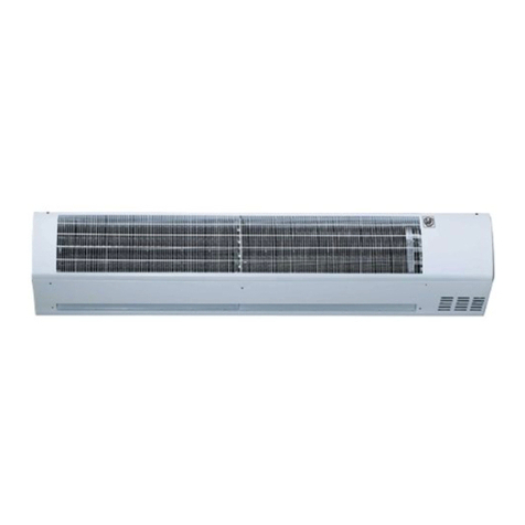
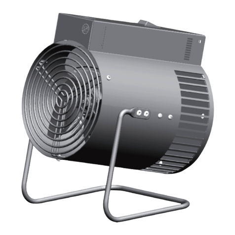
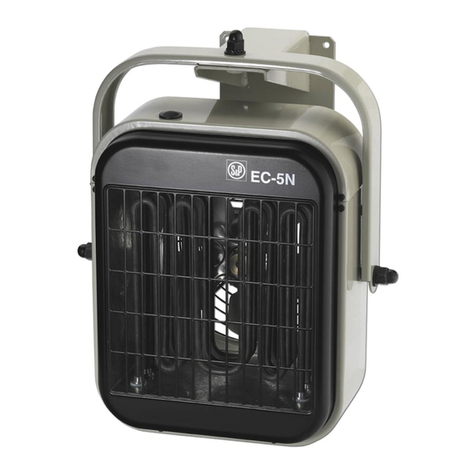
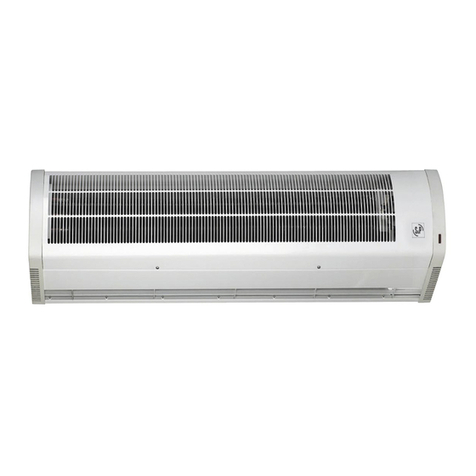
S&P EC-3N User manual

EC-3N
EC-5N
EC-9N
EC-12N
EC-15N
User Instructions
Notice d’utilisation
Pol. Industrial Llevant
c/ Llevant 4
08150 Parets del Vallès (Barcelona)
ESPAÑA
Tel. 93 571 93 00
http://www.solerpalau.com
Ref. 287965016


Fig.1 Fig.2
Fig.3 Fig.4
wcisnieciu urzadzenie powinno normalnie
pracowac. W przypadku jesli nastapi
ponowne zadzialanie zabezpieczenia,
oznacza to, ze termowentylator nie dziala
prawidlowo, zatem nalezy odlaczyc je od
zasilania i skontaktowac sie z
autoryzowanym serwisem dostawcy.
KONSERWACJA
UWAGA: PRZED PRZYSTAPIENIEM DO
PRAC KONSERWACYJNYCH NALEZY
UPEWNIC SIE, ZE URZADZENIE JEST
ODLACZONE OD SIECI ZASILAJACEJ.
Aby zapewnic dluga i bezawaryjna prace
urzadzenia zaleca sie regularne
sprawdzanie i czyszczenie wlotu i wylotu
powietrza z pylu i kurzu (przynajmniej raz
w kazdym sezonie). Operacja ta powinna
byc wykonywana przez wykwalifikowanego
technika.
Nalezy regularnie czyscic siatki na wlocie i
wylocie urzadzenia.
Nie wolno zanurzac urzadzenia w zadnych
plynach ani ustawiac pod kranem.
Demontaz urzadzenia w okresie
obowiazywanie gwarancji spowoduje jej
utrate.
Wewnetrzny wylacznik róznicowy
zabezpieczajacy urzadzenie moze
powodowac czasami samoczynne
wylaczenie sie termowentylatora. Jest to
normalna procedura w przypadku
obecnosci produktów kondensacji wilgoci
na elementach grzalek. Elementy te moga
kumulowac w swoim wnetrzu wilgoc, jesli
urzadzenie nie pracuje przez dluzszy czas.
Nie powinno byc to traktowane jako defekt.
Aby przywrócic wlasciwe funkcjonowanie
urzadzenia, nalezy podlaczyc
termowentylator do sieci z pominieciem
wylacznika róznicowego. Rozpocznie sie
okres suszenia urzadzenia, który moze
potrwac kilka godzin lub nawet dni. Aby
uniknac tego typu sytuacji zaleca sie
uzywanie termowentylator periodycznie.
UWAGA: Czyszczenie i przeglad urzadzenia
nalezy przeprowadzac przynajmniej raz do
roku (bez wzgledu na to czy urzadzenie w
tym okresie pracowalo czy tez nie),
dzialanie to zapewni jego bezawaryjna
prace.
NORMY: Wszystkie modele sa zgodne z
wymaganiami europejskich norm
dotyczacymi kompatybilnosci
elektromagnetycznej i zaklócen.
SERWIS.
Jesli w trakcie okresu gwarancyjnego
nastapi usterka urzadzenia prosimy
skontaktowac sie z punktem sprzedazy lub
bezposrednio z serwisem producenta.
UWAGA: Próby samodzielnej naprawy
spowoduja utrate gwarancji.
Soler & Palau zastrzega sobie prawo do
zmian w niniejszej publikacji bez
wczesniejszego powiadomienia.
·
˛
´˛
´´˛
´
·´
´·´˛´
´˛
˛·
´˛·˛
´˛˛
´´˛˛
˛˛
´
·
´
·´´
˛´˛·
´´
·˛
˛
˛
˛´˛
˛˛ ·
´
´˛˛
´´˛
´˛´´
˛´·
´
´´
´
˛·´˛´
˛
´·˛
˛·
´
˛´˛
·
˛˛
·´
˛˛
´·
´˛
˛
˛
˛´
´
´
´˛˛
´˛·
´
˛˛
´

Fig.5 Fig.6
Fig.7
W celu podlaczenia nalezy postepowac tak
samo jak w przypadku podlaczania
przelacznika CR-25 (powyzej).
Podlaczenie elektryczne nalezy wykonac
zgodnie z diagramem danego termostatu
(TR-1 lub TR-2).
Termostat typu TR-1 moze byc stosowany
z modelami termowentylatorów EC-3N, EC-
5N i EC-9N.
Termostat typu TR-2 moze byc stosowany
z modelami termowentylatorów EC-12N i
EC-15N. Zastosowanie termostatu pozwala
na róznicowanie temperatur oraz
oszczednosc energii.
OBSLUGA
Przelacznik CR-25 dziala w sposób opisany
ponizej.
Kolejne pozycje przelacznika sa
nastepujace:
[0] – wylaczenie
[ ] – tylko wentylator
[ ] – wentylator + polowa
mocy nagrzewnicy
[ ] – wentylator + pelna moc
nagrzewnicy
Kiedy przelacznik znajdujacy sie w tylnej
czesci termowentylatora (rys. 6) jest
ustawiony w pozycji ..... opcjonalny
termostat (TR-1 lub TR-2) reguluje prace
jedynie nagrzewnicy wylaczajac ja po
osiagnieciu nastawionej temperatury. W tej
pozycji wylacznika wentylator stale pracuje.
Natomiast kiedy przelacznik jest w pozycji
....., termostat steruje zarówno praca
wentylatora jak i nagrzewnicy: wylaczenie
wentylatora i nagrzewnicy nastepuje po
osiagnieciu nastawionej temperatury.
Aby nastawic wymagana temperature na
termostacie nalezy:
1. Przed dokonaniem polaczen
elektrycznych sprawdzic, czy
parametry elektryczne sieci zasilajacej
odpowiadaja danym na tabliczce
znamionowej urzadzenia.
2. Nastawic termostat na maksymalna
wartosc temperatury.
3. Ustawic obrotowy przelacznik pracy
wentylatora i nagrzewnicy w
wymaganej pozycji. Uruchomi to
urzadzenie.
4. Po zalaczeniu urzadzenia temperatu-
ra otoczenia zacznie wzrastac. Kiedy
temperatura otoczenia osiagnie
wartosc zadana, nalezy przekrecic
pokretlo termostatu przeciwnie do
ruchu wskazówek zegara, do
momentu az uslyszymy klikniecie.
Urzadzenie zostanie wylaczone. Kiedy
termostat jest w tej pozycji urzadzenie
bedzie sie automatycznie wlaczac i
wylaczac w celu utrzymania stalej,
nastawionej wartosci temperatury
otoczenia.
5. W celu wylaczenia urzadzenia nalezy
przekrecic obrotowy przelacznik do
pozycji (0).
Uwaga: Obudowa urzadzenia jest goraca
podczas jego funkcjonowania.
AUTOMATYCZNE ZABEZPIECZENIE
PRZED PRZEGRZANIEM
Wszystkie urzadzenia wyposazone sa w
wewnetrzne zabezpieczenie przed skutkami
przegrzania. Element ten wylaczy
nagrzewanie w przypadku przegrzania
urzadzenia. Kiedy to nastapi, ponowne
zalaczenie urzadzenie moze miec miejsce
po uplywie minimum 15 minut lub po
dostatecznym schlodzeniu urzadzenia. W
przypadku wylaczenia urzadzenia przez
zabezpieczenie przeciazeniowe nalezy
wykryc przyczyne awarii. Zabezpieczenie to
nalezy zresetowac recznie. W celu
zresetowania zabezpieczenia nalezy po
prostu wcisnac przycisk RESET znajdujacy
sie w na górnej pokrywie urzadzenia. Po
˛
´
˛
·˛´
´˛
´˛
·
´
˛
·´
·´
·´
·
˛´´
´
´˛´
·
´˛˛
˛˛
´
´
´
´˛˛
˛´
˛
´˛˛˛
˛˛
´´˛˛
´˛
˛
˛˛´˛˛
·
´˛´
´
˛
˛
˛
´˛
´´
´´˛
˛´˛˛
´
´´˛
·˛˛·˛´
˛´
·´˛
˛´˛
˛
˛˛ ´˛´
´
´˛´
´
´˛˛ ·
˛´´˛
˛˛
˛·˛
˛
˛
´
˛˛
´˛˛·´
´´˛
´˛˛
˛··
´˛
·´˛·
˛´˛
˛˛

HANGING (CEILING MOUNTED)
AEROHEATERS
Carefully read the following instructions
before using the apparatus.
The EC N range of Aeroheaters comply with
the European safety regulations
It is recommended that on receiving the
apparatus it is checked for defects and
correct operation. Any defects from origin
are covered by the guarantee.
SAFETY RECOMMENDATIONS
-The installation should be carried out
by a qualified electrician
-All installation work should be carried
out in accordance with all applicable
existing national and local regulations
covering electrical installations.
-Do not locate the cable in front of the
air outlet nor in contact with the walls
of the Aeroheater during function.
-Do not place flammable objects within
at least 50cm of the hot air stream.
-Do not cover the Aeroheater with
objects that may restrict the free flow
of air. If the airflow is restricted this
may lead to overheating.
-Ensure that both the air inlet and outlet
grilles are clean and free from
obstructions.
-Do not touch the apparatus with wet
hands.
-If the apparatus is installed in a
bathroom, it should be installed in
such a way that the switches or other
controls are not accessible to anyone
bathing or having a shower.
IMPORTANT SAFETY INFORMATION
ALL S&P AEROHEATERS ARE CERTIFIED
FOR INSTALLATION IN HUMID
ATMOSPHERES.
BEFORE INSTALLATION CHECK THAT THE
MAINS ELECTRICAL VOLTAGE AND
FREQUENCY COINCIDES WITH THE
VOLTAGE SHOWN ON THE PRODUCT
DATA PLATE.
THE MAINS ELECTRICITY SUPPLY
SHOULD BE EARTHED. DO NOT USE
ADAPTERS OR MULTIPLE SOCKETS.
THE APPLIANCE SHOULD BE CONNECTED
TO THE MAINS ELECTRICAL SUPPLY
WITH CORRECTLY SIZED CABLES AND
SHOULD INCLUDE A DOUBLE POLE SWIT-
CH WITH A CONTACT CLEARANCE OF AT
LEAST 3MM.
IMPORTANT
The apparatus should have sufficient space
around it for the circulation of air (fig.1)
The minimum distance between the
Aeroheater and the floor should be a
minimum of 1.8m.
INSTALLATION
The minimum distances in fig.1 should be
observed.
The unit should be fitted to a fixed surface
suitable for this type of installation.
For installation the sequence below should
be followed:
1- Using the support as a guide, mark
the position of the holes in the wall/
ceiling and use the appropriate raw-
plugs for the type of wall/ceiling. Fix
the support using screws. (fig.2)
2- Hang and fix the apparatus from the
support. (fig.3)
ELECTRICAL CONNECTION
All S&P Aeroheaters are designed for
permanent connection to the electrical
supply. When connecting to the mains
supply, follow the directives for low voltage
Prípojka musí byt vybavena vypínacem,
ktery umozní úplné odpojení od
elektrické síte.
Pri pripojování nejdríve sejmete horní
kryt (obr.4). Schéma elektrického
zapojení je pod tímto krytem. Pred
pripojením overte, zda parametry síte
odpovídají stítkovym hodnotám prístroje.
Pouzívejte izolované vodice stejného
prurezu a poctu dle schématu uvedeného
na príslusném modelu ohrívace.
Pripojení k elektrické síti se provede
chránenym kabelem vedenym kabelovou
pruchodkou, jez je soucástí prístroje.
PRIPOJENÍ K EXTERNÍMU OVLADACI
(CR-25)
Prístroj pripojte k elektrické síti pres
externí ovladac CR-25, ktery se dodává
samostatne.
Pro kabel se pouzije predlisovany otvor
vzadní cásti prístroje, ktery se opatrí
kabelovou pruchodkou.
Pro elektrické zapojení pouzijte schéma
prilozené k ovladaci SR-25.
PRIPOJENÍ K PROSTOROVÉMU
TERMOSTATU (TR-1 NEBO TR-2)
Prostorovou teplotu lze regulovat
automaticky pomocí termostatu.
Pouzitím termostatu se snizují teplotní
rozdíly v místnosti a sporí se energie.
Pripojení se provede obdobne jako
vprípade CR-25, viz. predchozí odstavec.
Pro elektrické zapojení pouzijte schéma
prilozené k termostatu.
Termostat TR-1 se pouzívá pro typy EC-
3N, EC-5N a EC-9N.
Termostat TR-2 se pouzívá pro typy EC-
12N a EC-15N.
PROVOZ
Ovladac CR-25 má 4 polohy:
0Vypnuto
Bezí pouze ventilátor
Topí na polovicní vykon
Topí na plny vykon
Je-li prepínac na zadní stene prístroje
(obr.6) v poloze …. , bude prídavny
termostat ovládat pouze spínání topnych
elementu. Pri dosazení nastavené teploty
se ohrev vypne, ale ventilátor zustane
vbehu.
Je-li tento prepínac v pozici …. , bude
prídavny termostat ovládat topení i
ventilátor soucasne. Pri dosazení
nastavené teploty se ohrev i ventilátor
vypnou.
Pri poklesu teploty termostat ohrev nebo
ohrev a ventilátor opet zapne a tím
udrzuje teplotu v místnosti na nastavené
hodnote.
Pro nastavení zádané teploty postupujte
následovne. Otocte termostat do
maximální poloh a zapnete ohrívac.
V okamziku, kdy teplota v místnosti
dosáhne pozadované úrovne, pomalu
otácejte termostat zpet (proti smeru
hodinovych rucicek) dokud neuslysíte
lehké cvaknutí.
Nyní jiz bude ohrívac zapínán a vypínán
automaticky se zmenou teploty.
Ukoncení provozu se provede prepnutím
externího vypínace do polohy „0“.
POZNÁMKA: behem provozu je povrch
prístroje horky.
ZABEZPECENÍ PROTI PREHRÁTÍ
Ohrívace jsou vybaveny tepelnou
pojistkou, která zabranuje prehrátí
prístroje tím, ze ho automaticky odpojí.
Pojistka potom musí byt rucne sepnuta
(resetována).
Jestlize dojde k rozpojení pojistky,
vyckejte 15 minut nez prístroj vychladne,
ˇ´ˇ
´ˇ
ˇ
ˇˇˇ
ˇ
ˇˇˇ´
ˇ´ ˇ
ˇˇ
˚ˇˇ
ˇˇˇ
ˇ
ˇˇ´
˚ˇˇˇ
ˇˇ
ˇˇˇ
ˇ´
ˇˇˇ´
ˇˇ´ˇ
˚ˇ
ˇˇˇ
ˇ
ˇˇ
ˇ
ˇˇ
ˇ
ˇˇˇ
ˇˇ
ˇ
ˇ
ˇ
ˇ
ˇˇˇ´
´
´
ˇˇˇˇ
ˇ´
´
˚ˇˇ
ˇ˚
ˇˇˇ
ˇ´
ˇˇ
ˇˇ
ˇˇ
ˇˇ
ˇˇ
ˇ
ˇˇˇˇˇ
ˇ
ˇˇ
ˇˇˇ
´ˇˇ ˇ
ˇˇˇ
ˇ
ˇˇ
ˇ
ˇ
ˇ´
ˇˇˇ
ˇ
ˇˇ
ˇ
ˇ
´ˇˇ
ˇ
ˇˇˇ
ENGLISH

installations and the pertinent regulations
for each country.
The installation should be provided with
an isolator or disconnection device that
disconnects all electricity supply to the
apparatus.
First, remove the upper cover (fig.4). The
electrical wiring diagram is stored below
this cover. Proceed with the connection to
the mains supply, having checked that the
mains supply voltage coincides with the
voltage shown on the product data plate.
Use wiring conductors of the same
diameter and number shown on the
diagrams that correspond to each model.
The connection to the mains electrical
supply should be made using protected
cable and should enter the apparatus
through the cable grip provided.
CONNECTION TO THE COMMUTATION
SWITCH (CR-25)
These apparatus should be linked to the
mains through a commutation switch (CR-
25), supplied separately.
To make the connection, use one of the
previously marked holes, situated at the
rear of the apparatus and fit the cable grip
to the corresponding protected cable.
(fig.5)
For electrical connections see the CR-25
commutation switch diagram.
CONNECTION TO AN AMBIENT
THERMOSTAT (TR-1 OR TR-2)
The ambient temperature can be regulated
automatically by connecting a thermostat
to the apparatus.
For connection, follow the installation
procedure outlined for the commutation
switch CR-25.
For the electrical connections, see the
thermostat diagrams (TR-1or TR-2)
The TR-1 thermostat can be used with
models EC-3N, EC-5N and EC-9N.
The TR-2 thermostat can be used with
models EC12N and EC-15N. This
thermostat allows an improvement in
temperature differential and energy
savings.
OPERATION
The CR-25 commutator operates as
described below.
The positions on the commutator are as
follows:
0Stop
Ventilation
Half power heating
Full power heating
When the commutation switch at the rear
of the apparatus (fig.6) is in the position
.......the optional thermostat (TR-1 or TR-
2) acts only on the heater elements,
disconnecting them when the selected
temperature is reached. The fan functions
permanently.
When the commutator is in position the
thermostat acts on the heater elements and
the fan, both being disconnected when the
selected temperature is reached.
The thermostat fixes and maintains the
desired temperature.
To operate, turn the thermostat control to
the maximum position
Select the power.
Once the surrounding area has reached the
desired temperature, slowly turn back the
thermostat control anti-clockwise until a
slight “click” is heard. The Aeroheater will
now connect and disconnect automatically,
maintaining the pre-selected temperature
constant, according to the mode selected
To disconnect: Situate the commutation
switch in the “0” position.
NOTE: the surfaces of the apparatus are
hot during operation.
ZÁVSNÉ OHRÍVACE VZDUCHU
Peclive si prectete následující návod jeste
pred pouzitím vyrobku.
Ohrívace vzduchu typu EC N splnují
príslusné evropské normy na
bezpecnost.
Doporucujeme pred instalací prohlednout
vyrobek a vyzkouset jeho správnou
funkci. Jakékoli vyrobní vady jsou kryty
zárukou.
BEZPECNOSTNÍ DOPORUCENÍ
-Montáz musí provádet
kvalifikovany elektrikár.
-Veskeré práce musí byt
provedeny v souladu
smístními normami a
predpisy.
-Pripojovací kabel nesmí byt
umísten pred vydechovou
mrízkou ohrívace ani se
nesmí dotykat jeho sten pri
provozu.
-Horlavé predmety musí byt
vzdáleny minimálne 50 cm
od proudu horkého
vzduchu.
-Nikdy nepokládejte na
ohrívac predmety, které by
mohly omezit volné
proudení vzduchu. Omezení
volného proudení muze
zpusobit prehrátí prístroje.
-Dbejte na to, aby sací i
vyfuková mrízka byla cistá
a nezaclonená.
-Nedotykejte se prístroje
mokrou rukou.
-Je-li prístroj umísten
vkoupelne, musí byt
instalován tak, aby nebyl
vdosahu osoby, která se
sprchuje nebo koupe.
DULEZITÉ BEZPECNOSTNÍ INFORMACE
VSECHNY OHRÍVACE JSOU V EU
CERTIFIKOVÁNY PRO MONTÁZ DO
VLHKÉHO PROSTREDÍ.
PRED MONTÁZÍ ZKONTROLUJTE ZDA
ÚDAJE NA STÍTKU SOUHLASÍ
SNAPETÍM A FREKVENCÍ MÍSTNÍ EL.
SÍTE.
ELEKTRICKÁ PRÍPOJKA MUSÍ BYT
UZEMNENA. NEPOUZÍVEJTE
ZÁSUVKOVÉ ROZBOCKY NEBO
VÍCECETNÉ PRODLUZOVACÍ ZÁSUVKY.
PRÍSTROJ MUSÍ BYT PRIPOJEN K SÍTI
ODPOVÍDAJÍCÍM KABELEM A MUSÍ MÍT
VYPÍNAC, JEHOZ KONTATKY MAJÍ
VZDÁLENOST MINIMÁLNE 3mm.
DULEZITÉ
Prístroj musí mít dostatek prostoru
umoznující volné proudení vzduchu (viz.
obr.1)
Minimální vzdálenost mezi ohrívacem a
podlahou je 1,8m.
MONTÁZ
Dodrzujte minimální vzdálenosti dle obr.1
tohoto návodu.
Prístroj montujte na vhodné pevné
povrchy zdí ci stropu.
Pri montázi postupujte následovne:
1- Pouzijte drzák pro prekreslení
otvoru na zed’ ci strop. Pro
prisroubování pouzijte
hmozdinky odpovídající typu zdi
ci stropu.
2- Po upevnení drzáku na nej
zaveste prístroj a zajistete.
ELEKTRICKÁ PRÍPOJKA
Vsechny ohrívace jsou konstruovány pro
trvalé pripojení k elektrické síti. Pri
pripojování se rid’te príslusnymi predpisy
a normami platnymi ve vasí zemi.
ˇˇ
ˇˇ ˇˇˇ ˇˇ
ˇˇ
´
ˇˇˇ
ˇˇ
ˇ
ˇˇ
ˇ
´
ˇˇ
ˇˇ
´ˇ
ˇ´
ˇ
ˇ´
ˇ´
ˇˇ ˇ ˇ
´ˇˇ
ˇˇˇ´
ˇ
ˇˇˇˇ
´
ˇˇˇ
˚
˚ˇˇˇ
´
ˇˇˇ
ˇ
´ˇ
ˇˇ
ˇ´
ˇ
˚
˚
ˇˇˇ
ˇ
ˇ
ˇˇ
ˇ
ˇ
ˇ
ˇ
ˇˇ
ˇ
ˇˇ
ˇ´ˇ
ˇˇ
ˇ
ˇˇˇ ˇ
ˇˇ
ˇ
ˇ
ˇ
ˇ˚
ˇˇˇ
ˇˇ ˇ
˚ˇ
ˇˇˇ
ˇ
ˇˇˇˇ
ˇˇ
ˇ

OVERHEATING: SAFETY DEVICES
The Aeroheaters incorporate thermal
protection which prevents the apparatus
from overheating by automatically
disconnecting the apparatus. This device
needs to be manually reset. If the device
activates, wait for 15 minutes to allow the
apparatus to cool, check that the grilles are
not dirty and, if necessary, disconnect the
apparatus from the mains supply and clean
them.
To operate the apparatus again, push the
RESET button located at the top of the
apparatus. (fig.7)
If the problem persists, contact S&P
Official Service Network.
MAINTENANCE
-Disconnect the apparatus from the
mains electricity supply, using the
mains switch, before carrying out any
maintenance operations.
-Each season, clean the accumulated
dust from the interior of the apparatus
using a compressed air jet to blow
through the inlet and outlet grilles.
This operation should be carried out
by a qualified technician.
-Regularly clean the air inlet and outlet
grilles
-Do not submerge the apparatus or pla-
ce it below a tap.
-Do not disassemble or manipulate the
apparatus, as this will invalidate the
guarantee.
A sensitive internal differential switch
protects the appliance which sometimes
disconnects the apparatus from the supply.
This is normally due to the presence of
humidity in the heater elements. These
elements may accumulate humidity in their
interior when not used for long period of
time. This is not considered as a defect.
To correct the situation, connect the
apparatus to the mains without the
differential switch. The drying out period
could last hours or even days. A good
means to avoiding this situation is to
operate the apparatus periodically.
NOTE: To ensure safe and trouble free
operation is very important that the
appliance is cleaned at least once a year.
Standards: These apparatus comply with
the regulations governing radio-electrical
interference, and has the required
screening devices.
TECHNICAL ASSISTANCE
The extensive network of S&P Official
Service Agents guarantees technical
assistance in any place in Europe.
In the case that the product does not
operate correctly, please contact any of the
previously mentioned services to resolve
the problem.
Any manipulation of the apparatus made
by personnel other than S&P Official
Services will invalidate the guarantee.
S&P reserve the right to modify the product
without prior notice.
OVEROPHEDNING:
SIKKERHEDSANORDNINGER
Aeroheateren har indbygget
termobeskyttelse, som forhindrer appara-
tet i at blive overophedet ved automatisk
at afbryde apparatet. Denne anordning skal
indstilles manuelt. Hvis anordningen akti-
veres, skal du vente i 15 minutter for at
lade apparatet køle ned, kontrollere, at ri-
stene ikke er beskidte, og eventuelt afbryde
apparatet fra lysnettet og rense ristene.
For at tænde for apparatet igen skal du
trykke på knappen RESET, der er placeret
øverst på apparatet.
Hvis problemet vender tilbage, skal du kon-
takte S&P’s officielle servicenetværk.
VEDLIGEHOLDELSE
-Afbryd apparatet fra lysnettet ved
hjælp af lysnetkontakten, før du udfø-
rer nogen form for vedligeholdelse.
-En gang i kvartalet skal du fjerne
ophobet støv fra apparatets indre ved
at bruge en blæser med sammenpres-
set luft til at blæse gennem indløbs-
og udøbsristene. Denne operation skal
udføres af en uddannet tekniker.
-Rens jævnligt ristene til luftindløb og
-udløb.
-Stil ikke apparatet under vand eller
under en vandhane.
-Du må ikke skille apparatet ad eller
lave ændringer ved det, da dette vil få
garantien til at bortfalde.
En følsom indvendig differentialkontakt
beskytter apparatet, som af og til afbrydes
fra strømforsyningen. Dette skyldes nor-
malt tilstedeværelsen af fugt i
varmelegemerne. Disse legemer kan op-
hobe fugt i deres indvendige dele, når de
ikke benyttes i lang tid. Dette regnes ikke
for at være en fejl. Hvis du vil udbedre si-
tuationen, skal du tilslutte apparatet til lys-
nettet uden differentialkontakten.
Udtørringsperioden kan vare i flere timer
eller endda flere dage. En god måde at
undgå denne situation på er at sørge for,
at apparatet er i drift jævnligt.
BEMÆRK: For at opnå en sikker og pro-
blemfri drift er det meget vigtigt, at appa-
ratet renses mindst en gang om året.
Standarder: Apparaterne overholder ret-
ningslinjerne for radioelektrisk interferens
og har det påkrævede afskærmningsudstyr.
TEKNISK ASSISTANCE
S&P’s omfattende netværk af officielle
servicekonsulenter garanterer dig teknisk
assistance hvor som helst i Europa.
Hvis produktet ikke fungerer korrekt, be-
des du kontakte en af de ovennævnte
servicekonsulenter, så problemet kan lø-
ses.
Enhver ændring af apparatet udført af per-
soner, der ikke tilhører personalet på S&P’s
officielle servicekontorer, vil medføre, at
garantien bortfalder.
S&P forbeholder sig ret til at foretage æn-
dringer i produktet uden forudgående var-
sel.

AEROTHERMES MURAUX FRANÇAIS
Lire attentivement ces instructions avant
d’utiliser cet appareil.
Les aérothermes de la gamme EC N sont
conformes aux normes européennes.
Vérifier l’état et le fonctionnement de
l’appareil dès l’avoir sorti de son emballage.
Tout éventuel défaut d’origine étant couvert
par la garantie.
Recommandations de sécurité:
-L’installation devra être réalisée par un
installateur professionnel qualifié, en
accord avec les règlements nationaux
concernant les installations électriques
-Ne pas faire passer le câble
d’alimentation électrique devant la grille
de sortie d’air chaud, ni le mettre en
contact avec les parois quand
l’aérotherme est en fonctionnement
-Ne pas placer d’objets inflammables à
moins de 50 cm du flux d’air chaud
-Ne pas installer l’aérotherme
directement en dessous d’une prise de
courant
-Ne pas couvrir l’aérotherme avec des
objets pouvant empêcher la libre
circulation de l’air et entraîner une
surchauffe de l’appareil
-Maintenir les grilles d’entrée et de sortie
d’air, propres
-Ne jamais toucher l’appareil avec les
mains mouillées ou humides
Normes de sécurité pour l’installation
-Les aérothermes sont homologués
pour être installés dans les locaux
humides et mouillés (volumes 2 ou 3
d’une salle de bains ou salle d’eau) à
condition qu’ils soient protégés par un
disjoncteur différentiel de 30 mA
maximum.
- Vérifier que l’alimentation électrique
(tension et fréquence) est compatible
avec les valeurs indiquées sur la plaque
caractéristique.
-L’installation doit prévoir une prise de
terre. Il est déconseillé l’utilisation de
rallonge ou d’adaptateur multiprises.
-En cas de raccordement direct au
réseau, la ligne électrique devra prévoir
un système de coupure omnipolaire
ayant une ouverture entre contacts d’au
moins 3 mm, bien dimensionné par
rapport à la charge et conforme aux
normes en vigueurs.
IMPORTANT
-Il doit être prévu un espace suffisant
autour de l’appareil pour qu’il existe une
bonne circulation d’air.
-Si l’installation est fixe, placer
l’aérotherme à une distance minimale
de 1,8 mètres du sol et en respectant
les distances indiquées fig.1. Ne pas
installer les convecteurs sur un mur fa-
briqué en matériaux combustibles
(bois, plastique, etc..)
Installation
1- Utiliser le support pour marquer
l’emplacement des trous de fixation
sur le mur. Prévoir les vis et chevilles
suffisamment dimensionnées et en
fonction du type de mur (fig.2).
2- Placer l’aérotherme sur le support
(fig.3).
3- Orienter l’aérotherme et serrer toutes
les vis.
Raccordement électrique
L’installation devra être réalisée en accord
avec les règlements nationaux concernant
les installations électriques en basse
tension
Installationen skal forsynes med en isola-
tor eller en afbryder, der kan afbryde strøm-
tilførslen til apparatet.
Fjern først det øverste dæksel (fig.4). Det
elektriske ledningsdiagram er gemt under
dette dæksel. Fortsæt ved at tilslutte appa-
ratet til lysnettet efter at du har kontrolle-
ret, at lysnettets spænding stemmer over-
ens med den spænding, der er angivet på
listen over produktets data.
Anvend kabelledere med samme diameter
og nummer, som det fremgår af diagram-
merne for hver model.
Tilslutningen til lysnettet skal foretages
med isolerede ledninger og skal indføres i
apparatet ved hjælp af det medfølgende
ledningsgreb.
TILSLUTNING TIL
STRØMVENDINGSKONTAKTEN (CR-25)
Dette apparat skal forbindes til lysnettet via
en strømvendingskontakt (CR-25), der
medfølger separat.
Når du skal oprette forbindelsen, skal du
anvende et af de tidligere markerede hul-
ler, der er placeret bag på apparatet, og
fastgøre ledningsgrebet til den tilsvarende
isolerede ledning.
Se diagrammet for CR-25-strømvendings-
kontakten for elektriske forbindelser.
TILSLUTNING TIL EN OMGIVENDE TER-
MOSTAT (TR-1 ELLER TR-2)
Den omgivende temperatur kan reguleres
automatisk ved at slutte en termostat til
apparatet.
Følg installationsvejledningen for strøm-
vendingskontakt CR-25, hvis du vil oprette
forbindelse.
Se termostatdiagrammerne (TR-1 eller TR-
2) for elektriske forbindelser.
TR-1-termostaten kan benyttes med mo-
dellerne EC-3N, EC-5N og EC-9N.
TR-2-termostaten kan benyttes med mo-
dellerne EC-12N og EC-15N. Denne termo-
stat giver en bedre temperaturjustering og
dermed bedre energiforbrug.
DRIFT
CR-25-strømvenderen fungerer som be-
skrevet nedenfor.
Positionerne på strømvenderen er som
følger:
0Stop
Ventilation
Opvarmning, halv kraft
Opvarmning, fuld kraft
Når strømvendingskontakten bag på appa-
ratet (fig.6) er i position virker den
valgfrie termostat (TR-1 eller TR-2) kun på
varmelegemerne og afbryder dem, når den
valgte temperatur er nået. Ventilatoren er
hele tiden i drift.
Når strømvenderen er i position virker
termostat på varmelegemerne og ventila-
toren, som begge afbrydes, når den valgte
temperatur er nået.
Termostaten fastlåser og opretholder den
ønskede temperatur.
Drej termostatkontrollen til den maksimale
position for at betjene den.
Tilslut strømmen.
Når det omgivende område har nået den
ønskede temperatur, skal du langsomt
dreje termostatkontrollen tilbage mod uret,
indtil der lyder et lavt “klik”. Aeroheateren
tilsluttes og afbrydes nu automatisk og
opretholder den forudindstillede tempera-
tur ud fra den valgte indstilling.
Sådan afbryder du: Indstil strømvendings-
kontakten til positionen “0”.
BEMÆRK: apparatets overflader er varme
under drift.
FRANÇAIS

Prévoir un système de coupure
omnipolaire du type magnéto-thermique
ou autres en amont de l’aérotherme.
Démonter le couvercle de l’aérotherme
(fig.4). Le schéma de raccordement
électrique est placé au dos de ce couvercle.
Raccorder l’aérotherme au réseau en
utilisant des câbles électriques ayant une
section égale à celle indiquée sur le schéma
Les câbles électriques devront être
introduits dans l’aérotherme par le presse-
étoupe.
Raccordement du commutateur CR-25
Ces aérothermes doivent être pilotés par
le commutateur CR-25 vendu séparément,
comme accessoire.
Pour le raccorder, défoncer un des trous
pour le passage du câble électrique et pla-
cer un presse-étoupe fonction du type de
câble utilisé.
Pour le raccordement suivre le schéma
joint avec le commutateur(fig.5).
Raccordement à un thermostat
d’ambiance (TR-1 ou TR-2 suivant le
modèle)
La température ambiante peut être régulée
par un thermostat pilotant l’aérotherme.
Pour le raccordement suivre le schéma
joint avec le thermostat.
Le modèle TR-1 est un thermostat à 1
étage et est à utiliser avec les
aérothermes EC-3N, EC-5N et EC-9N.
Le modèle TR-2, est un thermostat à 2
étages et est à utiliser avec les modèles
EC-12N et EC-15N.
Fonctionnement
Le commutateur CR-25 permet 4
positions.
0Arrêt
Ventilation
puissance de chauffage
pleine puissance de chauffage
Fonctionnement avec thermostat
-Quand l’interrupteur situé à l’ar
rière de l’aérotherme (fig.6) sur
la position le thermostat
pilote uniquement les résistances
de chauffage, coupant leur ali
mentation quand la température
sélectionnée par le thermostat est
atteinte. Le ventilateur fonctionne
en permanence
-Quand l’interrupteur situé à l’arrière de
l’aérotherme (fig.6) sur la position le
thermostat pilote les résistances de
chauffage ainsi que le ventilateur,
coupant leur alimentation quand la
température sélectionnée par le
thermostat est atteinte.
-Lethermostat fixe et maintient la
température de confort désirée. Pour
cela :
-Tourner la commande du
thermostat jusqu’à sa position
maximum
-Sélectionner la puissance de
chauffage
-Quand la température, dans le
local à chauffer, aura atteint le
niveau désiré, tourner la com-
mande du thermostat en sens
inverse des aiguilles d’une
montre, jusqu’à ce que s’en-
tende un léger «clic». Laissant
le thermostat sur cette position,
l’aérotherme maintiendra la
température ainsi sélectionnée
en se mettant en marche et en
s’arrêtant automatiquement
suivant la modalité de fonction-
nement choisie.
HÆNGENDE (LOFTMONTEREDE)
AEROHEATERE
Læs de følgende anvisninger grundigt, før
du begynder at betjene apparatet.
EC-N serien af luftvarmere overholder
europæiske sikkerhedsregler.
Det anbefales, at du ved modtagelsen kon-
trollerer, om apparatet er behæftet med fejl,
og at det virker korrekt. Enhver
produktionsfejl er dækket af garantien.
SIKKERHEDSANVISNINGER
-Installationen bør foretages af en ud-
dannet elektriker.
-Alt installationsarbejde skal udføres i
overensstemmelse med alle relevante
nationale og lokale retningslinjer for
elektriske installationer.
-Du må ikke placere ledningen foran
luftåbningen eller i kontakt med
Aeroheaterens sider, mens den er i
drift.
-Du må ikke placere brandfarlige ob-
jekter inden for mindst 50 cm af den
varme luftstrøm.
-Tildæk ikke Aeroheater med objekter,
der kan begrænse den fri lufttilførsel.
Hvis lufttilførslen begrænses, kan det
medføre overophedning.
-Kontroller at ristene til såvel luftindløb
som -udløb er rene og ikke begræn-
ses på nogen måde.
-Rør ikke ved apparatet med våde hæn-
der.
-Hvis apparatet skal installeres i et ba-
deværelse, skal du installere det, så
kontakterne og andre funktioner ikke
er tilgængelige for personer, der er i
bad.
VIGTIGE SIKKERHEDSOPLYSNINGER
ALLE S&P’s AEROHEATERE ER SIKRET
TIL INSTALLATION I FUGTIGE MILJØER.
FØR INSTALLATIONEN SKAL DU KON-
TROLLERE, AT LYSNETTETS SPÆNDING
OG FREKVENS STEMMER OVERENS MED
DEN SPÆNDING, DER ER ANGIVET PÅ LI-
STEN OVER PRODUKTETS DATA.
LYSNETFORBINDELSEN BØR SKE VIA
JORDSTIK. BRUG IKKE ADAPTORER EL-
LER MULTISTIK.
APPARATET SKAL SLUTTES TIL LYSNET-
TET VIA LEDNINGER I KORREKT STØR-
RELSE OG BØR INDEHOLDE EN DOBBELT-
POLSKONTAKT, DER BEFINDER SIG
MINDST 3 MM FRA ANDRE ELEMENTER.
VIGTIGT
Apparatet skal have plads nok til fri luft-
cirkulation (fig.1).
Den minimale afstand mellem
Aeroheateren og gulvet bør være 1,8 m.
INSTALLATION
De minimale afstande i fig.1 skal overhol-
des.
Enheden skal fastgøres til en fast flade, der
er velegnet til denne type installation.
Mht. installationen skal du overholde ræk-
kefølgen nedenfor:
1- Brug støtteelementet som rettesnor
og angiv hullernes placering i væggen/
loftet. Anvend passende rawlplugs til
vægtypen/lofttypen. Fastgør støtte-
elementet med skruer.
2- Hæng apparatet op og fastgør det ud
fra støtteelementet.
ELEKTRISK TILSLUTNING
Alle S&P’s Aeroheatere er designet til per-
manent elektrisk tilslutning. Når du slutter
apparatet til lysnettet, skal du følge
direktiverne for lavspændingsinstallationer
og de gældende nationale regler.
DANSK
-Arrêt: placer le commutateur
sur la position 0.
Dispositif de sécurité contre les
surchauffes
Les aérothermes sont équipés d’une
protection thermique à réarmement
manuel, arrêtant automatiquement
l’appareil en cas de surchauffe.
Au cas où cela se produirait, laisser le
refroidir 15 minutes, vérifier que les grilles
d’aspiration et de soufflage ne sont pas
obstruées par une accumulation de
poussière; Eventuellement les nettoyer
après avoir débrancher l’appareil du
réseau.
Remettre en marche l’aérotherme en
appuyant sur le bouton RESET situé sur le
dessus de l’appareil.
Si le problème persiste, mettez-vous en
contact avec votre distributeur.
Si l’installation est protégée par un
disjoncteur différentiel de grande
sensibilité, se déconnectant à la mise en
marche, il est possible que cela soit dû à la
présence d’humidité dans les résistances
chauffantes. En cas de non-utilisation
prolongée, les résistances peuvent
emmagasiner de l’humidité. Cela n’est pas
considéré comme un défaut du produit.
Pour remédier à ce problème raccorder
l’aérotherme sans passer par le différentiel
et ainsi laisser les résistances sécher (cela
peut prendre plusieurs heures). Pour éviter
ce type de problème, mettre en marche
l’aérotherme périodiquement.
Entretien
-Déconnecter l’aérotherme avant toute
opération d’entretien et attendre son
refroidissement complet.
-Chaque saison nettoyer la poussière
accumulée dans l’appareil en faisant
passer un jet d’air sous pression au
travers des grilles d’entrée et de sortie.
-Nettoyer régulièrement les grilles
d’entrée et de soufflage d’air
-Ne pas immerger l’appareil ni le placer
sous un robinet d’eau.
-Ne pas démonter l’appareil, toutes
manipulations effectuées par une
personne non autorisée, entraîneraient
l’annulation de la garantie
Nota:Il est très important d’assurer
un entretien régulier d’un aérotherme.
La négligence de et entretien pourrait
provoquer un incendie.
Normes:
Ces appareils sont conformes au
Règlement sur les Perturbations
Radioélectriques et Interférences.
OBSERVERA! Apparatens ytor är heta
under drift.
ÖVERHETTNING:
SÄKERHETSANORDNINGAR
Luftvärmarna har inbyggt
överhettningsskydd vilket förhindrar
apparaten från överhettning genom att
automatiskt koppla ur apparaten. Denna
anordning behöver återställas manuellt.
Om den aktiveras, vänta i 15 minuter för
att apparaten skall kallna, kontrollera att
gallren inte är smutsiga och, om så är fallet,
koppla ur apparaten från
strömförsörjningen och rengör dem. För
att starta apparten igen, tryck på RESET-
knappen ovanpå apparaten.
Om problemet kvarstår, kontakta S&P
Serviceagent i respektive land.
UNDERHÅLL
-Koppla bort apparaten från
elektriska nätaggregatet, använd
nätströmbrytaren,
innan underhållsarbetet påbörjas.
-Varje säsong, rensa bort invändigt
lagrat damm från apparaten med en
komprimerad luftström för att blåsa
igenom de invändiga och utvändiga
gallren. Detta bör göras av en
behörig elektriker.
-Rengör luftintaget och
utloppsgallren regelbundet.
-Dränk inte apparaten eller placera
den under en kran.
-Plocka inte isär eller manipulera
med apparaten eftersom detta
upphäver garantin.
En känslig invändig
differentialströmbrytare skyddar
anordningen som ibland kopplar ur
apparaten från strömkällan. Detta är
normalt på grund av förekomsten av fukt i
värmeelementen. Dessa element kan samla
fukt på insidan när apparaten inte har
använts under en lång tid. Detta anses inte
vara felaktigt. För att ändra på detta, anslut
apparaten till nätaggregatet utan
differentialomkopplaren. Torktiden kan ta
timmar eller dagar. En fördel är att undvika
denna situation med att använda apparaten
periodiskt.
OBSERVERA! För att försäkra sig om en
säker och störningsfri drift är det mycket
viktigt att apparaten rengörs minst en gång
om året.
Normer: Dessa apparater uppfyller
föreskrifterna gällande elektromagnetisk
kompabilitet.
TEKNISK HJÄLP
S&P’s Officiella Serviceagenters
vidsträckta nätverk garanterar teknisk hjälp
överallt i Europa.
Om apparaten inte fungerar felfritt,
kontakta vilken som helst av föregående
nämnda serviceagenter för att lösa
problemet.
Vilken som helst manipulation av apparaten
gjord av annan personal än S&P’s Officiella
Serviceagenter medför att garantin
upphävs.
S&P reserverar sig rätt att förändra
produkten utan förvarning.
Other manuals for EC-3N
2
This manual suits for next models
4
Table of contents
Other S&P Heater manuals
Popular Heater manuals by other brands

GE
GE BFLH70L user guide

Supply Chain Sources
Supply Chain Sources Lifesmart Slimline 3 manual

L.B. White
L.B. White Oval 80 v.2 Owner's manual and instructions

Royal Sovereign International
Royal Sovereign International RPH-260G owner's manual

Lasko
Lasko CT16511 operating manual

Cata-Dyne
Cata-Dyne WX Series Installation & operation instructions