Yaesu FT5De User manual

C4FM/FM 144/430MHz
DUAL BAND DIGITAL TRANSCEIVER
FT5DR
FT5DE
Instruction Manual (GM Edition)

Contents
What is the GM Function? ............................................................................................. 2
GM Operation.................................................................................................................. 3
Display the APL (Automatic Position Locating) screen.............................................. 4
Confirm the location of a Group Member station in real time.................................... 5
Display the position of the member station on the compass screen............................. 5
Registering the Location Information of a Partner Station ............................................ 6
Checking Received Messages and Images.................................................................. 7
Sending massages or images....................................................................................... 9
Creating and sending a new message.......................................................................... 9
Using Standard Messages ...................................................................................... 10
Registering a standard message............................................................................. 11
Replying to the Sender of the Checked Message or Image Data............................... 12
Forwarding the Checked Message or Image Data ..................................................... 12
Sending Your Snapshot Images.................................................................................. 13
GM Set Mode List ......................................................................................................... 14
GM Set Mode Function List ......................................................................................... 14

2
What is the GM Function?
The GM (Group Monitor) function automatically monitors on the same frequency for
any other stations with the GM function in operation, or stations operating in DN mode,
within communication range. The GM function then displays the acquired direction and
distance information for each detected call sign on the screen.
If the DG-ID number is other than “00”, the GM function will check for partner stations
set to the same DG-ID number, with the GM function turned ON, that are within commu-
nication range.
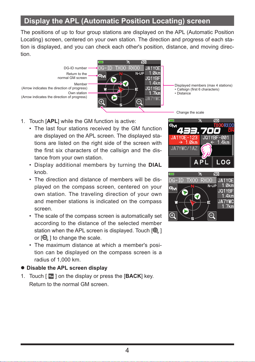
In addition to knowing who is in the service area, the APL (Automatic Position Locat-
ing) screen indicates the positions of the group members, centered on your own station
(up to four are simultaneously displayed). The direction and progress of each station is
displayed, and you can check each other's position, distance, and moving direction.
You can also use GM functions to send data such as messages and images with your
friends.
• When the GM function is activated, the operating band is automatically switched to the A
band, and the communication mode is switched to the C4FM digital (DN) mode.
• To use the GM function, all of the members must operate on the same frequency.
• Note that when the receive DG-ID number of your transceiver is set to a DG-ID number
other than “00”, received signals that do not have the same DG-ID number may not be
heard.
Insert a commercially available micro-SD card into this unit to send and receive messages
and images.
Usable micro-SD Memory Cards
This transceiver only supports the following capacity of micro-SD and micro-SDHD memory
cards.
• 2GB • 4GB • 8GB • 16GB • 32GB
Not all micro-SD and micro-SDHC cards sold commercially are guaranteed to work with this
product. In addition, micro-SDXC memory cards are not supported.

3
GM Operation
1. Tune to the frequency used by the group that you would like to communicate with.
• If you only want to check your group location information, press and the [F MENU]
key touch [GM] and set the send and receive DG-ID numbers to the same num-
bers except “00” at all the partner stations.
• The frequency cannot be changed while the GM function is operating.
2. Press the [GM/X] key.
• The callsign, distance, and direction of all stations (up to 24) within the communi-
cation range operating with the GM function on the designated frequency in DN
(V/D) mode are displayed.
• The call sign of the member who can communicate is displayed in white charac-
ters, and the distance and direction of the member from your own station are dis-
played.
• Stations outside the sphere of communications callsigns are displayed in grey.
• You can communicate in DN mode of C4FM digital by pressing the PTT switch.
Selected member
Out of range
Direction
Distance
In range

4
Display the APL (Automatic Position Locating) screen
The positions of up to four group stations are displayed on the APL (Automatic Position
Locating) screen, centered on your own station. The direction and progress of each sta-
tion is displayed, and you can check each other's position, distance, and moving direc-
tion.
DG-ID TX00 RX00
DG-ID number
Displayed members (max 4 stations)
• Callsign (first 6 characters)
• Distance
Return to the
normal GM screen
Change the scale
Own station
(Arrow indicates the direction of progress)
Member
(Arrow indicates the direction of progress)
1. Touch [APL] while the GM function is active:
• The last four stations received by the GM function
are displayed on the APL screen. The displayed sta-
tions are listed on the right side of the screen with
the first six characters of the callsign and the dis-
tance from your own station.
• Display additional members by turning the DIAL
knob.
• The direction and distance of members will be dis-
played on the compass screen, centered on your
own station. The traveling direction of your own
and member stations is indicated on the compass
screen.
• The scale of the compass screen is automatically set
according to the distance of the selected member
station when the APL screen is displayed. Touch [ ]
or [ ] to change the scale.
• The maximum distance at which a member's posi-
tion can be displayed on the compass screen is a
radius of 1,000 km.
DG-ID TX00 RX00
zDisable the APL screen display
1. Touch [ ] on the display or press the [BACK] key.
Return to the normal GM screen.

5
Confirm the location of a Group Member station in real time
The position of the selected member can be confirmed in real time on the compass
screen.
The member's current position may be registered as the navigation destination.
Display the position of the member station on the compass screen
1. Press the [GM/X] key.
2. Touch the station for which you want to display location
information.
1. Press the [F MENU] key Touch [DISP].
If [DISP] is not displayed, touch [FWD →] to display [DISP] and then touch it.
If the GPS information screen is displayed, touch the compass display to switch to
the navigation display screen.
The call sign and direction, distance, and heading of the selected partner station are
displayed.
JA1YOE-123 1.0km
Callsign and distance to
partner station
Progress direction of
own station
Direction of remote station
H-UP: Heading Up
N-UP: North Up
zSwitch the compass screen display method
Press and hold the [F MENU] key touch [DISPLAY] [3 COMPASS], select the
screen display method (direction toward the top of the screen) from “HEADING UP”
or “NORTH UP”. The default setting is “HEADING UP”.
HEADING UP: The compass circle indicates the direction ( , , and ) you are
heading. The arrow indicates the direction toward your partner sta-
tion.
NORTH UP: Always displays the north ( ) on the top. The arrow indicates the di-
rection you are heading.
zDisable the Compass screen display
1. Press the [F MENU] key.

6
• You cannot update the location information of the partner stations outside of
communication range.
• If your station or your partner stations do not set the location information manually or
capture it from the GPS satellite signals, the compass display is not available.
• GPS location information may have an error of several hundred meters depending on the
surrounding environment and so on.
• This function is a simple function using GPS satellite data. Use this as a guide for the
position of your own station or partner station.
Registering the Location Information of a Partner Station
You can register the current position of the selected member, and then navigate toward
that station.
1. Touch [MEM] in step 3 of “Display the position of the
partner station on the compass screen” (page 5).
[★], [L1] and [L2] will start blinking.
2. Touch [★], [L1] or [L2].
• The Callsign and location information of your partner
station is registered, and the Navigation starts.
• To cancel the registration, touch [MEM] again.
• The registered location information can be recalled
later to allow navigation to that point.
N-UP
JA1YOE-123 1.0km
JA1YOE-123 1.0km

7
Checking Received Messages and Images
Use the GM function to check the messages and images on the LOG list.
• When using a GM function, a beep sounds when a new message is received, and the “LOG
MSG” list screen (see step 3 below) appears automatically.
• When using a GM function, a beep sounds when a new image is received, and the image
appears automatically. Touch [SAVE] to save the received image, or touch [DEL] to not
save it.
1. Press the [GM/X] key.
2. Touch [LOG].
3. Touch [MESSAGE] or [PICT].
VOICE: Audio recorded (Only playback of record-
ed content is possible.)
MESSAGE: Text Message
PICT: Image
PICT
MESSAGE
VOICE
Select “MESSAGE” or “PICT” to display the LOG MSG
list or LOG PICT list.
The icons on the left side of the LOG list indicate the
following:
Message received (unread)
Message received (read)
Message sent
Message failed to send
Image received (unread)
Image received (read)
Image sent
Image failed to send
Image taken with the camera built in the optional
microphone
JA1YOE-123 00/00
JA1YOE-123 00/00
JA1YOE-123 00/00
JA1YOE-123 00/00
NEW
4. Touch the message or image to be displayed.
• The selected message or image will be displayed.
• When the message list is displayed, press the [F MENU] key Touch [DISP]to dis-
play the location information of the sending station on the compass screen.

8
• When the picture is displayed, press the [F MENU] key Touch [DISP]to display
the location where the picture was taken on the compass screen.
• Touch [FWD], to forward the checked message or image data. Refer to
“Forwarding the Checked Message or Image Data” (Page 12).
• Touch [REPLY], To reply to the sender of the downloaded message or image data.
Refer to “Replying to the Sender of the Checked Message or Image Data” (page
12).
• Touch [DEL] to display “DELETE ?”. Touch [OK], then touch [OK] to delete the
information.
5. Press the [BACK] key three times.
Returns to the previously viewed screen.

9
Sending massages or images
There are 4 ways to send messages or images using the GM function:
(1) Creating and sending a new message
(2) Replying to the sender of the checked message or image data
(3) Forwarding the checked message or image data
(4) Sending your snapshot images
Creating and sending a new message
Create and send a new message:
1. Press the [GM/X] key.
2. Touch [LOG].
3. Touch [MESSAGE].
Displays the LOG list. JA1YOE-123 00/00
JA1YOE-123 00/00
JA1YOE-123 00/00
JA1YOE-123 00/00
NEW
4. Touch [NEW].
JA1YOE-123 00/00
JA1YOE-123 00/00
JA1YOE-123 00/00
JA1YOE-123 00/00
NEW
5. Touch [EDIT].
Displays the message entry screen.
NEW

10
6. Refer to “Text input screen” in the FT5DR/DE Operating Manual to enter a message.
• Touch [MTXT] to easily input a message using a standard form.
• In the message input screen, one line is displayed for every 20 characters. Touch
[]/[ ] to move the cursor and display other lines.
7. When input is complete, press the [BACK] key.
The entire message is displayed.
8. Touch [SEND].
• To cancel transmission, touch [BACK].
• To save the entered message as a standard message, touch [SAVE] (page 11).
• To continue message entry, touch [EDIT].
9. Touch [ALL].
• “SEND to ALL ?” appears.
• To send the message to a specific member that is within communication range,
touch the member callsign.
• Messages cannot be sent to members outside of communication range.
• The address designation “to:” is merely for displaying “ALL” or the call sign of a
specific station. If you send a message to a specific member within the communication
range, you can check whether the other station has received it.
• Even if you specify a call sign for “to:” to send a message, other stations operating
GM on the same frequency can also read the message if they are within the
communication range.
10. Touch [OK].
Using Standard Messages
The following 19 standard messages have been saved in the radio's memory as default
to help save time and effort in text input.
1 QRM 8 Good job 15 wait for you
2 QRP 9 Good day 16 Pick me up
3QRT 10 Good evening 17 Thank you
4 QRX 11 Good night 18 OK
5 QRZ 12 Send messages 19 urgent
6 QSY 13 Send pictures - -
7 Good morning 14 on my way - -
1. Follow steps 1 to 5 in “Creating and sending a new message” on page 9 to dis-
play the message entry screen.
2. Touch [MTXT].
• Displays the standard message list.
• For “M01” to “M10”, you can register a message
comprised of up to 80 letters
MTXT

11
3. Rotate the DIAL to select the standard message you
want to use.
4. Touch [PASTE].
• The selected standard message is displayed in the
message entry field.
QRM
QRP
QRT
QRX
5. Press the [BACK] key.
6. The entire message is displayed.
To add letters to the message, input letters following
steps 5 to 6 in “Creating and sending a new message”
on page 9.
NEW
QRM
Registering a standard message
Up to 10 texts containing a maximum of 80 characters each can be registered as stan-
dard messages.
Registered texts can be selected and used like the 19 standard messages that have
been saved as default.
1. Follow steps 1 to 6 in “Creating and sending a new message” on page 9 to dis-
play the message entry screen.
2. Touch [SAVE].
The standard message list is displayed. QRM
Thank you
OK
urgent
M01 ----------------
3. Rotate the DIAL to select the number (M01 to M10)
where you want to register the standard message.
4. Touch [SAVE].
• Registers the text as a standard message and dis-
plays the message entry screen.
• If you register a new message to a number where a
message is already registered, the old message is
overwritten.
• To cancel registration, press the [BACK] key.
QRM
M01 ----------------
M02 ----------------
M03 ----------------
M04 ----------------

12
Replying to the Sender of the Checked Message or Image Data
After checking the message or image data, you may reply to the sender.
1. Select the information (MESSAGE or PICT) to review according to steps 1 to 4 of
“Checking Received Messages and Images” (page 7).
Displays the selected data.
2. Touch [REPLY].
The call sign of the station that sent MESSAGE or PICT to the destination is set au-
tomatically.
3. Touch [EDIT].
Displays the message entry screen.
4. Follow steps 1 to 6 in “Creating and sending a new message” on page 9 to
display the message entry screen.
5. Press the [BACK] key.
Displays the entire message.
6. Touch [SEND].
Sends the reply message to the sender of the MESSAGE/PICT data.
Forwarding the Checked Message or Image Data
After reviewing the message or image data, you may forward the data to other members.
1. Select the information (MESSAGE or PICT) to check according to steps 1 to 4 of
“Checking Received Messages and Images” (page 7).
The selected data is displayed.
2. Touch [FWD].
3. Touch [ALL].
• “SEND to ALL ?” appears.
• To send the message to a specific member that is within communication range,
touch the member callsign.
• Messages cannot be sent to members outside of communication range.
• The address designation “to:” is merely for displaying “ALL” or the call sign of a
specific station. If you send a message to a specific member within the communication
range, you can check whether the other station has received it.
• Even if you specify a call sign for “to:” to send a message, other stations operating
GM on the same frequency can also read the message if they are within the
communication range.
4. Touch [OK].
Messages and images will be transferred.

13
Sending Your Snapshot Images
Take still images using the optional speaker microphone with built-in snapshot camera
(MH-85A11U) and send them to the group members.
For details on how to send images taken with the optional speaker microphone built-in
snapshot camera (MH-85A11U), refer to “Taking Picture (Snapshot Function)” in FT5DR/DE
Operating Manual.
1. Press the [GM/X] key.
The GM function activates and displays stations using
the GM mode on the same frequency, or stations oper-
ating in DN mode, within the communication range.
2. Touch [LOG].
3. Touch [PICT].
Displays the list of images saved on the micro-SD
memory card JA1YOE-123 06/02
JA1YOE-123 05/24
JA1YOE-123 03/14
JA1YOE-123 02/14
JA1YOE-123 16:24
4. Touch the image you want to send.
Displays the selected image.
5. Touch [SEND].
6. Touch [ALL].
• “SEND to ALL ?” appears.
• To send the message to a specific member, touch the member that is within com-
munication range.
• Messages cannot be sent to members outside of communication range.
• The address designation “to:” is merely for displaying “ALL” or the call sign of a
specific station. In other words, even if you specify a call sign for “to:” to send a
message, other stations operating GM on the same frequency can also read the
message if they are within the communication range.
7. Touch [OK].
Sends the image.

14
GM Set Mode List
Set mode item No./item Descriptions
1 DP-ID LIST Displays the DP-ID list screen
2 RADIO ID CHECK Transceiver specific number (ID) appears.
(This cannot be edited)
GM Set Mode Function List
z1 DP-ID LIST
Display of the DP-ID list screen
Explanation: Every C4FM digital transmit communication contains the individual ID
information (Radio ID) of each transceiver. The DP-ID function uses this
individual ID information.
When communicating with another transceiver, if the DP-IDs of the sta-
tions are registered in both transceivers, they can communicate even
though the DG-ID numbers are different.
For details, refer to the FT5DR/DE operating Manual.
z2 RADIO ID CHECK
Display of RADIO ID
Explanation: In the GM function, each transceiver transmits its own ID along with the
call sign.
RADIO ID is a 5-digit code consisting of alphanumeric characters that are
written into the transceiver during factory production.
The RADIO ID cannot be edited.

Copyright 2021
YAESU MUSEN CO., LTD.
All rights reserved.
No portion of this manual may be
reproduced without the permission of
YAESU MUSEN CO., LTD.
Tennozu Parkside Building
2-5-8 Higashi-Shinagawa, Shinagawa-ku, Tokyo 140-0002 Japan
YAESU USA
6125 Phyllis Drive, Cypress, CA 90630, U.S.A.
YAESU UK
Unit 12, Sun Valley Business Park, Winnall Close
Winchester, Hampshire, SO23 0LB, U.K. 2108-A
This manual suits for next models
1
Table of contents
Other Yaesu Transceiver manuals

Yaesu
Yaesu FT-1900E User manual

Yaesu
Yaesu FT-7100M Manual

Yaesu
Yaesu CHATNOW 75028 Series Manual

Yaesu
Yaesu FTA-750 Spirit User manual

Yaesu
Yaesu FT-901DM Manual

Yaesu
Yaesu FT-2900R Manual

Yaesu
Yaesu VX-170 User manual

Yaesu
Yaesu 20663X20 User manual

Yaesu
Yaesu FTM-300DR User manual

Yaesu
Yaesu FT-107M Manual

Yaesu
Yaesu FTM-350 - APRS User manual

Yaesu
Yaesu FT-891 User manual

Yaesu
Yaesu FT DX 1200 User manual

Yaesu
Yaesu FT-767GX User manual

Yaesu
Yaesu FT-101EX User manual

Yaesu
Yaesu FTDX1200 Series Manual

Yaesu
Yaesu FT-301 User manual

Yaesu
Yaesu FT-100 Micro Mobile User manual

Yaesu
Yaesu FT-80C - SERVICE User manual

Yaesu
Yaesu FT-450D User manual