2
Contents
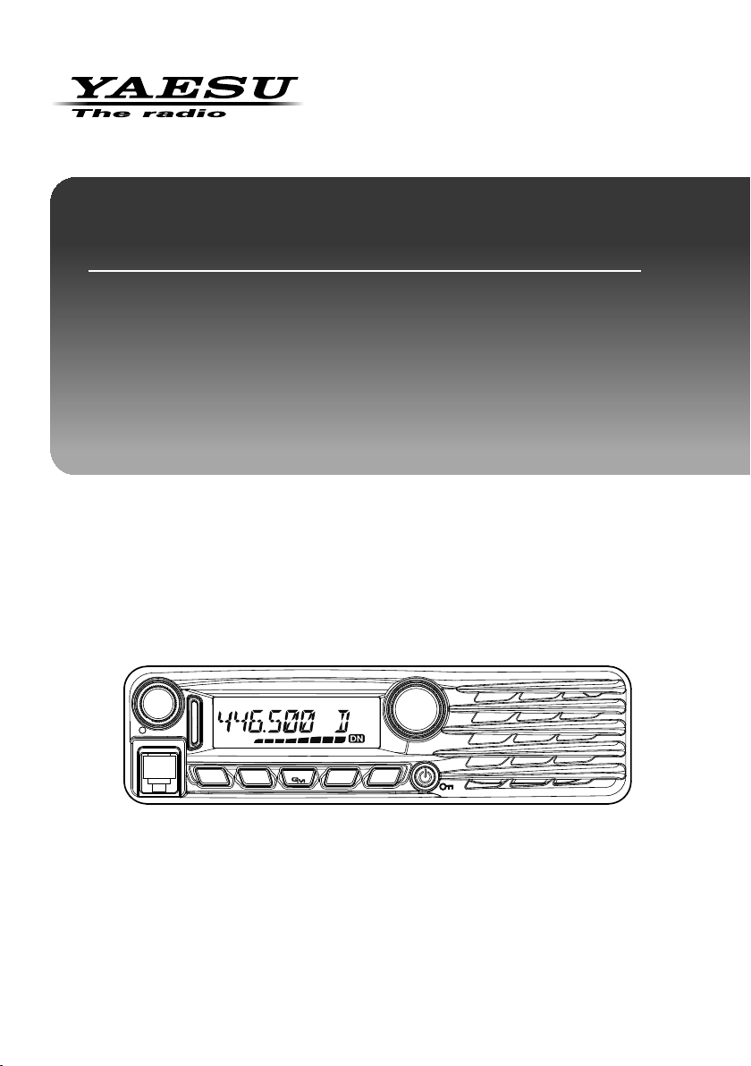
FTM-3207DR/DE Operating Manual
Safety Precautions (Be Sure to Read).................... 3
FTM-3207DR/DE Quick Reference Guide ............... 5
Introduction............................................................... 6
Features of this radio............................................... 6
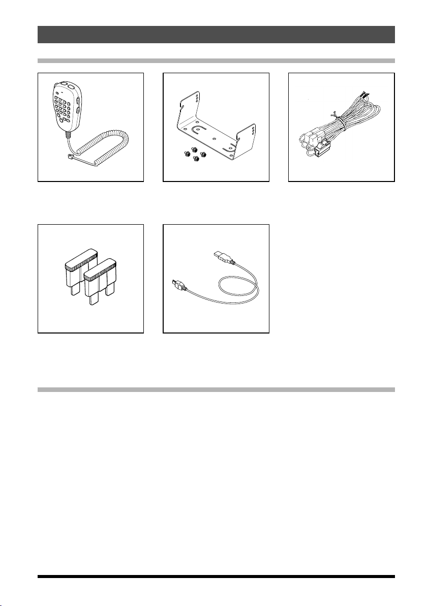
Accessories & Options ............................................ 7
Supplied Accessories .............................................. 7
Optional Accessories ............................................... 7
Installation................................................................. 8
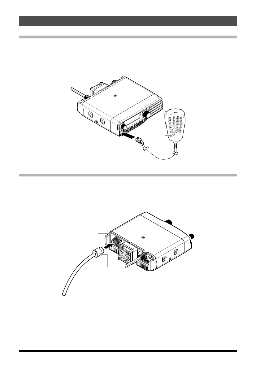
Connecting the Microphone..................................... 8
Connecting the Antenna .......................................... 8
Mobile Installation.................................................... 9
Power connection ............................................... 10
Base Station Installation .........................................11
AC Power Supplies..............................................11
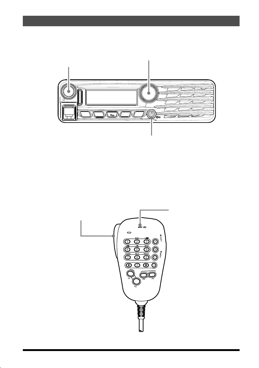
Front Panel Controls & Switches.......................... 12
Front Panel ............................................................ 12
Microphone Switches............................................. 14
Microphone (MH-48A6JA) ..................................... 14
[P1] button .......................................................... 14
[P2] button .......................................................... 14
[P3] button (Wires-X) .......................................... 14
[P4] button (TX PW/T.CALL)............................... 14
Rear Panel Connectors.......................................... 15
Rear Panel............................................................. 15
Basic Operation...................................................... 16
Turning the Transceiver ON and OFF ................... 16
Inputting the call sign............................................. 16
Adjusting the Audio Volume Level ......................... 16
Adjusting the Squelch Setting................................ 16
Frequency Navigation............................................ 17
Using the Dial ..................................................... 17
Using the MH-48A6JA Microphone..................... 17
Channel Step Selection ......................................... 17
Selecting the communication mode....................... 18
Setting the transmission mode when using the
AMS function ...................................................... 19
Transmission ......................................................... 20
Adjusting the transmit power .............................. 21
Lock Feature.......................................................... 21
Advanced Operation .............................................. 22
About the Digital Group ID (DG-ID) feature........... 22
Register the DG-ID number in the
DG-ID memory.................................................... 22
Recall and use the DG-ID number registered
in the DG-ID memory.......................................... 23
Restore the DG-ID number to “00” for
both transmit and receive without using the
DG-ID memory.................................................... 24
Use the GM (Group Monitor) with the
DG-ID function.................................................... 24
Digital Personal ID (DP-ID) feature ....................... 25
Registering the DP-ID to a DR-2X
digital repeater.................................................... 25
Register the transceivers.................................... 25
Deleting the registered DP-ID............................. 26
Advanced Operation .............................................. 27
Repeater Operation ............................................... 27
Checking the Repeater
Uplink (Input) Frequency .................................... 27
Tone Calling (1750 Hz) ....................................... 27
CTCSS Operation.................................................. 28
Tone Search........................................................ 28
DCS Operation ...................................................... 28
DCS Search........................................................ 29
EPCS (Enhanced Paging &
Code Squelch) Operation ...................................... 29
Split Tone Operation .............................................. 29
DTMF Operation.................................................... 29
Memory Operation.................................................. 30
Memory Storage .................................................... 30
Split Memory....................................................... 30
Naming a Memory Channel................................ 30
Memory Recall....................................................... 31
Memory Recall from the Microphone Keypad..... 31
Moving Memory Data to the VFO .................... 31
Memory Only Mode ............................................ 31
Masking Memories ................................................ 32
Unmasking Memories......................................... 32
HOME Channel Memory ....................................... 32
Changing the frequency of the home channel.... 32
Scanning ................................................................. 33
Basic Scanner Operation....................................... 33
Scan Resume Options........................................ 33
Memory Skip Scanning....................................... 33
Preferential Memory Scan .................................. 33
Programmable Memory Scan (PMS).................. 33
Priority Channel Scanning (Dual Watch) ............ 33
GM Function............................................................ 34
What is the GM (Group Monitor) Function?........... 34
Displaying all the stations using the GM function
... 34
Reset Procedure/Clone.......................................... 35
Reset Procedure.................................................... 35
Microprocessor Resetting................................... 35
Setup (Menu) Mode Resetting............................ 35
Clone ..................................................................... 35
Connecting the WIRES-X feature.......................... 36
What is WIRES-X? ................................................ 36
Connecting to a WIRES-X digital node
(Recommended)................................................ 36
Connecting to the other node ID or the
other room ID...................................................... 36
Connect and communicate with WIRES-X in
analog mode.......................................................... 39
Disconnecting from the node or room................. 39
Miscellaneous Settings.......................................... 40
Programming the Key Assignments ...................... 40
Keyboard Beeper................................................... 40
Display Brightness................................................. 40
Time-Out-Timer (TOT) ........................................... 40
Automatic Power Off (APO)................................... 40
Busy Channel Lock-Out (BCLO) ........................... 40
TX Deviation Level ................................................ 40
MIC Gain Setting ................................................... 40
Displaying the Supply Voltage............................... 41
Displaying the Temperature ................................... 41
Band Edge Beeper ................................................ 41
Setup (Menu) Mode ................................................ 42
Maintenance............................................................ 45
Care and maintenance .......................................... 45
Replacing the fuse................................................. 45
Replacing the fuse of the
DC power supply cable....................................... 45
Specifications ......................................................... 46
EU Declaration of Conformity ............................. 48