Yaesu VX-8R/E User manual

Specification ........................................................................................................................................................................... 2
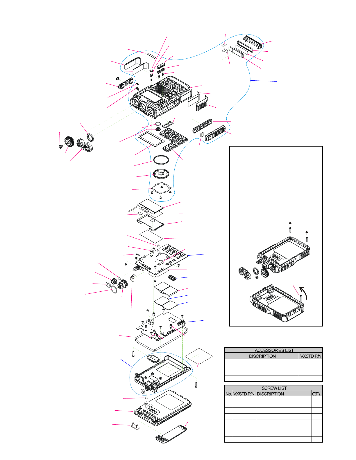
Exploded View & Miscellaneous Parts ............................................................................................................................. 4
Block Diagram ....................................................................................................................................................................... 5
Alignment ............................................................................................................................................................................... 7
Board Unit (Schematics, Layouts & Parts)
RF Unit (Lot.1~4) VX-8R Type Only ............................................................................................................................. 25
RF Unit (Lot.5~7) VX-8R Type Only ............................................................................................................................. 27
RF Unit Parts List (Lot.1~7) VX-8R Type Only ........................................................................................................... 29
RF-2 Unit (Lot.8~15) VX-8R Type Only ....................................................................................................................... 47
RF-2 Unit (Lot.16~) VX-8R/E Type ............................................................................................................................... 49
RF-2 Unit (Lot.24~) VX-8DR/E Type ............................................................................................................................ 51
RF-2 Unit Parts List (Lot.8~) VX-8R and VX-8DR/E Type ......................................................................................... 53
CNTL Unit (Lot.1~4) VX-8R Type Only ....................................................................................................................... 73
CNTL Unit (Lot.5~7) VX-8R Type Only ....................................................................................................................... 75
CNTL Unit Parts List (Lot.1~7) VX-8R Type Only ..................................................................................................... 77
CNTL-2 Unit (Lot.8~15) VX-8R Type Only .................................................................................................................87
CNTL-2 Unit (Lot.16~) VX-8R/E Type ......................................................................................................................... 89
CNTL-2 Unit (Lot.24~) VX-8DR/E Type ...................................................................................................................... 91
CNTL-2 Unit Parts List (Lot.8~) VX-8R/E and VX-8DR/E Type ............................................................................... 93
CONNECTOR Unit (Lot.1~7) VX-8R Type Only....................................................................................................... 103
CONNECTOR-2 Unit (Lot.8~) VX-8R/E and VX-8DR/E Type ................................................................................. 105
MAIN VCO Unit VX-8R/E and VX-8DR/E Type .......................................................................................................107
SUB VCO Unit VX-8R/E and VX-8DR/E Type ........................................................................................................... 113
©2010 VERTEX STANDARD CO., LTD. Printed in Japan.
Technical Supplement
VX-8R/E
VX-8DR/E
50/144/430 MHz Triple-Band
Heavy Duty Submersible Transceiver
Introduction
This manual provides the technical information necessary for servicing the VX-8R/E
and VX-8DR/E 50/144/430 MHzTriple-Band Heavy Duty Submersible Transceiver.
Servicing this equipment requires expertise in handing surface-mount chip components.
Attempts by non-qualified persons to service this equipment may result in permanent
damage not covered by the warranty, and may be illegal in some countries.
Two PCB layout diagrams provided for each double-sided board in this transceiver.
Each side of the board is referred to by the type of the majority of components installed on
that side ("Side A" or "Side B"). In most cases one side has only chip components, and the
other has either a mixture of both chip and leaded components (trimmers, coils, electrolytic
capacitors, ICs, etc.), or leaded components only.
While we believe the information in this manual to be correct, VERTEX STANDARD
assumes no liability for damage that may occur as a result of typographical or other errors
that may be present. Your cooperation in pointing out any inconsistencies in the technical
information would be appreciated.
Contents
EH029M90F
VERTEX STANDARD CO., LTD.
4-8-8 Nakameguro, Meguro-Ku, Tokyo 153-8644, Japan
VERTEX STANDARD
US Headquarters
10900 Walker Street, Cypress, CA 90630, U.S.A.
YAESU UK LTD.
Unit 12, Sun Valley Business Park, Winnall Close
Winchester, Hampshire, SO23 0LB, U.K.
VERTEX STANDARD HK LTD.
Unit 5, 20/F., Seaview Centre, 139-141 Hoi Bun Road,
Kwun Tong, Kowloon, Hong Kong
VERTEX STANDARD (AUSTRALIA)PTY., LTD.
Normanby Business Park, Unit 14/45 Normanby Road
Notting Hill 3168, Victoria, Australia
Important Note
1) This transceiver was assembled using Pb (lead) free solder, based on the RoHS specification.
Only lead-free solder (Alloy Composition: Sn-3.0Ag-0.5Cu) should be used for repairs performed on this apparatus. The solder stated
above utilizes the alloy composition required for compliance with the lead-free specification, and any solder with the above alloy
composition may be used.
2) Risk of explosion if battery is replaced by an incorrect type. Dispose of used batteries according to the instructions.

2VX-8R/E and VX-8DR/E Technical Supplement
Specifications
GENERAL
Frequency Ranges: A (Main) Band RX: 0.5-1.8 MHz (AM Radio)
1.8-30 MHz (SW Band)
30-76 (88*) MHz (50 MHz HAM)
76 (88*) - 108 MHz (FM Radio)
108 - 137 MHz (Air Band)
137-174 MHz (144 MHz HAM)
174 - 222 MHz (VHF-TV)
222 - 420 MHz (General 1)
420 - 470 MHz (430 MHz HAM)
470 - 774 MHz (UHF-TV)
774 - 999.90 MHz (General 2, Cellular Blocked)
B (Sub) Band RX: 30 - 76 (88*) MHz (50 MHz HAM)
108 - 137 MHz (Air Band)
137 - 174 MHz (144 MHz HAM)
174 - 222 MHz (VHF-TV)
222 - 420 MHz (General 1)
420 - 580 MHz (430 MHz HAM)
TX: 50 - 54 MHz or 50-52 MHz
144 - 146 MHz or 144-148 MHz
222 - 225 MHz (USA version only)
430 - 440 MHz or 430-450 MHz
Channel Steps: 5/6.25/8.33/9/10/12.5/15/20/25/50/100 kHz
Emission Type: F1D, F2A, F2D, F3E, A3E
Frequency Stability: ±5 ppm (–10 °C to +60 °C [+14 °F to +140 °F])
Repeater Shift: ±600 kHz (144 MHz), ±1.6 MHz (222 MHz), ±1.6/5.0/7.6 MHz (430 MHz)
AntennaImpedance: 50 Ohms
Supply Voltage: Nominal: 7.4 V DC (Negative Ground)
Operating: 4-14 V DC (Negative Ground, EXT DC jack)
Operating with Charging: 11-14 V DC (Negative Ground, EXT DC jack)
Current Consumption: 200 mA (Mono Band Receive)
(@7.4 VDC, approx.) 240 mA (Dual Band Receive)
85 mA (Mono Band Receive, Standby, Saver Off)
120 mA (Dual Band Receive, Standby, Saver Off)
35 mA (Mono Band Receive, Standby, Saver On “Save Ratio 1:5”)
42 mA (Dual Band Receive, Standby, Saver On “Save Ratio 1:5”)
300 µA (Auto Power Off)
1.6 A (50 MHz, 5 W TX)
1.7A (144 MHz, 5W TX)
1.2 A (222 MHz, 1.5 W TX)
1.9 A (430 MHz, 5W TX)
Operating Temperature
: –20 °C to +60 °C (–4 °F to +140 °F)
–25 °C to +55 °C*
–5 °C to +35 °C* (Battery Charging)
Case Size (W x H x D): 60 x 95 x 24.2 mm (2.4” x 3.7” x 0.9”) w/o knob & antenna
Weight (Approx.): 240 g (8.5 oz) with FNB-101LI & antenna
*: VX-8E and VX8DE Type

3VX-8R/E and VX-8DR/E Technical Supplement
Specifications
TRANSMITTER
RF Power Output: 50/144/430 MHz 1.0 W (@4.5 V: AA x 3)
5.0 W (@7.4 V or EXT DC)
50 MHz AM 1.0 W (Fixed)
222 MHz (USA only) 0.5 W (@4.5 V: AA x 3)
1.5 W (@7.4 V or EXT DC)
L3: 2.5 W, L2: 1 W, L1: 0.05 W (0.2 W*) (@7.4 V, 50/144/430 MHz)
L3: 1 W, L2: 0.5 W, L1: 0.05 W (@7.4 V, 222 MHz)
ModulationType: F2E, F3E: Variable Reactance
A3E: Low Level Amplitude Modulation (50 MHz only)
MaximumDeviation: ±5 kHz (F2E/F3E)
Spurious Emission: At least 60 dB below (@ TX power HI/L3)
At least 50 dB below (@ TX power L2/L1)
MicrophoneImpedance:2k Ohms
RECEIVER
Circuit Type: NFM, AM: Double-Conversion Superheterodyne
WFM: Triple-Conversion Superheterodyne
AM/FM Radio: Single-Conversion Superheterodyne
IF: NFM, AM 1st: 47.25 MHz (A (Main) Band),
46.35 MHz (B (Sub) Band),
2nd: 450kHz
WFM 1st: 45.8 MHz, 2nd: 10.7 MHz, 3rd: 1 MHz
AM/FM Radio: 130kHz
Sensitivity: 3.0 µV for 10 dB S/N (0.5-30 MHz @AM)
(A (Main) Band) 0.35 µV (TYP) for 12 dB SINAD (30-54 MHz @NFM)
1.0 µV (TYP) for 12 dB SINAD (54-76 MHz @NFM)
1.0 µV (TYP) for 12 dB SINAD (54-59 MHz @NFM, USAVersion)
0.5 µV (TYP) for 12 dB SINAD (76-88 MHz @NFM)*
1.5 µV (TYP) for 12 dB SINAD (76-108 MHz @WFM)
1.5 µV (TYP) for 12 dB SINAD (88-108 MHz @WFM)*
1.5 µV (TYP) for 12 dB SINAD (59-108 MHz @WFM, USAVersion)
1.5 µV (TYP) for 10 dB SN (108-137 MHz @AM)
0.2 µV for 12 dB SINAD (137-140 MHz @NFM)
0.16 µV for 12 dB SINAD (140-150 MHz @NFM)
0.2 µV for 12 dB SINAD (150-174 MHz @NFM)
1.0 µV for 12 dB SINAD (174-222 MHz @WFM)
0.5 µV for 12 dB SINAD (300-350 MHz @NFM)
0.2 µV for 12 dB SINAD (350-400 MHz @NFM)
0.18 µV for 12 dB SINAD (400-470 MHz @NFM)
1.5 µV for 12 dB SINAD (470-540 MHz @WFM)
3.0 µV (TYP) for 12 dB SINAD (540-800 MHz @WFM)
1.5 µV (TYP) for 12 dB SINAD (800-999.90 MHz @NFM) (Cellular Blocked)
Sensitivity: 0.18 µV(TYP) for 12 dB SINAD (50-54 MHz @NFM)
(B (Sub) Band) 0.18 µV for 12 dB SINAD (144-148 MHz @NFM)
0.2 µV for 12 dB SINAD (430-450 MHz @NFM)
Selectivity: 12 kHz/35 kHz (–6dB/–60dB: NFM, AM)
200 kHz/300 kHz (–6dB/–20dB: WFM)
AFOutput: 200 mW @ 8 Ohms for 10 % THD (@ 7.4 V DC)
400 mW @ 8 Ohms for 10 % THD (@ 13.8 V DC)
Specifications are subject to change without notice, and are guaranteed within the 50/144/(222)/430 MHz amateur bands only.
Cellular Blocked per FCC rule Part 15.121, may not receive 900 MHz Amateur band.
The frequency ranges are different according to a transceiver version.
*: VX-8E and VX-8DE Type

4VX-8R/E and VX-8DR/E Technical Supplement
Exploded View & Miscellaneous Parts
Non-designated parts are available only as part of a
designated assembly.
1. Please order the screw M2.6X30 (P/N;
U00230001).
2. Remove the SPECIAL SCREW (A) and
ENCODER KNOB (B).
3. Remove the MIC/SP CAP (C) and RING
NUT (D).
4. Remove the two screws (E).
5. Turn the M2.6x30 screw several times to
affix the screw to the bottom right corner.
6. Press the top of the screw toward to a panel
top to remove the rear case Assy from the
front panel.
Removing the Rear Case Assy
screw M2.6X30
(A)
(B)
(C) (D)
(E)
(E)
RA1012900
SHEET (MIC)
M4090189
SPEAKER(0.5W/16-ohm)
RA105780A
FRONT CASE
(W/ SP NET, WINDOW)
RA1016400
LIGHT GUIDE (LED)
RA1016600
HOLDER (ANT)
RA101670B (x2 pcs)
SUPPORT (ACS)
RA1016900
SUPPORT (PTT)
RA1016800
SUPPORT (POW)
RA1017100
PROTECTOR (L)
RA1014200
SHEET HOLDER (MIC)
RA1017000
PROTECTOR (R)
RA1049000
ENCODER KNOB (2PRY)
CP9295001
CHASSIS ASSY
(w/ PACKING PAD, O RING,
SMA CONNECTOR)
RA1093500
MYLAR SHEET (ANT)
RA1092400
SHEET (SW)
RA107300A
SPACER (PTT)
RA1070500
LIGHT SHEET (LCD)
RA106950A
SHEET (ACS)
RA1061400
O RING (12.5X1)
RA1066900
BLIND SHEET
RA0337300
SHEET (C012)
RA0603200
O RING (0.7X3.7)
RA1042800
RING NUT (WITCO)
RA060450B
SPECIAL NUT (M)
RA0918600
SPECIAL SCREW (2.6X5X8)
RA1053700 (x3 pcs)
COIL SPRING
RA1011800 (x2 pcs)
STUD
RA1057200
DOUBLE FACE (PAD-R)
RA1057100
DOUBLE FACE (PAD-L)
RA1017600
SHEET (LED)
RA1017500
SHEET (WIN)
RA1013900
DOUBLE FACE (ANT-A)
RA101370B
SP HOLDER
RA0603600
O RING (1X4.2)
RA1037500
O RING (6.5X2)
RA1013300
RUBBER PACKING (LED)
RA1013500
RUBBER PACKING (ANT)
RA101340B
RUBBER PACKING (SP)
RA101320A
RUBBER KEY (PTT)
RA101250A
KEY PAD
RA1017200
CAP (TOP)
RA1017300
CAP (SIDE)
RA1012700
GASKET
RA101300B (x2 pcs)
RUBBER KEY (ACS)
RA101310A
RUBBER KEY (POW)
RA1016500
LCD HOLDER
RA1013800
SHEET (LCD)
RA1017400 (x2 pcs)
DOUBLE FACE (LCD)
RA1080500
SHIELD SHEET
Q7000614
LCD MODULE
MAIN VCO Unit
SUB VCO Unit
CONNECTOR Unit
CNTL Unit
Q9000881
BAR ANTENNA
P0091520
CONNECTOR
FR018900A
MIC-CONNECTOR Flat Cable
RF Unit
RA1054200
CAP (BATT)
RA1053600
BELT CLIP
AAG10X001
FNB-101LI
RA1007400 (x2 pcs)
SHIELD CASE VCO
RA0951900
NAME PLATE (YAESU)
Q3000183
Q3000185
Q9500149
Q9500150
RUBBER ANTENNA YHA-64
RUBBER ANTENNA YHA-65 (USA)
AC-DC ADAPTOR NC-86B (USA)
AC-DC ADAPTOR NC-86C (EXP)
U9900240
U9900239
U9900241
U07230102
U24310020
U9900242
U9900243
U9900181
PAN HEAD TAPTITE-B 1.4X3NI #3
PAN HEAD TAPTITE-B 2X3NI #3
PAN HEAD TAPTITE-B 2X10SUS #3
PAN HEAD SCREW M2X3NI #1
BIND HEAD TAPTITE-B M3X10SUS
TAPPING SCREW 2X2.5NI
TAPPING SCREW M2X3NI
TAPTITE SCREW 2X3.5(CAP)
2
11
2
1
2
4
2
1
RA1092400 (x2 pcs)
SHEET (SW)
FR018660A
ANT Flat Cable
CP9296002 (USA)
CP9296003 (EXP)
CP9296004 (EU)
CP9296005 (AUS)
FRONT CASE ASSY

5VX-8R/E and VX-8DR/E Technical Supplement
Block Diagram

6VX-8R/E and VX-8DR/E Technical Supplement
Block Diagram
Note

7VX-8R/E and VX-8DR/E Technical Supplement
Alignment
Introduction and Precautions
The and has been carefully aligned
at the factory for the specified performance across the
specified amateur bands. Realignment should therefore
not be necessary except in the event of a component fail-
ure. All component replacement and service should be
performed only by an authorized VERTEX STANDARD
representative, or the warranty policy may be voided.
The following procedures cover the sometimes critical
and tedious adjustments that are not normally required
once the transceiver has left the factory. However, if dam-
age occurs and some parts are replaced, realignment may
be required. If a sudden problem occurs during normal
operation, it is likely due to component failure; realign-
ment should not be done until after the faulty compo-
nent has been replaced.
We recommend that servicing be performed only by
authorized VERTEX STANDARD service technicians,
who are experienced with the circuitry and fully
equipped for repair and alignment. Therefore, if a fault
is suspected, contact the dealer from whom the trans-
ceiver was purchased for instructions regarding repair.
Authorized VERTEX STANDARD service technicians
realign all circuits and make complete performance
checks to ensure compliance with factory specifications
after replacing any faulty components.
Those who do undertake any of the following align-
ments are cautioned to proceed at their own risk. Prob-
lems caused by unauthorized attempts at realignment
are not covered by the warranty policy. Also, VERTEX
STANDARD must reserve the right to change circuits
and alignment procedures in the interest of improved
performance, without notifying owners.
Under no circumstances should any alignment be at-
tempted unless the normal function and operation of the
transceiver are clearly understood, the cause of the mal-
function has been clearly pinpointed and any faulty com-
ponents replaced, and the need for realignment deter-
mined to be absolutely necessary.
Required Test Equipment
HRF Signal Generator with calibrated output level at 500 MHz
HDeviation Meter (linear detector)
HIn-line Wattmeter with 5% accuracy at 500 MHz
H50-ohm, 10-W RF Dummy Load
H8-ohm AF Dummy Load
HRegulated DC Power Supply adjustable from 8 to 16 V DC, 3A
HFrequency Counter: 0.2-ppm accuracy at 500 MHz
HAF Signal Generator
HAC Voltmeter
HDC Voltmeter: high impedance
HUHF Sampling Coupler
HSINAD Meter
Alignment Preparation & Precautions
A 10-W RF dummy load and in-line wattmeter must
be connected to the main antenna jack in all procedures
that call for transmission, alignment is not possible with
an antenna. After completing one step, read the next step
to see if the same test equipment is required. If not, re-
move the test equipment (except dummy load and watt-
meter, if connected) before proceeding.
Correct alignment requires that the ambient tempera-
ture be the same as that of the transceiver and test equip-
ment, and that this temperature be held constant between
68~86°F (20~30°C). When the transceiver is brought into
the shop from hot or cold air, it should be allowed some
time to come to room temperature before alignment.
Whenever possible, alignments should be made with os-
cillator shields and circuit boards firmly affixed in place.
Also, the test equipment must be thoroughly warmed
up before beginning.
Note: Signal levels in dB referred to in the alignment proce-
dure are based on 0 dBµ=0.5 µV (closed circuit).

8VX-8R/E and VX-8DR/E Technical Supplement
Alignment
Internal System Alignment Routine
This uses a programmed routine in the transceiver
which simplifies many previously complex discrete com-
ponent settings and adjustments with digitally-con-
trolled settings via front panel buttons and LCD indica-
tions.
1. To begin, set the transceiver to the VFO mode on the
"A-Band" in the "Mono" band mode.
2. Program a password for the Alignment (AH029M) ac-
cording to the following procedure:
1) Press and hold the [MENU] key for one second to
enter the Set mode.
2) Rotate the DIAL knob to select Set Mode Item 21:
CW ID.
3) Press the [MENU] key briefly to enable adjustment
of this Set Mode Item.
4) Rotate the DIAL knob to select "ON".
5) Press the [MODE] key, then press and hold in the
[HM/RV] key for two seconds to clear any previous
entry.
6) Program the password "AH029M" using the DIAL
knob (select the character), and [BAND]/[MODE]
key (move the cursor).
7) When you have completed the password, press the
[MENU] key briefly, then press the PTT switch to
exit to normal operation.
Remember to delete the password "AH029M"from the
Set Mode Item 21: CW ID when the alignment adjust-
ments are finished by pressing and holding in the [HM/
RV] key for two seconds (as in step 5 above).
3. Press the [PWR] switch for two seconds to turn the
transceiver "off".
4. Press and hold in the [HM/RV] key while powering
the transceiver "on" again. The transceiver will enter
the adjustment mode, and the display will show the
first alignment setting. Thereafter, the frequencies used
during alignment will automatically be set without
action by the technician.
DIAL
[V/M]
[V/M]
[HM/RV]
As each transceiver is individually optimized at the
factory, the precise settings for the transceiver on your
bench may be slightly different.
PLL Reference Frequency Adjustment (PLL REF)
ÌConnect the test equipment as shown in Figure 1: TX
Alignment Setup.
ÌRotate the DIAL knob to select the Alignment Menu
"PLL REF".
ÌPress the [V/M] button (the "" icon will appear on the
display).
ÌPress the PTT switch to transmit and rotate the DIAL
knob so that the frequency counter setting is 440.000
MHz (±100 Hz).
ÌRelease the PTT switch, then press the [V/M] button
(the "" icon will disappear from the display).
Figure 1: TX Alignment Setup
Figure 2: RX Alignment Setup
Wattmeter
In-Line
Dummy Load
50-ohm RF
Coupler
Sampling
Meter
Deviation
Counter
Frequency
Generator
RF Signal
Meter
SINAD
AF Load
8-ohm

9VX-8R/E and VX-8DR/E Technical Supplement
Alignment
A-Band 430 MHz Band Adjustment
Receiver Sensitivity Adjustment (TUNE DC)
ÌConnect the test equipment as shown in Figure 2: RX
Alignment Setup.
ÌRotate the DIAL knob to select the Alignment Menu
"TUNE DC".
ÌSet the RF Signal Generator output to 435.100 MHz, at
a level of -10 dBµ, ±3.5 kHz deviation with a 1 kHz
audio tone.
ÌPress the [V/M] button (the "" icon will appear on the
display).
ÌRotate the DIAL knob for maximum deflection on the
SINAD meter.
ÌPress the [V/M] button (the "" icon will disappear on
the display).
Squelch Hysteresis Confirmation (HIS SQL)
ÌRotate the DIAL knob to select the Alignment Menu
"HIS SQL".
ÌConfirm that the alignment value is "0".
Squelch Threshold Adjustment (THLD SQL)
ÌConnect the test equipment as shown in Figure 2: RX
Alignment Setup.
ÌRotate the DIAL knob to select the Alignment Menu
"THLD SQL".
ÌSet the RF Signal Generator output to 435.100 MHz, at a level
of -12 dBµ, ±3.5 kHz deviation with a 1 kHz audio tone.
ÌPress the [V/M] button (the "" icon will appear on the
display).
ÌPress the [F/W] key two times to store the FM SMeter
Full Scale level.
ÌPress the [V/M] button (the "" icon will disappear on
the display).
Tight Squelch Adjustment (TIGH SQL)
ÌConnect the test equipment as shown in Figure 2: RX
Alignment Setup.
ÌRotate the DIAL knob to select the Alignment Menu
"TIGH SQL".
ÌSet the RF Signal Generator output to 435.100 MHz, at a level
of +4 dBµ, ±3.5 kHz deviation with a 1 kHz audio tone.
ÌPress the [V/M] button (the "" icon will appear on the
display).
ÌPress the [F/W] key two times to store the FM SMeter
Full Scale level.
ÌPress the [V/M] button (the "" icon will disappear on
the display).
FM S-Meter S-1 Adjustment (S1 LEVEL)
ÌConnect the test equipment as shown in Figure 2: RX
Alignment Setup.
ÌRotate the DIAL knob to select the Alignment Menu
"S1 LEVEL" with "NFM" icon.
ÌSet the RF Signal Generator output to 435.100 MHz, at
a level of -7 dBµ, ±3.5 kHz deviation with a 1 kHz au-
dio tone.
ÌPress the [V/M] button (the "" icon will appear on the
display).
ÌPress the [F/W] key two times to store the FM SMeter
Full Scale level.
ÌPress the [V/M] button (the "" icon will disappear on
the display).
FM S-Meter Full-Scale Adjustment (S9 LEVEL)
ÌConnect the test equipment as shown in Figure 2: RX
Alignment Setup.
ÌRotate the DIAL knob to select the Alignment Menu
"S9 LEVEL" with "NFM" icon.
ÌSet the RF Signal Generator output to 435.100 MHz, at
a level of +20 dBµ, ±3.5 kHz deviation with a 1 kHz
audio tone.
ÌPress the [V/M] button (the "" icon will appear on the
display).
ÌPress the [F/W] key two times to store the FM SMeter
Full Scale level.
ÌPress the [V/M] button (the "" icon will disappear on
the display).
Wide FM S-Meter S-1 Adjustment (S1 LEVEL)
ÌConnect the test equipment as shown in Figure 2: RX
Alignment Setup.
ÌRotate the DIAL knob to select the Alignment Menu
"S1 LEVEL" with "WFM" icon.
ÌSet the RF Signal Generator output to 435.100 MHz, at
a level of 0 dBµ, ±20 kHz deviation with a 1 kHz audio
tone.
ÌPress the [V/M] button (the "" icon will appear on the
display).
ÌPress the [F/W] key two times to store the FM SMeter
Full Scale level.
ÌPress the [V/M] button (the "" icon will disappear on
the display).

10 VX-8R/E and VX-8DR/E Technical Supplement
Alignment
Wide FM S-Meter Full-Scale Adjustment (S9 LEVEL)
ÌConnect the test equipment as shown in Figure 2: RX
Alignment Setup.
ÌRotate the DIAL knob to select the Alignment Menu
"S9 LEVEL" with "WFM" icon.
ÌSet the RF Signal Generator output to 435.100 MHz, at
a level of +20 dBµ, ±20 kHz deviation with a 1 kHz
audio tone.
ÌPress the [V/M] button (the "" icon will appear on the
display).
ÌPress the [F/W] key two times to store the FM SMeter
Full Scale level.
ÌPress the [V/M] button (the "" icon will disappear on
the display).
TX Power (HI) Adjustment (HI POWER)
ÌConnect the test equipment as shown in Figure 1: TX
Alignment Setup.
ÌRotate the DIAL knob to select the Alignment Menu
"HI POWER".
ÌPress the [V/M] button (the "" icon will appear on the
display).
ÌPress the PTT switch to transmit and rotate the DIAL
knob so that the Power Meter reading is 5.0 W (±0.1
W).
ÌRelease the PTT switch, and then press the [V/M] but-
ton (the "" icon will disappear on the display).
TX Power (L3) Adjustment (L3 POWER)
ÌConnect the test equipment as shown in Figure 1: TX
Alignment Setup.
ÌRotate the DIAL knob to select the Alignment Menu
"L3 POWER".
ÌPress the [V/M] button (the "" icon will appear on the
display).
ÌPress the PTT switch to transmit and rotate the DIAL
knob so that the Power Meter setting is 2.5 W (±0.1
W).
ÌRelease the PTT switch, and then press the [V/M] but-
ton (the "" icon will disappear on the display).
TX Power (L2) Adjustment (L2 POWER)
ÌConnect the test equipment as shown in Figure 1: TX
Alignment Setup.
ÌRotate the DIAL knob to select the Alignment Menu
"L2 POWER".
ÌPress the [V/M] button (the "" icon will appear on the
display).
ÌPress the PTT switch to transmit and rotate the DIAL
knob so that the Power Meter setting is 1.0 W (±0.1
W).
ÌRelease the PTT switch, and then press the [V/M] but-
ton (the "" icon will disappear on the display).
TX Power (L1) Adjustment (L1 POWER)
ÌConnect the test equipment as shown in Figure 1: TX
Alignment Setup.
ÌRotate the DIAL knob to select the Alignment Menu
"L1 POWER".
ÌPress the [V/M] button (the "" icon will appear on the
display).
ÌPress the PTT switch to transmit and rotate the DIAL
knob so that the Power Meter setting is 50 mW (+30
mW/ -20 mW) (VX-8E Type: 0.2W±0.05W).
ÌRelease the PTT switch, and then press the [V/M] but-
ton (the "" icon will disappear on the display).
TX Deviation Adjustment (MAX DEV)
ÌConnect the test equipment as shown in Figure 1: TX
Alignment Setup.
ÌRotate the DIAL knob to select the Alignment Menu
"MAX DEV".
ÌSet the AF Signal Generator output to 50 mVrms with
a 1 kHz audio tone.
ÌPress the [V/M] button (the "" icon will appear on the
display).
ÌPress the PTT switch to transmit and rotate the DIAL
knob so that the Deviation Meter setting is 4.2 kHz ±
0.2 kHz (USA version) or 4.5 kHz ± 0.2 kHz (EXP/EU
versions).
ÌRelease the PTT switch, and then press the [V/M] but-
ton (the "" icon will disappear on the display).

11VX-8R/E and VX-8DR/E Technical Supplement
Alignment
CTCSS TX Deviation Adjustment (100.0Hz)
ÌConnect the test equipment as shown in Figure 1: TX
Alignment Setup.
ÌRotate the DIAL knob to select the Alignment Menu
"100.0Hz".
ÌPress the [V/M] button (the "" icon will appear on the
display).
ÌPress the PTT switch to transmit without the micro-
phone input and rotate the DIAL knob so that the De-
viation Meter setting is 0.65 kHz (±0.05 kHz).
ÌRelease the PTT switch, and then press the [V/M] but-
ton (the "" icon will disappear on the display).
DCS TX Deviation Adjustment (DCS 023)
ÌConnect the test equipment as shown in Figure 1: TX
Alignment Setup.
ÌRotate the DIAL knob to select the Alignment Menu
"DCS 023".
ÌPress the [V/M] button (the "" icon will appear on the
display).
ÌPress the PTT switch to transmit without the micro-
phone input and rotate the DIAL knob so that the De-
viation Meter setting is 0.65 kHz (±0.05 kHz).
ÌRelease the PTT switch, and then press the [V/M] but-
ton (the "" icon will disappear on the display).
A-Band 50 MHz Band Adjustment
Press the [BAND] key to select the 50 MHz Amateur
band.
Receiver Sensitivity Adjustment (TUNE DC)
ÌConnect the test equipment as shown in Figure 2: RX
Alignment Setup.
ÌRotate the DIAL knob to select the Alignment Menu
"TUNE DC".
ÌSet the RF Signal Generator output to 52.100 MHz, at a
level of -10 dBµ, ±3.5 kHz deviation with a 1 kHz audio
tone.
ÌPress the [V/M] button (the "" icon will appear on the
display).
ÌRotate the DIAL knob for maximum deflection on the
SINAD meter.
ÌPress the [V/M] button (the "" icon will disappear on
the display).
Squelch Hysteresis Confirmation (HIS SQL)
ÌRotate the DIAL knob to select the Alignment Menu
"HIS SQL".
ÌConfirm that the alignment value is "0".
Squelch Threshold Adjustment (THLD SQL)
ÌConnect the test equipment as shown in Figure 2: RX
Alignment Setup.
ÌRotate the DIAL knob to select the Alignment Menu
"THLD SQL".
ÌSet the RF Signal Generator output to 52.100 MHz, at a
level of -12 dBµ, ±3.5 kHz deviation with a 1 kHz audio
tone.
ÌPress the [V/M] button (the "" icon will appear on the
display).
ÌPress the [F/W] key two times to read the Squelch
Threshold level.
ÌPress the [V/M] button (the "" icon will disappear on
the display).

12 VX-8R/E and VX-8DR/E Technical Supplement
Alignment
Tight Squelch Adjustment (TIGH SQL)
ÌConnect the test equipment as shown in Figure 2: RX
Alignment Setup.
ÌRotate the DIAL knob to select the Alignment Menu
"TIGH SQL".
ÌSet the RF Signal Generator output to 52.100 MHz, at a
level of +4 dBµ, ±3.5 kHz deviation with a 1 kHz audio
tone.
ÌPress the [V/M] button (the "" icon will appear on the
display).
ÌPress the [F/W] key two times to read the Squelch Tight
level.
ÌPress the [V/M] button (the "" icon will disappear on
the display).
FM S-Meter S-1 Adjustment (S1 LEVEL)
ÌConnect the test equipment as shown in Figure 2: RX
Alignment Setup.
ÌRotate the DIAL knob to select the Alignment Menu
"S1 LEVEL" with "NFM" icon.
ÌSet the RF Signal Generator output to 52.100 MHz, at a
level of -7 dBµ, ±3.5 kHz deviation with a 1 kHz audio
tone.
ÌPress the [V/M] button (the "" icon will appear on the
display).
ÌPress the [F/W] key two times to store the FM S-Meter
S-1 level.
Press the [V/M] button (the "" icon will disappear on
the display).
FM S-Meter Full-Scale Adjustment (S9 LEVEL)
ÌConnect the test equipment as shown in Figure 2: RX
Alignment Setup.
ÌRotate the DIAL knob to select the Alignment Menu
"S9 LEVEL" with "NFM" icon.
ÌSet the RF Signal Generator output to 52.100 MHz, at a
level of +20 dBµ, ±3.5 kHz deviation with a 1 kHz au-
dio tone.
ÌPress the [V/M] button (the "" icon will appear on the
display).
ÌPress the [F/W] key two times to store the FM S-Meter
Full Scale level.
ÌPress the [V/M] button (the "" icon will disappear on
the display).
Wide FM S-Meter S-1 Adjustment (S1 LEVEL)
ÌConnect the test equipment as shown in Figure 2: RX
Alignment Setup.
ÌRotate the DIAL knob to select the Alignment Menu
"S1 LEVEL" with "WFM" icon.
ÌSet the RF Signal Generator output to 52.100 MHz, at a level
of 0 dBµ, ±20 kHz deviation with a 1 kHz audio tone.
ÌPress the [V/M] button (the "" icon will appear on the
display).
ÌPress the [F/W] key two times to read the Wide FM S-
Meter S-1 level.
ÌPress the [V/M] button (the "" icon will disappear on
the display).
Wide FM S-Meter Full-Scale Adjustment (S9 LEVEL)
ÌConnect the test equipment as shown in Figure 2: RX
Alignment Setup.
ÌRotate the DIAL knob to select the Alignment Menu
"S9 LEVEL" with "WFM" icon.
ÌSet the RF Signal Generator output to 52.100 MHz, at a
level of +20 dBµ, ±20 kHz deviation with a 1 kHz audio
tone.
ÌPress the [V/M] button (the "" icon will appear on the
display).
ÌPress the [F/W] key two times to read the Wide FM S-
Meter Full Scale level.
ÌPress the [V/M] button (the "" icon will disappear on
the display).
TX Power (HI) Adjustment (HI POWER)
ÌConnect the test equipment as shown in Figure 1: TX
Alignment Setup.
ÌRotate the DIAL knob to select the Alignment Menu
"HI POWER".
ÌPress the [V/M] button (the "" icon will appear on the
display).
ÌPress the PTT switch to transmit and rotate the DIAL
knob so that the Power Meter setting is 5.0 W (±0.1
W).
ÌRelease the PTT switch, then press the [V/M] button
(the "" icon will appear on the display).

13VX-8R/E and VX-8DR/E Technical Supplement
Alignment
TX Power (L3) Adjustment (L3 POWER)
ÌConnect the test equipment as shown in Figure 1: TX
Alignment Setup.
ÌRotate the DIAL knob to select the Alignment Menu
"L3 POWER".
ÌPress the [V/M] button (the "" icon will appear on the
display).
ÌPress the PTT switch to transmit and rotate the DIAL
knob so that the Power Meter setting is 2.5 W (±0.1
W).
ÌRelease the PTT switch, then press the [V/M] button
(the "" icon will disappear on the display).
TX Power (L2) Adjustment (L2 POWER)
ÌConnect the test equipment as shown in Figure 1: TX
Alignment Setup.
ÌRotate the DIAL knob to select the Alignment Menu
"L2 POWER".
ÌPress the [V/M] button (the "" icon will appear on the
display).
ÌPress the PTT switch to transmit and rotate the DIAL
knob so that the Power Meter setting is 1.0 W (±0.1
W).
ÌRelease the PTT switch, then press the [V/M] button
(the "" icon will disappear on the display).
TX Power (L1) Adjustment (L1 POWER)
ÌConnect the test equipment as shown in Figure 1: TX
Alignment Setup.
ÌRotate the DIAL knob to select the Alignment Menu
"L1 POWER".
ÌPress the [V/M] button (the "" icon will appear on the
display).
ÌPress the PTT switch to transmit and rotate the DIAL
knob so that the Power Meter setting is 50 mW (+30
mW/ -20 mW) (VX-8E Type: 0.2W±0.05W).
ÌRelease the PTT switch, and then press the [V/M] but-
ton (the "" icon will disappear on the display).
TX Deviation Adjustment (MAX DEV)
ÌConnect the test equipment as shown in Figure 1: TX
Alignment Setup.
ÌRotate the DIAL knob to select the Alignment Menu
"MAX DEV".
ÌSet the AF Signal Generator output to 50 mVrms with
a 1 kHz audio tone.
ÌPress the [V/M] button (the "" icon will appear on the
display).
ÌPress the PTT switch to transmit and rotate the DIAL
knob so that the Deviation Meter setting is 4.2 kHz ±
0.2 kHz (USA version) or 4.5 kHz ± 0.2 kHz (EXP/EU
versions).
ÌRelease the PTT switch, and then press the [MENU]
key to change the operating mode to "AM" mode.
ÌIncrease the AF Signal Generator output to 100 mVrms.
ÌPress the PTT switch to transmit and rotate the DIAL
knob for the 60 % (±10 %) modulation.
ÌRelease the PTT switch, and then press the [V/M] but-
ton (the "" icon will disappear on the display).
CTCSS TX Deviation Adjustment (100.0Hz)
ÌConnect the test equipment as shown in Figure 1: TX
Alignment Setup.
ÌRotate the DIAL knob to select the Alignment Menu
"100.0Hz".
ÌPress the [V/M] button (the "" icon will appear on the
display).
ÌPress the PTT switch to transmit without the micro-
phone input and rotate the DIAL knob so that the De-
viation Meter reading is 0.65 kHz (±0.05 kHz).
ÌRelease the PTT switch, then press the [V/M] button
(the "" icon will disappear on the display).
DCS TX Deviation Adjustment (DCS 023)
ÌConnect the test equipment as shown in Figure 1: TX
Alignment Setup.
ÌRotate the DIAL knob to select the Alignment Menu
"DCS 023".
ÌPress the [V/M] button (the "" icon will appear on the
display).
ÌPress the PTT switch to transmit without the micro-
phone input and rotate the DIAL knob so that the De-
viation Meter setting is 0.65 kHz (±0.05 kHz).
ÌRelease the PTT switch, and then press the [V/M] but-
ton (the "" icon will disappear on the display).

14 VX-8R/E and VX-8DR/E Technical Supplement
Alignment
A-Band 144 MHz Band Adjustment
Press the [BAND] key to select the 144 MHz Amateur
band.
Receiver Sensitivity Adjustment (TUNE DC)
ÌConnect the test equipment as shown in Figure 2: RX
Alignment Setup.
ÌRotate the DIAL knob to select the Alignment Menu
"TUNE DC".
ÌSet the RF Signal Generator output to 145.100 MHz, at
a level of -10 dBµ, ±3.5 kHz deviation with a 1 kHz
audio tone.
ÌPress the [V/M] button (the "" icon will appear on the
display).
ÌRotate the DIAL knob for maximum deflection on the
SINAD meter.
ÌPress the [V/M] button (the "" icon will disappear on
the display).
Squelch Hysteresis Confirmation (HIS SQL)
ÌRotate the DIAL knob to select the Alignment Menu
"HIS SQL".
ÌConfirm that the alignment value is "0".
Squelch Threshold Adjustment (THLD SQL)
ÌConnect the test equipment as shown in Figure 2: RX
Alignment Setup.
ÌRotate the DIAL knob to select the Alignment Menu
"THLD SQL".
ÌSet the RF Signal Generator output to 145.100 MHz, at
a level of -12 dBµ, ±3.5 kHz deviation with a 1 kHz
audio tone.
ÌPress the [V/M] button (the "" icon will appear on the
display).
ÌPress the [F/W] key two times to store the Squelch
Threshold level.
ÌPress the [V/M] button (the "" icon will disappear on
the display).
Tight Squelch Adjustment (TIGH SQL)
ÌConnect the test equipment as shown in Figure 2: RX
Alignment Setup.
ÌRotate the DIAL knob to select the Alignment Menu
"TIGH SQL".
ÌSet the RF Signal Generator output to 145.100 MHz, at
a level of +4 dBµ, ±3.5 kHz deviation with a 1 kHz
audio tone.
ÌPress the [V/M] button (the "" icon will appear on the
display).
ÌPress the [F/W] key two times to store the Squelch
Tight level.
ÌPress the [V/M] button (the "" icon will disappear on
the display).
FM S-Meter S-1 Adjustment (S1 LEVEL)
ÌConnect the test equipment as shown in Figure 2: RX
Alignment Setup.
ÌRotate the DIAL knob to select the Alignment Menu
"S1 LEVEL" with "NFM" icon.
ÌSet the RF Signal Generator output to 145.100 MHz, at
a level of -7 dBµ, ±3.5 kHz deviation with a 1 kHz au-
dio tone.
ÌPress the [V/M] button (the "" icon will appear on the
display).
ÌPress the [F/W] key two times to store the FM S-Meter
S-1 level.
ÌPress the [V/M] button (the "" icon will disappear on
the display).
FM S-Meter Full-Scale Adjustment (S9 LEVEL)
ÌConnect the test equipment as shown in Figure 2: RX
Alignment Setup.
ÌRotate the DIAL knob to select the Alignment Menu
"S9 LEVEL" with "NFM" icon.
ÌSet the RF Signal Generator output to 145.100 MHz, at
a level of +20 dBµ, ±3.5 kHz deviation with a 1 kHz
audio tone.
ÌPress the [V/M] button (the "" icon will appear on the
display).
ÌPress the [F/W] key two times to store the FM S-Meter
Full Scale level.
ÌPress the [V/M] button (the "" icon will disappear on
the display).

15VX-8R/E and VX-8DR/E Technical Supplement
Alignment
Wide FM S-Meter S-1 Adjustment (S1 LEVEL)
ÌConnect the test equipment as shown in Figure 2: RX
Alignment Setup.
ÌRotate the DIAL knob to select the Alignment Menu
"S1 LEVEL" with "WFM" icon.
ÌSet the RF Signal Generator output to 145.100 MHz, at
a level of 0 dBµ, ±20 kHz deviation with a 1 kHz audio
tone.
ÌPress the [V/M] button (the "" icon will appear on the
display).
ÌPress the [F/W] key two times to store the Wide FM S-
Meter S-1 level.
ÌPress the [V/M] button (the "" icon will disappear on
the display).
Wide FM S-Meter Full-Scale Adjustment (S9 LEVEL)
ÌConnect the test equipment as shown in Figure 2: RX
Alignment Setup.
ÌRotate the DIAL knob to select the Alignment Menu
"S9 LEVEL" with "WFM" icon.
ÌSet the RF Signal Generator output to 145.100 MHz, at
a level of +20 dBµ, ±20 kHz deviation with a 1 kHz
audio tone.
ÌPress the [V/M] button (the "" icon will appear on the
display).
ÌPress the [F/W] key two times to store the Wide FM S-
Meter Full Scale level.
ÌPress the [V/M] button (the "" icon will disappear on
the display).
TX Power (HI) Adjustment (HI POWER)
ÌConnect the test equipment as shown in Figure 1: TX
Alignment Setup.
ÌRotate the DIAL knob to select the Alignment Menu
"HI POWER".
ÌPress the [V/M] button (the "" icon will appear on the
display).
ÌPress the PTT switch to transmit and rotate the DIAL
knob so that the Power Meter setting is 5.0 W (±0.1
W).
ÌRelease the PTT switch, then press the [V/M] button
(the "" icon will disappear on the display).
TX Power (L3) Adjustment (L3 POWER)
ÌConnect the test equipment as shown in Figure 1: TX
Alignment Setup.
ÌRotate the DIAL knob to select the Alignment Menu
"L3 POWER".
ÌPress the [V/M] button (the "" icon will appear on the
display).
ÌPress the PTT switch to transmit and rotate the DIAL
knob so that the Power Meter setting is 2.5 W (±0.1
W).
ÌRelease the PTT switch, then press the [V/M] button
(the "" icon will disappear on the display).
TX Power (L2) Adjustment (L2 POWER)
ÌConnect the test equipment as shown in Figure 1: TX
Alignment Setup.
ÌRotate the DIAL knob to select the Alignment Menu
"L2 POWER".
ÌPress the [V/M] button (the "" icon will appear on the
display).
ÌPress the PTT switch to transmit and rotate the DIAL
knob so that the Power Meter setting is 1.0 W (±0.1
W).
ÌRelease the PTT switch, then press the [V/M] button
(the "" icon will disappear on the display).
TX Power (L1) Adjustment (L1 POWER)
ÌConnect the test equipment as shown in Figure 1: TX
Alignment Setup.
ÌRotate the DIAL knob to select the Alignment Menu
"L1 POWER".
Press the [V/M] button (the "" icon will appear on
the display).
ÌPress the PTT switch to transmit and rotate the DIAL
knob so that the Power Meter setting is 50 mW (+30
mW/ -20 mW) (VX-8E Type: 0.2W±0.05W).
ÌRelease the PTT switch, then press the [V/M] button
(the "" icon will disappear on the display).

16 VX-8R/E and VX-8DR/E Technical Supplement
Alignment
TX Deviation Adjustment (MAX DEV)
ÌConnect the test equipment as shown in Figure 1: TX
Alignment Setup.
ÌRotate the DIAL knob to select the Alignment Menu
"MAX DEV".
ÌSet the AF Signal Generator output to 50 mVrms with
a 1 kHz audio tone.
ÌPress the [V/M] button (the "" icon will appear on the
display).
ÌPress the PTT switch to transmit and rotate the DIAL
knob so that the Deviation Meter setting is 4.2 kHz ±
0.2 kHz (USA version) or 4.5 kHz ± 0.2 kHz (EXP/EU
versions).
ÌRelease the PTT switch, and then press the [V/M] but-
ton (the "" icon will disappear on the display).
CTCSS TX Deviation Adjustment (100.0Hz)
ÌConnect the test equipment as shown in Figure 1: TX
Alignment Setup.
ÌRotate the DIAL knob to select the Alignment Menu
"100.0Hz".
ÌPress the [V/M] button (the "" icon will appear on the
display).
ÌPress the PTT switch to transmit without the micro-
phone input and rotate the DIAL knob so that the De-
viation Meter setting is 0.65 kHz (±0.05 kHz).
ÌRelease the PTT switch, and then press the [V/M] but-
ton (the "" icon will disappear on the display).
DCS TX Deviation Adjustment (DCS 023)
ÌConnect the test equipment as shown in Figure 1: TX
Alignment Setup.
ÌRotate the DIAL knob to select the Alignment Menu
"DCS 023".
ÌPress the [V/M] button (the "" icon will appear on the
display).
ÌPress the PTT switch to transmit without the micro-
phone input and rotate the DIAL knob so that the De-
viation Meter setting is 0.65 kHz (±0.05 kHz).
ÌRelease the PTT switch, then press the [V/M] button
(the "" icon will disappear on the display).
A-Band 222 MHz Band Adjustment
Press the [BAND] key to select the 222 MHz Amateur
band.
Receiver Sensitivity Adjustment (TUNE DC)
ÌConnect the test equipment as shown in Figure 2: RX
Alignment Setup.
ÌRotate the DIAL knob to select the Alignment Menu
"TUNE DC".
ÌSet the RF Signal Generator output to 222.100 MHz, at
a level of -3 dBµ, ±3.5 kHz deviation with a 1 kHz au-
dio tone.
ÌPress the [V/M] button (the "" icon will appear on the
display).
ÌRotate the DIAL knob for maximum deflection on the
SINAD meter.
ÌPress the [V/M] button (the "" icon will disappear on
the display).
Squelch Hysteresis Confirmation (HIS SQL)
ÌRotate the DIAL knob to select the Alignment Menu
"HIS SQL".
ÌConfirm that the alignment value is "0".
Squelch Threshold Adjustment (THLD SQL)
ÌConnect the test equipment as shown in Figure 2: RX
Alignment Setup.
ÌRotate the DIAL knob to select the Alignment Menu
"THLD SQL".
ÌSet the RF Signal Generator output to 222.100 MHz, at
a level of -7 dBµ, ±3.5 kHz deviation with a 1 kHz au-
dio tone.
ÌPress the [V/M] button (the "" icon will appear on the
display).
ÌPress the [F/W] key two times to set the Squelch Thresh-
old level.
ÌPress the [V/M] button (the "" icon will disappear on
the display).

17VX-8R/E and VX-8DR/E Technical Supplement
Alignment
Tight Squelch Adjustment (TIGH SQL)
ÌConnect the test equipment as shown in Figure 2: RX
Alignment Setup.
ÌRotate the DIAL knob to select the Alignment Menu
"TIGH SQL".
ÌSet the RF Signal Generator output to 222.100 MHz, at
a level of 0 dBµ, ±3.5 kHz deviation with a 1 kHz audio
tone.
ÌPress the [V/M] button (the "" icon will appear on
the display).
ÌPress the [F/W] key two times to set the Tight Squelch
level.
ÌPress the [V/M] button (the "" icon will disappear on
the display).
FM S-Meter S-1 Adjustment (S1 LEVEL)
ÌConnect the test equipment as shown in Figure 2: RX
Alignment Setup.
ÌRotate the DIAL knob to select the Alignment Menu "S1
LEVEL" with "NFM" icon.
ÌSet the RF Signal Generator output to 222.100 MHz, at
a level of 0 dBµ, ±3.5 kHz deviation with a 1 kHz audio
tone.
ÌPress the [V/M] button (the "" icon will appear on the
display).
ÌPress the [F/W] key two times to store the FM S-Meter
S-1 level.
ÌPress the [V/M] button (the "" icon will disappear on
the display).
FM S-Meter Full-Scale Adjustment (S9 LEVEL)
ÌConnect the test equipment as shown in Figure 2: RX
Alignment Setup.
ÌRotate the DIAL knob to select the Alignment Menu
"S9 LEVEL" with "NFM" icon.
ÌSet the RF Signal Generator output to 222.100 MHz, at
a level of +20 dBµ, ±3.5 kHz deviation with a 1 kHz
audio tone.
ÌPress the [V/M] button (the "" icon will appear on the
display).
ÌPress the [F/W] key two times to store the FM S-Meter
Full Scale level.
ÌPress the [V/M] button (the "" icon will disappear on
the display).
NOTICE: Do not touch the Alignment Menu "S1 LEVEL"
with "WFM" icon and "S9 LEVEL" with "WFM"
icon.
TX Power (HI) Adjustment (HI POWER)
ÌConnect the test equipment as shown in Figure 1: TX
Alignment Setup.
ÌRotate the DIAL knob to select the Alignment Menu
"HI POWER".
ÌPress the [V/M] button (the "" icon will appear on the
display).
ÌPress the PTT switch to transmit and rotate the DIAL
knob so that the Power Meter setting is 1.5 W (±0.1 W).
ÌRelease the PTT switch, and then press the [V/M] but-
ton (the "" icon will disappear on the display).
TX Power (L3) Adjustment (L3 POWER)
ÌConnect the test equipment as shown in Figure 1: TX
Alignment Setup.
ÌRotate the DIAL knob to select the Alignment Menu
"L3 POWER".
ÌPress the [V/M] button (the "" icon will appear on the
display).
ÌPress the PTT switch to transmit and rotate the DIAL knob
so that the Power Meter setting is 1.0 W ( ±0.1 W).
ÌRelease the PTT switch, and then press the [V/M] but-
ton (the "" icon will disappear on the display).
TX Power (L2) Adjustment (L2 POWER)
ÌConnect the test equipment as shown in Figure 1: TX
Alignment Setup.
ÌRotate the DIAL knob to select the Alignment Menu
"L2 POWER".
ÌPress the [V/M] button (the "" icon will appear on
the display).
ÌPress the PTT switch to transmit and rotate the DIAL
knob so that the Power Meter setting is 0.5 W (±0.1 W).
ÌRelease the PTT switch, and then press the [V/M] but-
ton (the "" icon will disappear on the display).
TX Power (L1) Adjustment (L1 POWER)
ÌConnect the test equipment as shown in Figure 1: TX
Alignment Setup.
ÌRotate the DIAL knob to select the Alignment Menu
"L1 POWER".
ÌPress the [V/M] button (the "" icon will appear on
the display).
ÌPress the PTT switch to transmit and rotate the DIAL
knob so that the Power Meter setting is 50 mW (+30
mW/ -20 mW).
ÌRelease the PTT switch, and then press the [V/M] but-
ton (the "" icon will disappear on the display).

18 VX-8R/E and VX-8DR/E Technical Supplement
TX Deviation Adjustment (MAX DEV)
ÌConnect the test equipment as shown in Figure 1: TX
Alignment Setup.
ÌRotate the DIAL knob to select the Alignment Menu
"MAX DEV".
ÌSet the AF Signal Generator output to 50 mVrms with
a 1 kHz audio tone.
ÌPress the [V/M] button (the "" icon will appear on the
display).
ÌPress the PTT switch to transmit and rotate the DIAL
knob so that the Deviation Meter setting is 4.2 kHz ±
0.2 kHz (USA version) or 4.5 kHz ± 0.2 kHz (EXP/EU
versions).
ÌRelease the PTT switch, and then press the [V/M] but-
ton (the "" icon will disappear on the display).
CTCSS TX Deviation Adjustment (100.0Hz)
ÌConnect the test equipment as shown in Figure 1: TX
Alignment Setup.
ÌRotate the DIAL knob to select the Alignment Menu
"100.0Hz".
ÌPress the [V/M] button (the "" icon will appear on the
display).
ÌPress the PTT switch to transmit without the micro-
phone input and rotate the DIAL knob so that the De-
viation Meter setting is 0.65 kHz (±0.05 kHz).
ÌRelease the PTT switch, and then press the [V/M] but-
ton (the "" icon will disappear on the display).
DCS TX Deviation Adjustment (DCS 023)
ÌConnect the test equipment as shown in Figure 1: TX
Alignment Setup.
ÌRotate the DIAL knob to select the Alignment Menu
"DCS 023".
ÌPress the [V/M] button (the "" icon will appear on
the display).
ÌPress the PTT switch to transmit without the micro-
phone input and rotate the DIAL knob so that the De-
viation Meter setting is 0.65 kHz (±0.05 kHz).
ÌRelease the PTT switch, and then press the [V/M] but-
ton (the "" icon will disappear on the display).
B-Band 430 MHz Band Adjustment
Press and hold in the [B] key for two seconds to change
the operating band to the "B-Band".
Note: When the transceiver recalls Alignment Menu "PLL
REF", the [B] key operation is ignored. In this case, rotate
the DIAL knob to select an Alignment Menu other than
"PLL REF".
Receiver Sensitivity Adjustment (TUNE DC)
ÌConnect the test equipment as shown in Figure 2: RX
Alignment Setup.
ÌRotate the DIAL knob to select the Alignment Menu
"TUNE DC".
ÌSet the RF Signal Generator output to 435.100 MHz, at
a level of -10 dBµ, ±3.5 kHz deviation with a 1 kHz
audio tone.
ÌPress the [V/M] button (the "" icon will appear on
the display).
ÌRotate the DIAL knob for maximum deflection on the
SINAD meter.
ÌPress the [V/M] button (the "" icon will disappear on
the display).
Squelch Hysteresis Confirmation (HIS SQL)
ÌRotate the DIAL knob to select the Alignment Menu
"HIS SQL".
ÌConfirm that the alignment value is "0".
Squelch Threshold Adjustment (THLD SQL)
ÌConnect the test equipment as shown in Figure 2: RX
Alignment Setup.
ÌRotate the DIAL knob to select the Alignment Menu
"THLD SQL".
ÌSet the RF Signal Generator output to 435.100 MHz, at
a level of -11 dBµ, ±3.5 kHz deviation with a 1 kHz
audio tone.
ÌPress the [V/M] button (the "" icon will appear on
the display).
ÌPress the [F/W] key two times to store the Squelch
Threshold level.
ÌPress the [V/M] button (the "" icon will disappear on
the display).
Alignment

19VX-8R/E and VX-8DR/E Technical Supplement
Tight Squelch Adjustment (TIGH SQL)
ÌConnect the test equipment as shown in Figure 2: RX
Alignment Setup.
ÌRotate the DIAL knob to select the Alignment Menu
"TIGH SQL".
ÌSet the RF Signal Generator output to 435.100 MHz, at
a level of +3 dBµ, ±3.5 kHz deviation with a 1 kHz
audio tone.
ÌPress the [V/M] button (the "" icon will appear on
the display).
ÌPress the [F/W] key two times to store the Squelch
Tight level.
ÌPress the [V/M] button (the "" icon will disappear on
the display).
FM S-Meter S-1 Adjustment (S1 LEVEL)
ÌConnect the test equipment as shown in Figure 2: RX
Alignment Setup.
ÌRotate the DIAL knob to select the Alignment Menu
"S1 LEVEL" with "NFM" icon.
ÌSet the RF Signal Generator output to 435.100 MHz, at
a level of -7 dBµ, ±3.5 kHz deviation with a 1 kHz au-
dio tone.
ÌPress the [V/M] button (the "" icon will appear on
the display).
ÌPress the [F/W] key two times to store the FM S-Meter
S-1 level.
ÌPress the [V/M] button (the "" icon will disappear on
the display).
FM S-Meter Full-Scale Adjustment (S9 LEVEL)
ÌConnect the test equipment as shown in Figure 2: RX
Alignment Setup.
ÌRotate the DIAL knob to select the Alignment Menu
"S9 LEVEL" with "NFM" icon.
ÌSet the RF Signal Generator output to 435.100 MHz, at
a level of +20 dBµ, ±3.5 kHz deviation with a 1 kHz
audio tone.
ÌPress the [V/M] button (the "" icon will appear on
the display).
ÌPress the [F/W] key two times to store the FM S-Meter
Full Scale level.
ÌPress the [V/M] button (the "" icon will disappear on
the display).
NOTICE: Do not touch the following Alignment Menus:
"PLL REF"
"S1 LEVEL" with "WFM" icon
"S9 LEVEL" with "WFM" icon.
"HI POWER"
"L3 POWER"
"L2 POWER"
"L1 POWER"
"MAX DEV"
"HI POWER"
"100.0Hz"
"DCS 023"
Alignment

20 VX-8R/E and VX-8DR/E Technical Supplement
B-Band 50 MHz Band Adjustment
Press the [BAND] key to select the 50 MHz Amateur band.
Receiver Sensitivity Adjustment (TUNE DC)
ÌConnect the test equipment as shown in Figure 2: RX
Alignment Setup.
ÌRotate the DIAL knob to select the Alignment Menu
"TUNE DC".
ÌSet the RF Signal Generator output to 52.100 MHz, at a
level of -10 dBµ, ±3.5 kHz deviation with a 1 kHz audio
tone.
ÌPress the [V/M] button (the "" icon will appear on
the display).
ÌRotate the DIAL knob for maximum deflection on the
SINAD meter.
ÌPress the [V/M] button (the "" icon will disappear on
the display).
Squelch Hysteresis Confirmation (HIS SQL)
ÌRotate the DIAL knob to select the Alignment Menu
"HIS SQL".
Confirm that the alignment value is "0".
Squelch Threshold Adjustment (THLD SQL)
ÌConnect the test equipment as shown in Figure 2: RX
Alignment Setup.
ÌRotate the DIAL knob to select the Alignment Menu
"THLD SQL".
ÌSet the RF Signal Generator output to 52.100 MHz, at a
level of -11 dBµ, ±3.5 kHz deviation with a 1 kHz audio
tone.
ÌPress the [V/M] button (the "" icon will appear on
the display).
ÌPress the [F/W] key two times to store the Squelch
Threshold level.
ÌPress the [V/M] button (the "" icon will disappear on
the display).
Tight Squelch Adjustment (TIGH SQL)
ÌConnect the test equipment as shown in Figure 2: RX
Alignment Setup.
ÌRotate the DIAL knob to select the Alignment Menu
"TIGH SQL".
ÌSet the RF Signal Generator output to 52.100 MHz, at a level
of -3 dBµ, ±3.5 kHz deviation with a 1 kHz audio tone.
ÌPress the [V/M] button (the "" icon will appear on
the display).
ÌPress the [F/W] key two times to store the Squelch
Tight level.
ÌPress the [V/M] button (the "" icon will disappear on
the display).
FM S-Meter S-1 Adjustment (S1 LEVEL)
ÌConnect the test equipment as shown in Figure 2: RX
Alignment Setup.
ÌRotate the DIAL knob to select the Alignment Menu
"S1 LEVEL" with "NFM" icon.
ÌSet the RF Signal Generator output to 52.100 MHz, at a
level of -7 dBµ, ±3.5 kHz deviation with a 1 kHz audio
tone.
ÌPress the [V/M] button (the "" icon will appear on
the display).
ÌPress the [F/W] key two times to store the FM S-Meter
S-1 level.
ÌPress the [V/M] button (the "" icon will disappear on
the display).
FM S-Meter Full-Scale Adjustment (S9 LEVEL)
ÌConnect the test equipment as shown in Figure 2: RX
Alignment Setup.
ÌRotate the DIAL knob to select the Alignment Menu
"S9 LEVEL" with "NFM" icon.
ÌSet the RF Signal Generator output to 52.100 MHz, at a
level of +20 dBµ, ±3.5 kHz deviation with a 1 kHz au-
dio tone.
ÌPress the [V/M] button (the "" icon will appear on
the display).
ÌPress the [F/W] key two times to store the FM S-Meter
Full Scale level.
ÌPress the [V/M] button (the "" icon will disappear on
the display).
Alignment
This manual suits for next models
1
Table of contents
Other Yaesu Transceiver manuals

Yaesu
Yaesu FT-2400H User manual

Yaesu
Yaesu FT-726R User manual

Yaesu
Yaesu 600 User manual

Yaesu
Yaesu FT-480R User manual

Yaesu
Yaesu FT-101B User manual

Yaesu
Yaesu FT-2000D - UPDATE V0150 AND V11.53 Technical manual

Yaesu
Yaesu VX-6E User manual

Yaesu
Yaesu FT5Dr User manual

Yaesu
Yaesu FT-290R II Manual

Yaesu
Yaesu FT-60R User manual

Yaesu
Yaesu VX-6R User manual

Yaesu
Yaesu FT-897 User manual

Yaesu
Yaesu FT-712RH User manual

Yaesu
Yaesu FT-80C - SERVICE User manual

Yaesu
Yaesu FT-65R User manual

Yaesu
Yaesu FT-857D User manual

Yaesu
Yaesu FT-857 series Manual

Yaesu
Yaesu FTV-1000 User manual

Yaesu
Yaesu FT-817 - User manual

Yaesu
Yaesu FTDX1200 Series Owner's manual