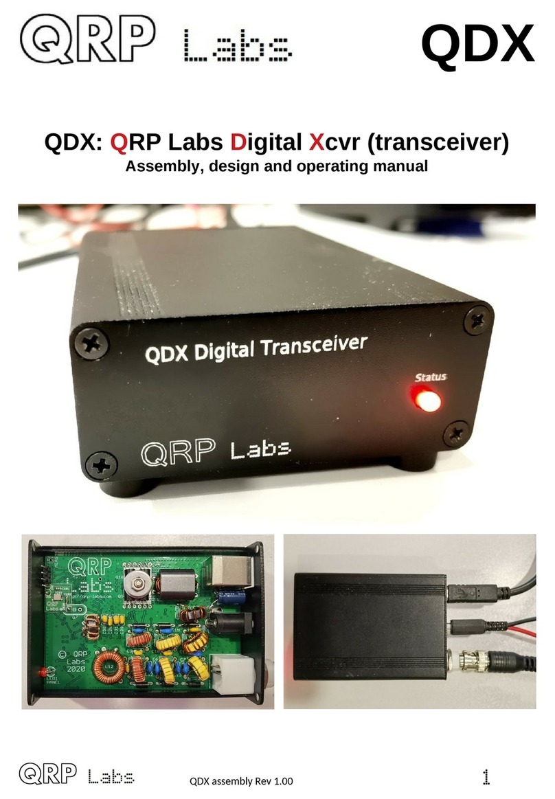
QRP Labs QDX User manual

QDX
QDX: QRP Labs Digital Xcvr (transceiver)
Operating manual, firmware 1. 4
1

Contents
!
"!#
$!%!
&!
'!!!
'(!!!
)
)*+
,%!
-."
/0!
+%$-
1
$!2)
"0 ,
# ,
'(!!,
)$34$!!,
,. /
-.5!!6!0/
2

1. Introduction
The QDX is a high performance, four-band 5W Digital modes transceiver with CAT control and
built-in SB sound card. QRP Labs presents QDX, a digital transceiver with a ratio of performance
to price not available until now.
•Four band 80, 40, 30 and 20m; 5 W from 9 – 10V supply
•Clean single signal output (zero residual carrier, zero unwanted sideband)
•Solid state PIN-diode switched Low Pass Filters and solid state Band Pass Filters
•Solid state transmit/receive switching
•High performance embedded-SDR SSB receiver using 110dB 24-bit stereo ADC chip
•Built-in SB sound card: 48ksps 24-bit stereo
•Built in SB Virtual COM port serial for CAT control
•Si5351A Synthesized local oscillator with better than 0.001Hz resolution and high precision
25MHz TCXO reference as standard
•Built-in signal generator
•Built-in suite of configuration and analysis tools
•Lifetime free firmware upgrades with QRP Labs Firmware pdate (QF ) bootloader for
easy firmware update on any OS with no extra software, or drivers, or programming
hardware
•All SMD components pre-installed by factory, only through-hole component soldering by the
kit constructor
•Receive current: 100mA; Transmit current 1.0 – 1.1A (9V supply, 5W output)
•Only three connectors: SB (audio and serial for CAT), Power and RF
•Optional smart aluminium extruded enclosure measuring just 89 x 63 x 25mm
No test equipment is required to build, align and operate this digi modes transceiver. There are no
alignment tasks.
Assembly of the transceiver is covered in a separate document, along with design details
(theoretical explanation) and performance measurements.
This document describes operation of QDX, and applies to the firmware version specified. This
manual will get you started with QDX and your WSJT-X or other digi modes software in minutes.
PLEASE READ THE BASIC ASSEMBLY AND USE INSTRUCTIONS IN
THIS MANUAL VERY CAREFULLY BEFORE APPLYING POWER TO
THE BOARD!
3

2 Operating instructions
Operation of the QDX transceiver is really simple. There are only three connections:
1. DC Power: use a regulated well-
smoothed DC supply of not more
than 12V; it should be capable of up
to 1A current supply. The connector
is a 2.1mm barrel type (outside
diameter 5.5mm).
2. RF: a standard BNC connector to
your antenna system
3. SB: SB type B connector (a
standard SB type A to B cable is
required) for Audio and CAT control.
Drivers
No additional drivers are required for operation with most Linux distributions, Apple Mac or MS
Windows 10.
For older versions of MS Windows, it may be necessary to install a driver for the serial port
because this driver is not on your computer already by default. This driver is available from the ST
Semiconductor website at https://www.st.com/en/development-tools/stsw-stm32102.html and is
applicable to 98SE, 2000, XP, Vista®, 7, and 8.x Operating Systems. There is a description for
installation on Windows 7/8 on the QRP Labs QLG2 page http://qrp-labs.com/qlg2 so if in doubt,
please check this.
Linux special note
On Linux systems, a particular problem can occur. When the QDX Virtual COM (Serial) connection
is detected, the PC thinks that a modem has been connected and starts trying to send it Hayes
AT-commands dating back to 1981, implemented on Hayes’ 300-baud modem. Yes! 40 years
ago…
The Operating System attempting to send AT commands to your QDX will certainly mess
everything up. Not least because when QDX receives a carriage return character, it will enter
Terminal Applications mode; this will send all sorts of characters back to the PC (as QDX thinks it
is now talking to a terminal emulator) and it will disable CAT command processing, so your PC digi
modes software will not be able to talk to QDX. Disaster.
To fix this you need to issue the following commands to disable ModemManager:
sudo systemctl stop ModemManager
sudo systemctl disable ModemManager
sudo systemctl mask ModemManager
This will permanently stop ModemManager. If for some reason, you actually DO need
ModemManager operational, for some other reason… well there IS a way to stop it just for QDX…
but Google will be your elmer on this!
4

WSJT-X configuration
Next it is necessary to set up WSJT-X to communicate with QDX. We will use WSJT-X as the
example, because it will be what most people are using. But other software will be identical (for
example JS8Call) or similar. There are two parts to the set-up – firstly to choose the right SB
Sound card, and secondly to set up the CAT communication so that WSJT-X can control the QDX
via the serial comm port.
Open the WSJT-X settings window (from the File menu) and select the Audio tab. Select “QRP
Labs QDX Transceiver” as the input and output sound card. The below screenshot shows how it
looks on my system, which is Linux (Xubuntu 18.04). It will look different on Windows, Mac and
perhaps other Linux distros but the basic idea will be the same… you should see something in the
drop-down which says something about QDX, and that’s the sound card to select.
5

Next click the “Radio” tab in the settings window, which sets up the CAT control communication.
The following four settings need to be changed, and are illustrated in the diagram below:
•Rig will be set to None by default, click the drop down and choose “Kenwood TS-440”
which should work well with QDX. On some other software, if you find that TS-440 is not
present in the list or does not work properly, you could try “Kenwood TS-480”. More details
about CAT and debugging any CAT problems are in another section of this manual, where
the CAT test terminal screen is described.
•The Serial Port drop-down must be set to the correct port where QDX is connected. On my
Linux system it is either “/dev/ttyACM0 or /dev/ttyACM1. On Windows systems it will be a
COM port numbered COM1, COM2 etc. nfortunately unlike the SB Sound, the serial port
name doesn’t contain the text “QDX”. If you are unsure which port to choose for QDX, the
easy way to find this is as follows. nplug QDX. Restart WSJT-X. Look in Settings -> Radio
and make a note of the list of serial devices. None of these are QDX (because you
unplugged it). Now close WSJT-X, plug in QDX, start WSJT-X and again look in Settings ->
Radio, and now you should see a newcomer in the list of available ports. The newcomer is
QDX!
•Note that none of the Serial Port Parameters need to be changed, leave them all at their
defaults. Even the baud rate 9600 is unimportant because it is irrelevant to the SB Virtual
COM Port which is a virtual port over SB, not a real physical serial port.
•Change the Poll Interval to 10 seconds, the default will be rather chatty with QDX which
probably is not a problem, but anyway I feel more comfortable with the less frequent polling.
QDX has no capability to alter its operating frequency for example by itself, it can only do so
at the command of WSJT-X over CAT; therefore the polling is actually redundant anyway.
•Change PTT Method from the default “VOX” to “CAT”. VOX means “voice operated
exchange” or “voice activated transmission”; the radio will automatically switch to transmit,
when incoming audio is detected. With PTT Method set to CAT, when WSJT-X wishes to
start a transmission, it will send an actual CAT command to QDX informing it to start the
transmission, before sending the audio. This CAT command causes QDX to switch from
Receive mode to Transmit mode (and back again afterwards). “CAT” is preferable to “VOX”
because if system sounds are accidentally routed to your “QDX” sound card as output, then
with VOX that will enable the QDX transmitter and try to transmit the sound.
•Now click the “Test CAT” button and after a few seconds, it should turn Green to indicate
successful communication with QDX.
6
NOTE 1: If you are using other software than WSJT-X or JS8Call, then QDX CAT commands
should still work with this software. If you encounter difficulties then it is possible that your software
is trying to communicate with QDX using CAT commands that are not supported by QDX. In the
section of this manual on the CAT Test utility (in the QDX Terminal applications), you will find a
listing of the CAT commands supported by QDX. Another useful utility is the log file, which will let
you record all CAT commands received and investigate any issues. If CAT commands are missing
for your application, QRP Labs can add support for them easily.
NOTE 2: As mentioned above, CAT control of transmit/receive switching is recommended. If you
INSIST on using VOX, QDX can support that. For example, you may be using a software
application which does not support CAT control of transmit/receive switching and can only use
VOX. In that case you should change the QDX transmit/receive switching mode from CAT to VOX
in the QDX terminal Configuration utility, which is described in the terminal applications section of
this manual.
7

NOTE 3: The Data Bits, Stop Bits, Handshake should not need to be changed; however several
users have reported that changing them to the settings shown in the orange box has resolved
some issues with CAT reliability on Windows Operating Systems.
WSJT-X “Pwr” Slider
The only other point to note is that WSJT-X should be operated with the power slider at the
maximum setting. This point is discussed further in the QDX design section which explains that
best accuracy in determining the audio tone frequency being sent by the PC, is when the Pwr is at
the maximum setting. There is no point to using any setting other than maximum, because QDX
only ever transmits at full power (5W), there is no way for it to transmit at a lower power output
under command of WSJT-X. If you wanted a lower power output, you would need to use a lower
supply voltage. Furthermore, QDX cannot be “over-driven” by too high volume, in the way that a
SSB transceiver could.
Therefore the “Maximum” setting for the Pwr slider is highly recommended, it is the optimum
setting for QDX operation.
8

QDX Status LED
The front panel of QDX contains a 3mm red Status LED. The operation of this LED is as follows:
•Quick flashing (flickering) for first 5 seconds after power up: if you disconnect power now,
then next time you power up, QDX will be in firmware update mode. During this five
seconds QDX is also operating normally in Receive mode. After five seconds, the LED will
go to a steady on (lit) state.
•Slow flashing: QDX is in firmware update mode (refer to the Firmware pdate procedure
section of this manual). If you did not wish to be in firmware update mode and have entered
firmware update mode inadvertently, simply power down QDX and re-apply power; QDX
will now be in normal operating mode again (quick flashing for the first five seconds, see
above).
•Steady LED on state: QDX is in normal Receive mode operation
•LED flashes 3 times in quick succession, repeating every 1 second: QDX is in normal
Transmit mode operation
•LED flashes 2 times in quick succession, repeating every 1 second: the PC host software
application is sending audio to QDX, and QDX is detecting and measuring the incoming
audio, however the volume is too low (refer to Troubleshooting section, below).
•LED flashes 1 time in quick succession, repeating every 1 second: the PC host software
application has activated PTT but the QDX is not detecting any audio signal from the PC
(refer to Troubleshooting section, below).
Operate!
Once CAT is configured and working, and the QDX sound card is chosen, just operate WSJT-X as
you would normally! You can choose the desired band 80m, 40m, 30m or 20m from the WSJT-X
screen and WSJT-X will communicate with QDX via CAT, to cause QDX to switch in the correct
filters.
This QDX manual is not the place to include tutorials on various digi mode operation or particular
application software such as WSJT-X, such guides are readily available and written very much
more thoroughly than I could hope to achieve!
9

3 Firmware Update procedure
On occasion QRP Labs may make available updated firmware for QDX, in order to deliver bug
fixes or functionality enhancements.
QDX contains a new firmware update procedure for STM32-series microcontrollers, called QF
(QRP Labs Firmware Update) which provides the following features:
•Easy – anyone can do the firmware update
•No additional hardware required: only a standard SB A-B cable (or micro- SB cable if
you have installed a micro- SB connector)
•No additional software required: just the standard file manager application that is already
available on any PC
•No drivers: no special drivers need to be installed, the existing drivers on any modern PC
operating system are used
•Works on any PC Operating System: and in the same way: Windows, Linux, Mac
•Secure: firmware files are published on the QRP Labs website and are encrypted using
256-bit AES encryption technology
Entering bootloader (firmware update) mode:
QDX provides two possible ways to enter firmware update mode:
1) On powering up QDX, you will see the QDX status LED flickers quickly for 5 seconds after
power up, then illuminates solidly. If you power down QDX during this 5 seconds, then apply
power again, QDX will now boot up in QF (Firmware pdate) mode.
2) Select the “ pdate firmware” menu option in the QDX Terminal (see subsequent section of
this manual). QDX will then enter firmware update mode.
In firmware update mode, the status LED flashes slowly.
Exiting bootloader (firmware update) mode:
QDX provides two possible ways to exit firmware update mode:
1) pdate the firmware! After updating the firmware, QDX will automatically reboot in normal
operating mode.
2) Power down QDX, and re-apply the power again. QDX will reboot in normal operating mode.
USB Flash memory stick emulation:
In the firmware update mode, the QDX pretends to be a SB Flash memory stick, having a
4MByte capacity and implementing a FAT16 file system. This virtual “Flash stick” contains two
files:
the firmware program file of the QDX microcontroller. You may read the file from QDX, or
write a new one, just by dragging files in your file manager application.
10

EEPROM contents: the QDX configuration and log file (if enabled). Again, you can read the
file from QDX or write a new one to QDX, simply by dragging files in your file manager
application.
On entering the Firmware update procedure, a pop-up window should appear on your PC. On my
system (Linux X buntu 18.04) it looks like this:
Click the OK button.
The File Manager window will then open, and on my system looks like this:
11

QDX appears as a removable SB Flash device named “QDX”, and the folder two files. The
firmware file in this example is named shows a single file which is the firmware version file,
1_00_001.QDX in this example. The EEPROM file is always named EEPROM.QDX. You can read
and write EEPROM files in order to make and restore backup copies of your configuration etc.
The firmware file name must not be longer than 8 characters, and cannot contain punctuation
or spaces; the file extension must be no more than 3 characters. This is because the file system
emulation is FAT16 and these are the specifications of the FAT16 format.
You may check the properties of the file and will note that it is a 119.5K file. QDX firmware images
are always a 119.5K file. The creation date and modification date etc. have not been set, because
it was important to minimize the size and complexity of the QF bootloader, in order to maximize
the space available to the application firmware.
You may copy the existing firmware file to another directory of your computer. Crucially, to do the
firmware update, all you need to do is copy the new firmware file to this QDX “Flash disk”.
Download the new firmware file from the QRP Labs website, unzip it, and simply drag it into the
folder where the existing firmware file version is shown. Or copy and paste it, however you wish.
The file on the QRP Labs website is a ZIPPED file, please be sure to unzip it to get the .QDX
file before copying it to QDX.
As soon as you copy the new file to the QDX QF “flash drive”, the QDX QF bootloader erases
the current program from its memory and installs the new one.
The QDX firmware is 256-bit AES encrypted and this means:
•The encrypted QDX firmware file will only work on a QRP Labs QDX board, it cannot be
installed on any other board, even one containing the same processor.
•No other firmware file will work on the QRP Labs QDX board except an official QRP Labs
encrypted QDX firmware file.
The procedure will vary slightly for different Operating systems but in all cases is just a simple
matter of copying the new firmware file to the emulated QDX QF SB Flash drive.
The above firmware update procedure works on ANY modern OS because the QFU
bootloader emulates a USB Flash memory stick with the USB Mass Storage Device (MSD)
class, for which drivers are already present.
The QF bootloader implements a SB device stack (Mass Storage Device class), emulated
FAT16 file system, Flash erase/write, and 256-AES encryption.
12

4 Terminal Applications
QDX provides a suite of applications which may be accessed via a Terminal emulator running on
your PC. These applications provide configuration utility, and various self-test tools. It is very
educational and interesting to experiment with these tools.
However, most QDX users need never use the terminal applications, it is not necessary for
ordinary operation of QDX with WSJT-X etc. The terminal applications are for the interested
user, or if you need to set up a particular configuration.
The terminal applications display everything as ASCII text in a 80 x 24 character window. It’s not
as polished as a dedicated graphical user interface software application for QDX would be.
However, it has the advantage of requiring no special software or drivers, and all the variations
that would have to be supported for different PC Operating Systems such as Mac, Windows and
Linux, software installation procedures etc. Instead, all the applications are hosted and coded in
the QDX itself. The terminal emulator is only used to display the results. This keeps things simple
and low maintenance. After all, the terminal applications are useful bonus features rather than
core QDX functionality.
4.1 PC terminal emulator
I use Linux (X buntu 18.04) and I’m using the PuTTY terminal emulator. There are numerous
other terminal applications which will work fine. You may have your own favourite. They are all
capable of correct operation with QDX in its terminal mode.
I start PuTTY using command line “sudo putty” then connect to QDX on /dev/ttyACM1. Again as
before (refer to the Operating Instructions for connecting to QDX using CAT on WSJT-X) it is
necessary to know which serial port is being used by QDX. There is also a guide to identifying the
serial port at http://qrp-labs.com/qlg2 (scroll down the page); or you could use WSJT-X.
Make sure WSJT-X is NOT running, when you connect to the QDX serial port using the
terminal emulator. Only one PC application at a time can connect to Virtual COM Serial
ports.
Set the size of the terminal window to 80 columns and 24 rows.
13

4.2 Entering terminal applications mode
Normally the QDX serial port is connected internally to the QDX’s CAT command interpreter. CAT
commands include text and numbers, each CAT command is terminated by a semicolon. CAT
commands never include a carriage return (enter).
Note that when the terminal is connected, you can actually type on your keyboard to send CAT
commands. For example, try typing FA; (just those three characters – no Enter at the end). The
text FA00007074000; will appear on the terminal. FA is the command to read or set VFO A, and
the result is 7.074 kHz, the default QDX startup frequency. HOWEVER, this is not a very
convenient or easy way to try out CAT commands, there is a CAT command testing application
which is much easier to use.
To switch to terminal applications mode, simply press the Enter key on your keyboard. Now the
terminal applications mode will appear in your terminal emulator window, as shown below. The
screen shows the QDX firmware version (coloured yellow at top left), and a list of applications
coloured white. You may use the cursor keys to move the highlighted application up and down in
the list, and press Enter to select an application. Any application can be quit by pressing Ctrl-Q
which returns the terminal to the main menu screen.
Operation of each of the applications will be described in detail in subsequent sections.
4.3 Exiting terminal applications mode
When exiting terminal applications mode, do not simply close the terminal emulator window. Doing
so will leave the QDX in terminal applications mode and it will not accept CAT commands. To
switch it back to CAT command mode, use the cursor keys to scroll down to the “Exit terminal”
option at the bottom of the list, and press Enter. The screen is now cleared, and QDX is back in
CAT command mode. Only then should you close the terminal emulator window.
14

4.4 Configuration
The configuration screen allows entry of various QDX configuration parameters. The default
values are suitable for the vast majority of operating use. The following paragraphs describe each
configuration setting in turn. se the up/down arrows to select the item you wish to edit. The
cursor is positioned at the last character of the value. Numeric values have a defined field length.
You can press the backspace key to delete the current entry in whole or in part, and type in the
new value. For non-numeric configuration parameters, you can use the left and right arrow keys to
choose between the available values.
TCXO Frequency
Default is 25000000 (25 MHz). This is the oscillation frequency of the QDX TCXO (Temperature
Controlled Crystal Oscillator) and is used for calculating Si5351A parameters for setting the
desired QDX operating frequency.
The supplied TCXO is a high precision component and will normally be found to be within (a one
standard deviation error of) +/- 5 Hz of the specified 25 MHz value. It is not normally particularly
necessary from an operating perspective, to have a more precise operating frequency than this.
Remember that the error is also scaled to the operating frequency. So a 5 Hz error at 25 MHz will
translate to a 2.8 Hz error at 14 MHz.
However the perfectionists among you may wish to calibrate your operating frequency precisely –
and this menu entry is for you!
To configure the correct TCXO reference frequency, you will need to measure your operating
frequency, deduce the error amount, and apply a correction to the TCXO frequency configuration
parameter.
15

As an example, suppose your transceiver is set to a SB “Dial Frequency” of 14.0956 MHz and
WSJT-X is set up to transmit WSPR at 1500 Hz audio offset. This should result in a transmission
frequency of 14.097100 MHz. But let’s suppose that you measure it accurately, and you find that it
is 3 Hz high, at 14.097103 MHz. Now what?
There’s an error of +3 Hz in your operating frequency. To work out the required correction to the
TCXO reference frequency configuration, calculate 3 Hz multiplied by a ratio of 25 MHz / 14.0971
MHz, which results in 3 Hz x 1.77 = 5.3 Hz.
Therefore you should increase the reference frequency by 5Hz. So move the highlight to the
TCXO frequency using the up/down cursor keys, then press the backspace key once, and type 5.
That will change the reference frequency to 25000005.
How about if you don’t have an accurate way of measuring your operating frequency? I have
developed tools for QRP Labs website to help you to use the WSPRnet reporting network to
determine your operating frequency quite accurately. To use these tools, simply use WSJT-X and
QDX to operate as a 20m WSPR reporter (receiver) for several minutes, then look at this page:
https://qrp-labs.com/images/wsprnet/rxerror.html
Look for your callsign in the list, which shows the error in your reception reports (operating
frequency error).
Alternatively, you may operate as a WSPR transmitter using WSJT-X and QDX, and the following
page will show your actual transmitting frequency:
https://qrp-labs.com/images/wsprnet/txfreq.html
Both of these QRP Labs pages are updated every two minutes. The analysis loads the last 5
minutes (approximately) of 20m WSPR reports from the WSPRnet website database. It cross-
references all the reports, analyzing the error of receiver stations by cross-referencing against
reports of the same transmitters by other stations. In this way calibration errors of all receiving
stations in the network are averaged out. The accuracy is generally within 1 or 2 Hz.
Sideband
This setting determines the demodulation sideband. Normally pper Sideband ( SB) is used for
all digital modes, and is the default setting. If you wish to use Lower Sideband (LSB) for some
reason, you can change it here. se the left and right arrow keys to change between LSB and
SB.
Default frequency
This is the default start-up frequency of QDX at power-on. It defaults to the 40m FT8 frequency
7.074 MHz. If you would like it to power up on a different frequency, you may edit this
configuration setting.
16

VOX
If you want to use VOX (Voice Operated Transmission) then set this parameter to ENABLE. Any
incoming audio from the PC will then operate the Transmit/Receive switch and be transmitted.
When the audio stops, QDX will switch back to Receive automatically. The problem with this is
that any system sounds on your PC, if the PC is configured to deliver these to the QDX SB
sound card, will operate the transmitter and be transmitted.
The default setting “DISABLE” requires a CAT command from the PC host application (WSJT-X
for example) in order to enable the transmitter. This is discussed in this manual in the operating
manual section, on setting up WSJT-X for QDX.
If you wish to use software that does not support CAT Transmit/Receive switching, this may be
one reason why you would want to enable VOX.
If using VOX, you will also need to disable the CAT timeout feature (see below).
Rise threshold
This is a percentage signal level of maximum, above which the transmitter will be keyed down
(switched on). Its purpose is to ignore very low amplitude audio signals at the start of a raised
cosine keying envelope, whose audio tone could be decoded inaccurately due to quantization
error. This is discussed further in the Design section of this manual in the Audio Frequency
Analysis section. The default value of 80% should be fine for all purposes. The value should not
be set too close to 99%, since higher frequency audio where the number of samples per cycle is
small, may not contain a value sufficient to trigger this threshold in every cycle.
Fall threshold
This is a percentage signal level of maximum, below which the transmitter will be keyed up
(switched off). Its purpose is to ignore very low amplitude audio signals at the end of a raised
cosine keying envelope, whose audio tone could be decoded inaccurately due to quantization
error. This is discussed further in the Design section of this manual in the Audio Frequency
Analysis section. The default value of 60% should be fine for all purposes. The value should not
exceed (or be close to) the Rise threshold parameter, otherwise the transmitter will be repeatedly
keyed on and off falsely.
Minimum cycles
This parameter specifies the minimum number of audio cycles to use, in the measurement of
audio cycle period, for audio frequency calculation. This parameter is used in conjunction with the
Minimum samples parameter: both conditions must be satisfied in order for an audio frequency
measurement to be completed. This parameter is discussed further in the Design section of this
manual in the Audio Frequency Analysis section. The default value of 1 should be fine for all
purposes.
Minimum samples
This parameter specifies the minimum number of audio samples to use, in the measurement of
audio cycle period, for audio frequency calculation. This parameter is used in conjunction with the
17

Minimum samples parameter: both conditions must be satisfied in order for an audio frequency
measurement to be completed. This parameter is discussed further in the Design section of this
manual in the Audio Frequency Analysis section. The default value of 480 should be fine for all
purposes.
Bearing in mind that there are 48,000 audio samples per second, a value of 480 specifies a
minimum 0.01 second audio measurement period. In other words, there will be 100 measurements
of the audio frequency, per second, in this default configuration. This is sufficient to ensure that
high audio frequencies are measured accurately. In the unlikely event that frequencies below
100Hz need to be measured, the “Minimum cycles” value (1) will ensure that a longer
measurement period is used, to measure one cycle.
Discard cycles
This parameter specifies the number of audio cycles (zero crossings) which are ignored, when
audio is first detected. The reason for this parameter is that in conjunction with the “Rise threshold”
parameter, it can be seen that the first audio cycle after the threshold is passed, is not a complete
cycle. The following zero crossing therefore needs to be discarded because its period
measurement will be too short. The default value of 1 should be fine for all purposes.
IQ Mode
When IQ mode is enabled, the raw I and Q channels from the ADC are fed to the SB soundcard
directly, without any demodulation. This is suitable for people wishing to experiment with using
QDX as an SDR front end, with PC SDR software to demodulate I and Q channels. Remember
that there is a 12kHz IF offset applied to the VFO.
IQ Mode is not suitable for use with WSJT-X and other Digi mode programs.
Japanese band limits
When this setting is enabled, QDX will refuse to go into transmit mode if the specified synthesis
frequency is outside the Japanese band limits as specified in the JARL bandplans document
4278898'!48,*&8:%*;. This setting is useful for
Japanese license regulations compliance.
CAT timeout enable
When this setting is enabled, which it is by default, there is a timeout on Transmit; if the timeout
elapses and QDX does not receive a CAT command requesting it to switch back to Receive, then
it will automatically switch back to Receive.
This feature needs to be disabled if using VOX.
CAT timeout (sec)
The duration of the CAT command timeout (see above), in seconds.
18

4.5 Band configuration
The Band Configuration screen allows specification of all parameters that are handled per-band.
This screen is populated by default with the correct information to set QDX up for 5-band operation
on 80, 60, 40, 30 and 20m. However, if you wish to experiment with other bands (which will require
hardware modifications to Receiver Band Pass Filter and Transmitter Low Pass Filter component
values – for which you are on your own), then you may specify the other band parameters here.
There is space for 6 band configurations, which are arranged in columns in a table. You may move
from one column to the next by using the left/right arrow keys. se the up/down arrow keys to
move up and down the rows of each band specification column.
Remember that the number of characters in each setting is limited. To change the parameter
setting, you generally need to press the Delete key in order to delete the existing setting
characters, then enter new ones. The setting is stored in memory when you press the Enter key,
or one of the arrow keys to move to a different cell of the table.
As usual, press Ctrl-Q to quit the Band Configuration utility.
An explanation of the items in the Band Configuration screen follows:
Band name (m): Just a name for the band - this appears in all the other terminal applications such
as RF sweep, Transmitter test etc. to identify the set of settings corresponding to the band.
Audio gain (dB): 54 is the default and corresponds to the default value of 5,000 used in earlier
firmware versions in the main configuration screen. Valid values for the parameter are 0 to 99.
This makes it easy to choose a gain by band - which is often useful to get WSJT-X and JS8Call
perfectly happy on each band without needing to manually fiddle with gain adjustments when
changing bands. WSJT-X and JS8Call documentation recommends when the band is empty, the
signal strength meter on the bottom left should be at about +30dB.
19

Frequency min.: When you command a new frequency via CAT (from WJST-X etc), this is the
lower limit of this band definition.
Frequency center: The center frequency, which is the frequency of the vertical blue line seen in
the RF sweeps, the test frequency for AF sweeps, and is the frequency used by the Transmitter
Test screen. It doesn't have any other purpose and doesn't have to be the actual center (half way
between min and max).
Frequency max.: When you command a new frequency via CAT (from WSJT-X etc), this is the
upper limit of this band definition .
Sweep start: the start frequency for the RF sweep screen.
Sweep step: the step frequency for each point of the RF sweep plot screen.
BPF number ( -3): The Band Pass Frequency selection for this band.
LPF number ( -2): the Low Pass Frequency selection for this band.
Transmit: Enabled or Disabled, to allow or prevent transmission on this band.
PTT +5V positive: To enable or enable, for this band, whether +5V appears on the PTT connector
"ring" connection during transmit. This output is designed to directly interface with the QCX-series
50W Power Amplifier with a simple stereo jack audio cable. Remember, the 50W PA is a SINGLE
BAND amplifier so should only be used on the QDX with a single band, unless you are going to
build an external switched Low Pass Filter. Also remember that the 50W QCX-series amplifier is
designed for CW operation and not suitable for the high duty cycle of digital modes; therefore if
you wish to use this with the QDX transceiver, be sure to limit it to around 20-25W output power;
this will be achieved by using a 12V supply voltage to the 50W PA kit.
PTT grounded: To enable or disable, for this band, whether the PTT "tip" connection is grounded
during transmit. This PTT output is suitable for driving a typical grounded PTT type amplifier.
Please refer also to the hardware documentation (assembly manual) for more information on the
PTT connection, and the circuits driving it.
The PTT connector is a 3.5mm stereo jack connector. The “ring” connection can be configured as
a +5V PTT output, suitable for switching the QCX-series 50W amplifier. The “ring” connection is
also used on the 50W PA so only a standard stereo audio jack cable is required. The “tip”
connection can be configured as a grounding PTT output for connection to most other amplifiers.
Both the +5V-going and grounded PTT outputs (‘ring” and “tip” connections respectively) are
MOSFET open-drain outputs (utilizing P-channel and N-channel type MOSFETs respectively).
Both outputs have a 470-ohm resistor in series to protect them against accidental damage for
example, shorts to ground.
20
Other manuals for QDX
2
Table of contents
Other QRP Labs Transceiver manuals

QRP Labs
QRP Labs QCX 5W CW User manual

QRP Labs
QRP Labs QMX User manual

QRP Labs
QRP Labs QCX-mini CW User manual

QRP Labs
QRP Labs QDX User instructions

QRP Labs
QRP Labs QMX User manual

QRP Labs
QRP Labs QCX-mini User manual

QRP Labs
QRP Labs QDX User manual

QRP Labs
QRP Labs QCX Operating instructions

QRP Labs
QRP Labs QCX User manual