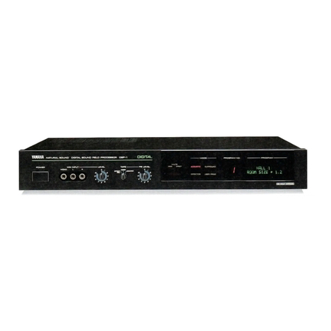
Yamaha DSP-1 User manual

rocessor.
PROGRAM
CONTENTS
BASIC
OPERATIONS
USER
PROGRAM
EDI
The
serial
number
is
located
on
the
rear
of
the
unit,
-Retain
this
Owner's
Manual
in
a
safe
place
for
future
reference.
oe
WARNING
2
aes
|
i
_
To
prevent
fire
or
shock
hazard,
do
not
expose
this
appliance
to
rain
USER
PROGRAM
TABLE
vee
neee
or
moisture.
TROUBLESHOOTING
....
|
Back
cover

CAUTION
RISK
OF
ELECTRIC
SHOCK
DO
NOT
OPEN
CAUTION:
TO
REDUCE
THE
RISK
OF
ELECTRIC
SHOCK,
DO
NOT
REMOVE
COVER
(OR
BACK).
NO
USER-SERVICEABLE
PARTS
INSIDE.
REFER
SERVICING
TO
QUALIFIED
SERVICE
PERSONNEL.
®
Explanation
of
Graphical
Symbols
The
lightning
flash
with
arrowhead
symbol,
within
an
equilateral
triangle,
is
intended
to
alert
you
to
the
presence
of
uninsulated
‘‘dangerous
voltage”
within
the
product's
enclosure
that
-
may
be
of
sufficient
magnitude
to
constitute
a
risk
of
electric
shock
to
persons.
The
exclamation
point
within
an
equilateral
triangle
is
intended
to
alert
you
to
the
presence
of
important
operating
and
maintenance
(servicing)
instructions
in
the
literature
accom-
panying
the
appliance.
SAFETY
INSTRUCTIONS
{1
Read
Instructions
—
All
the
safety
and
operating
instructions
should
be
read
before
the
appliance
is
operated.
2
Retain
Instructions
—
The
safety
and
operating
instructions
should
be
retained
for
future
reference.
3
Heed
Warnings
—
All
warnings
on
the
appliance
and
in
the
operating
instructions
should
be
adhered
to.
4
Follow
instructions
—
All
operating
and
other
instructions
should
be
followed.
5
Water
and
Moisture
—
The
appliance
should
not
be
used
near
water
—
for
example,
near
a
bathtub,
washbowl,
kitchen
sink,
laundry
tub,
in
a
wet
basement,
or
near
a
swimming
pool,
etc.
6
Carts
and
Stands
—
The
appliance
should
be
used
only
with
a
cart
or
stand
that
is
recommended
by
the
manufacturer.
{T
Wall
or
Ceiling
Mounting
—
The
appliance
should
be
mounted
to
a
wall
or
ceiling
anly
as
recommended
by
the
manufacturer.
8
Ventilation
—
The
appliance
should
be
situated
so
that
its
location
or
position
does
not
interfere
with
its
proper
ventilation.
For
example,
the
appliance
should
not
be
situated
on
a
bed,
sofa,
rug,
or
similar
surface,
that
may
block
the
ventilation
openings;
or
cabinet
that
may
impede
the
flow
of
air
through
the
ventilation
openings.
9
Heat
—
The
appliance
should
be
situated
away
from
heat
sources
such
as
radiators,
stoves
or
other
appliances
that
produce
heat.
10
Power
Sources
—
The
appliance
should
be
connected
to
a
power
supply
only
of
the
type
described
in
the
operating
instructions
or
as
marked
on
the
appliance.
11
Power-Cord
Protection
—
Power-supply
cords
should
be
routed
so
that
they
are
not
likely
to
be
walked
on
or
pinched
by
items
placed
upon
or
against
them,
paying
particular
attention
to
cords
at
plugs,
convenience
receptacles,
and
the
point
where
they
exit
from
the
appliance.
12
Cleaning
—
The
appliance
should
be
cleaned
only
as
recommended
by
the
manufacturer.
13
Nonuse
Periods
—
The
power
cord
of
the
appliance
should
be
unplugged
from
the
outlet
when
left
unused
for
a
long
period
of
time.
14
Object
and
Liquid
Entry
—
Care
should
be
taken
so
that
objects
do
not
fall
into
and
liquids
are
not
spilled
into
the
inside
of
the
appliance.
.
15
Damage
Requiring
Service
—
The
appliance
should
be
serviced
by
qualified
service
personnel
when:
A.
The
power-supply
cord
or
the
plug
has
been
damaged;
or
B.
Objects
have
fallen,
or
liquid
has
been
spilled
into
the
appliance;
or
C.
The
appliance
has
been
exposed
to
rain;
or
|
D.
The
appliance
does
not
appear
to
operate
normally
or
exhibits
a
marked
change
in
performance;
or
E.
The
appliance
has
been
dropped,
or
the
cabinet
—
damaged.
l

tt
a
16
Servicing
—
The
user
should
not
attempt
to
service
the
appliance
beyond
those
means
described
in
the
operating
instructions.
All
other
servicing
should
be
referred
to
qualified
service
personnel.
17
Power
Lines
—
An
outdoor
antenna
should
be
located
away
from
power
lines.
=
18
=
Grounding
or
Polarization
—
The
precautions
that
should
be
taken
so
that
the
grounding
or
polarization
of
an
appliance
is
not
defeated.
1
To
ensure
the
finest
performance,
please
read
this
manual
carefully.
Keep
it
in
a
safe
place
for
future
reference.
2
Install
your
unit
in
a
cool,
dry,
clean
place—away
from
—
windows,
heat
sources,
and
too
much
vibration,
dust,
moisture
or
cold.
Avoid
sources
of
hum
(transformers,
motors}.
To
prevent
fire
or
electrical
shock,
do
not
expose
to
rain
and
water.
3
Do
not
operate
the
unit
upside-down.
It
may
overheat,
possibly
causing
damage.
A
Never
open
the
cabinet.
If
a
foreign
object
drops
into
the
set,
contact
your
dealer.
5
Do
not
place
records
or
other
objects
on
top
of
the
unit;
this
will
block
the
ventilation
holes,
cause
the
internal
temperature
to
rise
and
may
result
in
a
failure.
6
Do
not
use
force
on
switches,
knobs
or
cords.
When
moving
the
set,
first
turn
the
unit
off.
Then
gently
disconnect
the
power
plug
and
the
cords
connecting
to
other
equipment.
Never
yank
the
cords.
T
Do
not
attempt
to
clean
the
unit
with
chemical
solvents;
this
might
damage
the
finish.
Use
a
clean,
dry
cloth.
8
Be
sure
to
read
the
“troubleshooting”
section
on
common
operating
errors
before
concluding
that
your
unit
is
faulty.
9
Do
not
connect
audio
equipment
to
the
AC
outlets
on
the
rear
panel
if
that
equipment
requires
more
power
than
the
outlets
are
rated
to
provide.
LDSk—1
10
This
equipment
generates
and
uses
radio
frequency
energy
and
if
not
installed
and
used
properly,
that
is,
in
strict
accordance
with
the
manufacturer’s
instructions,
may
cause
interference
to
radio
and
television
reception.
it
has
been
type
tested
and
found
to
comply
with
the
limits
for
a
Class
B
computing
device
in
accordance
with
the
specifications
in
Subpart
J
of
Part
15
of
FCC
Rules,
which
are
designed
to
provide
reasonable
protection
against
such
interference
in
a
residential
installation.
However,
there
is
no
guarantee
that
interference
will
not
occur
in
a
particular
installation.
If
this
equipment
does
cause
interference
to
radio
or
television
reception,
which
can
be
determined
by
turning
the
equipment
off
and
on,
the
user
is
encouraged
to
try
to
correct
the
interference
by
one
or
more
of
the
following
measures:
Reorient
the
receiveing
antenna
Relocate
the
DSP-1
with
respect
to
the
receiver
Move
the
DSP-1
away
from
the
receiver
Plug
the
DSP-1
into
a
different
outlet
so
that
the
DSP-1
and
receiver
are
on
different
branch
circuits.
—
If
necessary,
the
user
should
consult
the
dealer
or
an
experienced
radio/television
technician
for
additional
suggestions.
The
user
may
find
the
following
booklet
prepared
by
the
Federal
Communications
-
Commission
helpful:
“How
to
Identify
and
Resolve
Radio-TV
Interference
Problems”.
This
booklet
is
available
from
the
U.S.
Government
Printing
Office,
Washington,
DC
20402,
Stock
No.
004-000-00345-4.

Ei
ACCESSORIES
E
REMOTE
CONTROL
TRANSMITTER
The
following
three
accessories
are
provided:
|
In
this
unit,
most
operations
are
controlled
by
the
is
linear,
use
the
remote
control
transmitter
in
the
|
remote
control
transmitter
(RS-DSP1)
provided.
appropriate
area
taking
care
of
the
angles
to
the
Before
operating,
place
the
provided
batteries
into
the
==
remote
sensor
of
the
DSP-1
main
unit.
remote
contro!
transmitter
properly.
As
the
infrared
ray
N
BD
Within
7m
N,
KES
|
(About
23
feet)
“SSE
@
Remove
the
battery
compartment
cover.
@
After
placing
the
batteries,
replace
the
cover
until
the
click
®
O
sound
is
heard.
@
Place
two
batteries
^
in
correct
polarity.
Remote
control
transmitter
(RS-DSP1)
rear
view

Mi
BATTERY
REPLACEMENT
When
the
remote
controllable
distance
becomes
short,
batteries
are
exhausted.
Replace
two
batteries
with
new
ones.
Battery
cautions
Incorrect
use
of
the
battery
may
cause
leakage
or
explosion.
Be
careful
the
following
items:
When
replacing:
è
Place
the
batteries
in
correct
(+)
and
(—)
polarities
as
indicated
in
the
battery
compartment.
è
Do
not
use
the
old
battery
together
with
new
one.
®
Do
not
use
the
different
kind
of
batteries
at
the
same
time
even
though
in
the
same
shape.
Rechargeabie
batteries:
e
There
are
two
kinds
of
batteries
in
the
market:
rechargeable
and
non-rechargeable.
Read
the
caution
labeles
on
the
battery
carefully.
Use
with
the
remote
control
transmitter:
®
When
not
in
use
for
an
extended
period
of
time,
remove
the
batteries
from
the
remote
control
transmitter.
®
Replace
the
exhausted
batteries
earlier
in
good
time.
To
prevent
accident:
®
Never
disassemble,
heat
the
battery,
or
throw
into
the
fire.
Dispose
the
batteries
in
the
specified
places.
e
Do
not
connect
(short)
(+)
and
(~)
directly
with
the
metal
piece,
etc.
in
case
of
leakage:
Wipe
off
the
electrolyte
in
the
battery
compartment
completely
before
replace
with
the
new
batteries.
LSP

Speakers
may
be
placed
in
various
kinds
of
patterns
depending
on
the
extent
of
the
room
or
the
room
acoustic
characteristics.
The
placement
examples
shown
below
are
the
typical
patterns
for
effective
use
of
this
unit.
Place
the
speakers
on
the
most
suitable
position
for
your
listening
room
while
listening
actually.
|
Æ
6-CHANNEL
SYSTEM
|
3
E
4-CHANNEL
SYSTEM
Standard
placement
example
Standard
placement
example
|
|
Main
speaker
(For
source
sound
reproduction).
|
|
Main
speaker
(For
source
sound
+
effect
sound
reproduction)
|_|
Sub
speaker
(For
effect
sound
reproduction)
|_|
Sub
speaker
(For
effect
sound
reproduction)
(Place
the
sub
speakers
in
a
high
place.)
.
(Place
the
sub
speakers
in
a
high
place.)

@
PRECAUTIONS
ON
CONNECTIONS
_
@
Power
switch:
Turn
off
the
power
of
this
unit
and
other
equipment
before
making
connections.
®
Power
plug:
;
After
confirming
that
all
connections
are
correct,
insert
the
power
plug
of
this
unit into
the
AC
outlet.
®
Connection
cords:
Connect
all
the
audio
cords
with
correct
L
(left)
and
R
(right)
channels
firmly.
-
®
Installation:
If
this unit
interfere
with
the
other
equipment
(such
as
a
tuner
or
amplifier),
place
this
unit
away
from
the
other
units.

E
USING
WITH
SEPARATE
AMPLIFIERS
®
Set
the
FRONT
MIX
switch
of
this
unit
to
“OFF
6ch”,
@
When
only
two
speakers
are
used
as
the
sub
speaker,
the
FRONT
MIX
switch
setting
and
PROCESSING
jacks
connections
are
different.
Refer
to
page
10.
Set
this
switch
to
"OFF
6ch”.
en
L
e
Control
amplifier
ERONT
MIX
Power
amplifier
:
=
|
FRONT
e
.
OF
ON
6ch
4ch
PRE
OUT
INPUT
.
JMONO
GuT
BARD
FRONT
MX
AG
enna,
INPUT
OFF
CN
Main
speakers
|
BALANCE.
ol
LA
MAN
LEVEL
0O
c
r
LOW
PASS
ocg
“1008
;
fe:
00Hz
rear
panel
-
Sub
speakers
E
Q
|
Power
amplifier
Power
amplifier
MAIN
LEVEL
t
o
o
OdB
-iDJB
=
-
*To
drive
the
sub
speakers,
we
recommend
to
use
the
Set
this
switch
to
"—10dB”.
YAMAHA
M-35
power
amplifier
(optional).

DSr-1
@
USING
WITH
THE
INTEGRATED
AMPLIFIER
OR
RECEIVER
HAVING
PRE-OUT
AND
MAIN-IN
JACKS
@
Set
the
FRONT
MIX
switch
of
this
unit
to
“OFF
6ch”.
@
When
only
two
sub
speakers
are
used,
the
FRONT
MIX
switch
setting
and
the
PROCESSING
jack
connections
and
different.
Refer
to
page
10.
|
@
When
the
COUPLER
switch
is
provided
with
the
integrated
amplifier
or
receiver,
set
the
switch
to
ON
(SEPARATE).
When
the
PRE
OUT
jacks
and
MAIN
IN
jacks
are
shorted
with
jumper
pins,
unplug
the
jumper
pins
before
making
connections.
or
receiver
|
PRE
OUT
Main
speakers
MAIN
IN
Integrated
a
BB
nes
amplifier
Set
the
switch
to
“OFF
6ch”.
qe
Power
amplifier
FRONT
MIX
soe
N
AN
LLY
s
|
6ch
ách
MONO
OUT
FRONT
MX
FULE
BAND
rear
panel
Power
amplifier
MAIN
LEVEL
OdB
~iOdB
O
Z
ce
!
R
Set
this
switch
to
"—10dB".
“To
drive
the
sub
speakers,
we
recommend
to
use
the
C)
YAMAHA
M-35
power
amplifier
(optional).

=
USING
WITH
THE
INTEGRATED
AMPLIFIER
OR
RECEIVER
WITHOUT
PRE-OUT
AND
MAIN-IN
JACKS
@
Set
the
FRONT
MIX
switch
of
this unit
to
“OFF
6ch”.
@
When
only
two
sub
speakers
are
used,
the
FRONT
MIX
switch
setting
and
the
PROCESSING
jack
connections
are
different.
Refer
to
page
10.
O
Integrated
amplifier
|
or
receiver
Main
speakers
:
TAPE
PB
NE
O
l
op
Set
the
switch
to
“OFF
6ch”.
FRONT
MIX
Power
amplifier
7
FRONT,
rear
panel
INPUT
INPUT
Yr
3
rhe
FRONT
MIX
DSP
1
OFF
ON
Ga
ach
MAIN
LEVEL
e
c8
-'0¢c8
Sub
speakers
ay
oF
QO
i
Power
amplifier
|
C)
MAIN
LEVEL
Od8
@
Set
this
switch
to
“OdB”.
-i0dB
.
=-
*To
drive
the
sub
speakers,
we
recommend
to
use
the
YAMAHA
M-35
power
amplifier
(optional).

E
WHEN
A
PAIR
OF
SUB
SPEAKERS
ARE
USED
@
Use
only
the
PROCESSING
REAR
jacks.
Set
the
switch
to
“ON
4ch”,
=»
FRONT
MIX
ant
°
+
OFF
ON
G&ch
4ch
sa
OO
o
oN
MAN
eres
‘itz
C64
ipsa
For
setting
of
this
switch,
refer
to
pages
7~9.
©-
@
Set
the
FRONT
MIX
switch
of
this unit
to
“ON
4ch”
|
REAR
PROG
SSG
FRONT
TAPE
TAPE
PE
REC
OUT
)
|Q.
DSP-1
rear
panel
Power
amplifier
Sub
speakers
REAR
10

E
TAPE
DECK
CONNECTION
A
tape
deck
can
be
connected
to
the
TAPE
jacks
of
the
integrated
amplifier
or
receiver
(or
control
this
unit
to
record/play
the
source
of
effect
sound..
amplifier),
connect
the
tape
deck
to
these
jacks
as
Also
when
this
unit
is
connected
to
the
tape
jacks
of
shown
below.
Tape
deck
LINE
OUT!
LINE
IN
Polarity
indication:
s
i
,
The
polarity
indication
DSP-1
rear
panel
TAPE
PB}
TRECOUT
“
is
to
align
the
polarity
S
T
|
PARE
of
your
audio
system.
@
YAMAHA
cm
5
bii
Pera
h
T
nURTAG
4
tae
ot
iy
mat
PEROS
d
)
SED,
O
Q
a
IA
A
Monaural
To
AC
outiet
power
amplifier
AC
120V,
60
Hz
Up
to
200W
can
be
supplied
to
other
equipment.
-
The
supply
is
not
controlled
by
the
DSP-1’s
POWER
switch
.
Center
speaker
11
El
CONNECTION
OF
OTHER
EQUIPMENT
_%&
Connection
of
synthesizer
or
keyboard,
etc.
(MIX
INPUT
jacks)
Stereo
inputs
(L,
R)
and
mono
input
(MONO)
are
provided
for
variety
of
use.
*To
connect
a
microphone,
a
microphone
amplifier
is
required.
*
Connection
of
the
center
speaker
(MONO
OUT
terminals)
The
MONO
OUT
terminals
which
output
the
L-ch
+
R-ch
mix
signal
are
provided.
Use
the
LOW
PASS
terminal
when
adding
the
subwoofer
to
compensate
the
very
low
frequency
sound.
Use
the
FULL
BAND
terminal
when
adding
the
center
speaker
between
the
left
and
right
speakers
to
fill
up
the
localization
of
the
sound
image.
%*
The
AC
outlet
supplies
the
AC
power
(200W
max.)
to
the
other
audio
component.
This
AC
outlet
is
not
interlocked
with
the
POWER
switch
of
this
unit.

i
FRONT
PANEL
YAMAHA
NATURAL
SOUND
DIGITAL
SOUND
FIELD
PROCESSOR
DSP-1
MPEXINPUT
Ge)
YAMAHA
sr"
20
VOLTS
35WaTTS
.
60Hz
©
NIPPON
GAKKI
CO.,LTD.
&
©
MADE
IN
JAPAN
eman
a
Cornplies
with
the
limits
for
a
Class
B
computing
device
ursuant
to
ubpart
J
of
art
15
of
FCC
Rules.
Ji
RISK
OF
ELECTRIC
SHOCK
A.
ATTENTION
-
risque
DE
CHOC
ELECTRIQUE
NE
PAS
OUVRIR.
00
NOT
OPEN
WARNING
:
To
PREVENT
FIRE
OR
SHOCK
HAZARD.
DO
NOT
EXPOSE
THIS
APPLIANCE
TO
RAIN
OR
MOISTURE.
CAUTION
DSP
DIGITAL
PROGRAM
NO.
PROGRAM
MUTE
;
[Cs
ane
E
PB
LEVEI
MAN
GS
y
ACOUSTC
SURROUND
}
i
i
pa
mtg
{
USER
PROG!
g
go
fhe
ma
P
ARD
DOE
susrouns
INPUT
QUIPUT
ie
E
pee
FRONT
Mx
——
MaN
TOPE
PO:
PECOUT
UNSWITCHED
LEET
|
wij
EID,
TN
Ke
:
PB)
KB)
©
ee
Z
CFF
ON
BALANCE
í
C3)
aie
i
MAIN
LEVEL
Qe
T
@
o
©
IC
e
A
t
ous
$-
odg
it
12
Lob
©
G
O
O
0
12

E
FRONT
PANEL
@
POWER
switch
Turn
the
power
on
and
off.
When
the
power
is
turned
on,
the
last
program
before
the
power
has
been
turned
off
is
automatically
recalled
“For
several
seconds
after
the
power
is
turned
on,
the
sound
is
muted
by
the
protection
circuit.
®
MIX
INPUT
jacks
(MONO,
L,
R)
Used
to
mix
the
sound
signal
with
the
input
source
from
the
INF'UT
jacks
on
the
rear
panel.
Use
MONO
when
the
output
terminal
of
the
equipment
to
be
connected
is
monaural,
and
connect
L
and
R
jacks
when
the
equipment
is
stereo.
If
both
the
MONO
and
L/R
jacks
are
used
simultaneously,
the
level
from
the
MONO
jacks
may
be
lowered.
@
MIX
INPUT
LEVEL
control
Used
to
adjust
the
input
level
from
the
MIX
INPUT
jacks.
Turning
it
clockwise
increase
the
input
signal
level.
@
TAPE
selector
7
Selects
the
input
source
or
the
signal
recording
playback
with
the
tape
deck
connected
to
this
unit.
According
to
the
knob
position,
the
signal
path
changes
as
follows:
è
NORM:
Sound
field
effect
or
special
sound
effect
can
be
applied
to
the
input
source
from
the
rear
panel
INPUT
jacks
or
the
front
pane!
MIX
INPUT
jacks.
|
13
Input
jacks
INPUT
eS)
FRONT
—4
MIX
INPUT
Digital
signai
PROCESSING
processing
circuil
|
—
|
p>
CY
REAR
TAPE
PB
REC
OUT
Output
jacks
MAIN/“MONO
|
Signal
path
in
the
DSP-1
|
®
MONITOR:
Sound
field
effect
or
special
sound
effect
can
be
applied
to
the
signal
from
the
tape
deck
connected
to
this unit
Signal
path
in
the
DSP-1
Output
jacks
INPUT
MAIN/MONO
;
FRONT—4
MIX
INPUT
Es
dere
chao
PROCESSING
pi
g
REAR
—
TAPE
;
TAPE
PB
REC
OUT
è
EFFECT
REC:
The
effected
sound
(that
the
sound
field
effect
or
special
sound
effect
is
applied
to
the
input
source
from
the
INPUT
or
M!X
INPUT
jacks)
can
be
recorded
onto
the
tape
deck.
This
signal
is
output
only
from
the
REC
OUT
jacks.
Input jacks
Signal
path
in
the
DSP-1
INPUT
a
Digita)
signai
A
processing
circuit
a
+
Output
Jacks
MAIN/MONO
©
FRONT
MIX
INPUT
PROCESSING
EAR
——!
TAPE
PB
REC
OUT
@
TAPE
PB
LEVEL
control
Used
to
adjust
the
tape
sound
level
input
from
the
TAPE
PB
jacks
on
the
rear
panel.
-
@
Remote
sensor
Receives
the
remote
control
infrared
signal
from
the
remote
control
tramsmitter.
@
MUTE
indicators
(MAIN,
EFFECT)
Lights
when
the
MUTE
key
on
the
remote
control
transmitter
is
pressed
to
mute
the
sound.
®
MAIN:
Lights
when
the
MAIN
MUTE
key
is
pressed
to
mute
the
source
sound.
@
EFFECT:
Lights
when
the
EFFECT
MUTE
key
is
pressed
to
mute
the
effect
sound.
@
MODE
indicators
These
show
the
current
mode;
ACOUSTIC,
SURROUND,
EFFECTOR
or
USER
PROG
mode.
©
PROGRAM
NO.
display
Displays
the
selected
program
number.
@
PROGRAM
display
Displays
the
selected
program
name,
parameter,
etc.
*
The
display
panel
may
not
be
understandable
when
viewed
from
the
certain
direction.
See
it
from
the
front
when
operating.
|

=
REAR
PANEL
@
INPUT
BALANCE
control
Balances
the
left
and
right
effect
sound.
Normally
set
to
the
center
position.
@
INPUT
jacks
Inputs
the
signal
from
the
control
amplifier,
integrated
amplifier
or
receiver.
@®
MONO
OUT
jacks
(FULL
BAND,
LOW
PASS
fc:
200
Hz)
Outputs
the
left
and
right
mix
(MONO)
signal.
Use
these
jacks
when
the
left
and
right
speakers
are
too
separated
or
the
low
frequencies
are
unsatisfied.
è
FULL
BAND:
Outputs
the
full
range
signal.
@
LOW
PASS:
Outputs
the
low
frequency
signal
below
200
Hz.
@
FRONT
MIX
switch
Used
to
mix
the
source
signal
with
the
front
effect
Signal
sent
to
the
main
speakers.
When
the
switch
is
set
to
“ON
4ch”,
both
signals
are
mixed,
and
when
it
is
set
to
“OFF
6ch”,
they
are
output
independently.
@
When
used
in
4-channel
system
(with
4
speakers),
set
this
switch
to
the
“ON
4ch”
position.
The
source
sound
is
mixed
with
the
front
effect
sound
and
output
from
the
main
speakers.
@
When
used
in
6-channel
system
(with
6
speakers),
set
this
switch
to
the
“OFF
6ch”
position.
The
source
signal
is
output
from
the
MAIN
jacks
and
the
front
effect
signal
is
output
from
the-
PROCESSING
FRONT
jacks
separately.
@®
MAIN
LEVEL
switch
The
signal
level
output
to
the
MAIN
jacks
can
be
selected
between
0
dB
and
—10
dB
with
this
switch.
When
the
DSP-1
is
connected
between
the
control
amplifier
and
power
amplifier,
set
this
switch
to
"—10dB”.
When
the
DSP-1
is
connected
to
REC
OUT
and
TAPE
PB
jacks
of
the
integrated
amplifier
or
receiver,
set
this
switch
to
”0
dB”.
@
MAIN
jacks
These
jacks
output
the
signal
to
the
amplifier
or
receiver
which
drives
the
main
speakers.
(>
PROCESSING
jacks
(FRONT,
REAR)
These
jacks
output
the
signal
to
the
amplifier
which
drives
the
sub
speakers.
@D
TAPE
PB
jacks
These
jacks
input
the
signal
output
from
the
tape
deck.
@
REC
OUT
jacks
These
jacks
output
the
signal
to
the
tape
deck.
The
signal
output
from
these
jacks
can
be
selected
by
the
TAPE
selector.
@
AC
OUTLET
(UNSWITCHED)
This
supplies
the
AC
power
to
the
equipment
regardiess
of
the
POWER
switch
setting
of
this
unit.
*
Be
sure
to
check
the
power
consumption
of
the
equipment
to
be
connected
and
use
below
200
watts.
DSP
E
REMOTE
CONTROL
TRANSMITTER
23
f:
HAIE
I
f
f
DISCO
PAVILON
WHSELOFT
STADIUM
pLEMEHONC
ECHOROOM
__APTOHOHANGEE
$
i
L
TURN
R
TLAN
F-RA
L-R
PRESENCE
=]
<=
cS
SUR
D-
28
@)-
-®
DO
[eccey
surni)
ISITA
YAMAHA
REMOTE
CONTROL,
i
TRANSMITTE
RS-DS
:
14

DS
—1
@)
MEMORY
key
Used
to
store
the
program
modified
as
desired
into
the
user
program
area.
@
MODE
keys
Select
the
desired
mode
with
these
keys.
(See
table
below.)
When
the
mode
is
changed,
the
program
which
is
stored
in
the
same
program
position
as
the
previous
mode
is
called.
ACOUSTIC/SURROUND
mode:
Programs
for
sound
field
effect
or
surround
effect
are
preset.
SOUND
EFFECTOR
mode:
Programs
for
special
sound
effect
are
preset.
USER
PROGRAM
mode:
|
For
storing
the
user-modified
program.
i
HALL
1,
HALL
2,
HALL
3,
GHAMBER,
Münster,
CHURCH,
JAZZ
CLUB,
ROCK
CNCT
(CONCERT),
DISCO,
PAVILION,
WHSE
(WARE
HOUSE)
LOFT,
STADIUM,
PRESENCE,
SUR
(SURROUND)
1,
SUR
(SURROUND)
2,
OO)
SUR
(DOLBY
SURROUND)
ACOUSTIC;
SURROUND
DELAY
ST
(STEREO)
ECHO,
ST
(STEREO)
FLANGE
A,
B,
CHORUS
A,
B,
ST
(STEREO)
PHASING,
TREMOLO,
SYMPHONIC,
ECHO
ROOM,
PITCH
CHANGE
A,
B,
L
(LEFT)
TURN,
R
(RIGHT)
TURN,
F-R
(FRONT-REAR),
L-R
(LEFT-RIGHT)
SOUND
EFFECTOR
When
shipping,
the
same
programs
as
the
ACOUSTIC/SURROUND
mode
are
preset
at
the
factory.
The
program
modified
by
the
user
can
be
stored
in
this
area.
USER
PROGRAM
15
&®
PROGRAM
keys
Select
the
desired
program
with
these
keys.
After
selecting
the
desired
mode
with
the
MODE
keys,
select
the
desired
one
from
the
following.
6D
PARAMETER
key
.
Used
to
recall
the
program
parameter
(factor/element
to
determine
the
effect)
and
the
setting
value
‘displayed
on
the
panel.
Each
time
this
key
is
pressed,
the
parameter
is
changed
in
sequence.
Press
this
key
to
display
the
parameter
whose
value
is
to
be
changed.
@
TITLE
EDIT
key
Used
to
change
the
program
title
(name)
siöreð
in
the
User
Program
area.
(See
page
22.)
@
MUTE
keys
(MAIN,
EFFECT)
Mute
the
sound
from
the
speakers
with
these
keys.
@
MAIN:
When
this
key
is
pressed,
the
main
sound
is
muted
and
the
MUTE
MAIN
indicator
lights.
—
.
Also
the
signal
output
from
the
MONO
OUT
jack
is
canceled.
@
EFFECT:
When
this
key
is
weed
the
effect
sound
is
muted
and
the
MUTE
EFFECT
indicator
lights.
@
DEC
key,
INC
key
‘These
keys
are
used
to
change
the
parameter
value.
To
increase
the
value,
press
the
INC
key,
and
to
decrease
it,
press
the
DEC
key.
When
the
key
i
is
kept
pressing,
the
value
is
changed
continuously
and
stopped
at
the
minimum
or
maximum
point.
These
keys
are
also
used
to
change
the
program
title
(name)
stored
in
the
user
program
area.
(See
pages
20
and
22.)
@
BALANCE
key
(REAR,
FRONT)
Used
to
balance
the
effect
sound
between
the
front
and
the
rear
speakers.
When
the
REAR
key
is
pressed,
the
rear
effect
sound
level
is
increased
and
the
front
sound
is
decreased.
When
the
FRONT
key
is
pressed,
the
front
effect
sound
level
is
increased
and
the
rear
effect
sound
is
decreased.
When
one
of
the
BALANCE
keys
is
pressed,
the
indication
shown
below
is
displayed
on
the
PROGRAM
display
as
the
reference
for
adjustment.
EFFECT
BALANCE
R:
Rear
F:
Front
@:
Cursor
(This
position
shows
the
volume
balance
between
the
front
and
rear.)
%:
Percent
(This
figure
shows
the
volume
balance
between
the
front
and
the
rear.)

@
LEVEL
keys
(DOWN,
UP)
Used
to
adjust
the
volume
level
of
the
effect
sound.
è
DOWN:
When
this
key
pressed,
the
effect
sound
is
decreased.
@
UP:
When
this
key
is
pressed,
the
effect
sound
is
increased.
When
one
of
the
LEVEL
keys
is
pressed,
the
indication
shown
below
is
displayed
on
the
-
PROGRAM
display
as
the
reference
for
adjustment.
|
EFFEOI
LEVEL
BEER
Be
ri,
HERRE
|00%
=:
Cursor
(Number
of
lighting
cursor
shows
the
volume
level
of
the
effect
sound.)
%:
Percent
(Shows
the
effect
sound
level
in
figures.)
Note:
After
adjusting
the
parameter
value
or
level/balance
of
the
effect
sound,
recalling
the
other
program
resets
the
parameter
values
to
initial
settings.
To
keep
the
adjusted
value,
store
the
program
in
the
user
program
area.
(See
page
21.)
In
a
concert
hall,
the
extent
or
shape,
image
localization,
and
echoicness
or
anechoicness
can
be
appreciated
even
if
the
eyes
are
closed.
This
is
because
sound
reflections
from
all
directions
are
heard
besides
the
direct
sound
from
stage
(instruments
or
voices)
simultaneously.
Our
auditory
sense
can
recognize
the
extent
of
the
hall
by
the
time
difference
between
the
direct
sound
and
the
reflections,
the
shape
of
the
hall
by
the
directions
of
the
reflections,
and
the
echoic
or
anechoic
characteristic
by
the
attenuations
of
the
sound.
:
Therefore,
simulating
the
time
difference
or
direction
of
the
reflections
and
the
attenuating
time
may
reproduce
the
sound
field
of
an
actual
concert
hall.
As
sound
produced
by
performers
is
reflected
by
all
objects
in
the
hail,
it
is
heard
not
only
from
the
direct
front
but
also
from
the
sides,
rear
or
ceiling.
LSh-—1
These
reflections
cannot
be
reproduced
by
the
conventional
2-channel
(2-speaker)
system,
but
require
extra
speakers
to
reproduce
sound
reflection
(this
is
called
the
sub
speaker).
The
DSP-1
is
designed
to
reproduce
the
realistic
sound
field
experienced
in
a
concert
hall
in
a
normal
listening
room
by
simulating
sound
reflection
from
all
directions
based
on
actual
measured
data,
using
extra
speakers
surrounding
the
listener.
Furthermore,
the
digital
signal
processing
circuit
adopted
in
this
unit
can
be
used
to
produce
special
sound
effects,
such
as
combining
phase-difference
signals,
changing
pitch
or
changing
imaging
position
periodically.
.
16

17
HALL
4
HALL
2
HALL
3
CHAMBER..
Münster
CHURCH
JAZZ
CLUB
ROCK
CONCERT
DISCO
PAVILION
WAREHOUSE
LOFT
STADIUM
PRESENCE
SURROUND
1
SURROUND
2
DOLBY
SURROUND
Sound
field
such
as
a
wide
and
deep
grand
hall;
Suitable
for
reproducing
operates
or
orchestra
music.
.
Sound
field
such
as
a
medium-sized
hall
(smaller
than
that
of
HALL
1).
Suitable
for
reproducing
the
orchestra
music,
etc.
Sound
field
such
as
the
multi-purpose
hall
which
can
store
1000
people.
Deeper
ambience
is
obtained.
Sound
field
such
a
the
grand
ball
room
in
the
court.
Suitable
for
reproducing
chamber
music,
etc.
Sound
field
such
as
in
the
cathedral.
sound
field
such
as
in
the
church.
Suitable
for
reproducing
pipe
organ
music
or
church
music.
Sound
field
such
as
in
the
jazz
club.
Sound
field
with
tight
ambience,
suitable
for
rock
or
rock-related
music.
Sound
field
such
as
in
the
disco.
Sound
field
such
as
in
the
indoor
stadium.
|
|
Sound
field
such
as
in
the
concrete-built
warehouse.
Sound
field
such
as
in
the
stadium
or
open-air
theater.
Effect
sound
is
delayed
separately
and
reproduced
fram
the
front
and
rear
speakers.
Sound
field
applying
the
depth
to
the
screen.
Suitable
for
AV
sources.
Sound
field
applying
a
width
to
the
screen.
Suitable
for
AV
sources.
Used
to
reproduce
the
Dolby
Surround-encoded
movies.
ie
a
ie
ul
ACOUSTIC
SURROUND

Æ
SOUND
EFFECTOR
mode
1
DELAY
This
program
shifts
the
delay
time*
between
the
front/rear,
and
left/right
channels.
2
STEREO
ECHO
Shifts
the
delay
time*
between
the
left
and
right
channels
slightly
so
that
the
stereophonic
echo
effect
is
obtained.
3
STEREO
FLANGE
A
Effect
that
tone
is
varying
and
swirling
is
obtained.
4
STEREO
FLANGE
B
STEREO
FLANGE
A
has
faster
speed
and
light
swirling
effect
against
B.
oe
Ce
ie
Effect
that
sound
is
rolling
and
swaying
(drifting)
is
obtained.
&
CHORUS
B
CHORUS
A
has
faster
speed
and
deep
effect
against
B.
7
STEREO
PHASING
Effect
that
tone
is
varying
periodically
is
obtained.
8
TREMOLO
isd
ale
effect
obtained
by
CHORUS
is
multiplied
and
the
volume
change
is
9
SYMPHONIC
ibe
ch
effect
obtained
by
CHORUS
is
multiplied
and
the
timing
is
changed
10
ECHO
ROOM
Effect
such
as
in
the
echo
chamber
of
the
recording
studio
is
obtained.
11
PITCH
CHANGE
A
|
These
programs
are
used
to
change
the
pitch,
however,
initially
in
the
preset
—
program,
pitch
is
not
changed.
12
PITCH
CHANGE
B
|
(See
pages
28
and
29.)
13
PAN
L-TURN
__
|
Sound
image
is
turned
to
the
left.
14
PAN
R-TURN.
Sound
image
is
turned
to
the
right.
|
15
PAN
F-R
Sound
image
is
moved
from
the
front
to
the
rear
continuously.
16
PAN
L-R
Sound
image
is
moved
from
the
left
to
the
right
continuously.
*
Delay
Time:
The
time
difference
between
the
time
source
sound
is
heard
and
the
time
effect
sound
is
heard.
18

*
Confirm
that
all
the
components
are
connected
correctly
before
turning
the
power
on.
The
32
kind
of
programs
have
been
preset
in
this
unit.
Among
this,
16
present
programs
are
used
to
reproduce
the
sound
field
(ACOUSTIC/SURROUND
-
mode)
and
the
rest
16
presets
are
used
to
obtain
the
special
sound
effect
(SOUND
EFFECTOR
mode).
For
the
features
of
each
program,
refer
to
the
“Program
Contents”
on
page
17.
*
When
using
with
the
integrated
amplifier
having
pre-
out
and
main-in
terminals:
When
the
REC
OUT
selector
is
provided
When
the
TAPE
MONI-
TOR
switch
is
provided
Set
the
input
selector
Set
the
switch
to
ON.
to
TAPE.
E
OPERATION
1
Power
ON
Turn
the
power
of
this
unit
and
audio
system
on.
2
TAPE
SELECTOR
switching
®
When
playing
the
amplifier’s
input
source,
or
when
mixing
the
input
signal
with
the
signal
from
the
MIX
INPUT
signal,
set
the
TAPE
selector
of
this unit
to
the
“NORM”
position.
®
When
playing
the
tape
deck
connected
to
this
unit,
set
the
TAPE
selector
of
this
unit
to
the
“MONITOR?”
position.
-
For
example,
recall
the
HALL
1
program
in
the
ACOUSTIC/SURROUND
mode.
19
3
Mode
selection
Press
the
mode
key
(ACOUSTIC/SURROUND,
in
this
example)
on
the
remote
control
transmitter.
4
Program
Recall
Press
the
program
key
(HALL
1,
In
this
example)
on
the
remote
control
transmitter.
5
Source
selection
(When
playing
the
amplifier’s
input
source)
è
Using
the
separate
amplifiers:
Select
the
desired
source
with
the
input
selector
of
the
control
amplifier.
@
Using
the
integrated
amplifier
or
receiver
having
pre-out/main-in
jacks:
-
Select
the
source
with
the
input
selector
of
the
integrated
amplifier
or
receiver.
®
Using
the
integrated
amplifier
or
receiver
having
no
pre-out/main-in
jacks:
When
the
REC
OUT
selector
is
provided
When
the
TAPE
MONI-
TOR
switch
is
provided
Set
the
input
selector
to
the
desired
source.
Set
the
REC
OUT
SELECTOR
to
the
desired
source.
*
For
more
details,
refer
to
the
instruction
manual
provided
with
the
amplifier
or
receiver.
6
Start
to
play
the
desired
source.
7
Source
volume
adjustment
l
When
playing
the
amplifiers
input
source,
adjust
with
the
volume
control
of
amplifier.
When
playing
the
amplifiers
input
source
mixing
with
the
MIX
INPUT
signal,
adjust
the
volume
with
the
amplifiers
volume
control
and
the
MIX
INPUT
LEVEL
control
of
this
unit.
When
playing
the
tape
deck
connected
to
this
unit,
adjust
with
the
TAPE
PB
LEVEL
control
of
this
unit.
When
using
the
integrated
amplifier
or
receiver
having
no
pre-out/main-in
jacks,
adjust
the
volume
also
with
the
amplifiers
volume
control.
a
&
Balance
adjustment
Using
the
MUTE
key
(MAIN,
EFFECT)
of
the
remote
control
transmitter,
adjust
the
level
of
the
power
amplifier
so
that
the
source-only
volume
is
equal
to
the
volume
level
of
only
the
effect
sound.
*
When
the
volume
control
is
not
provided
with
the
amplifier
for
Source
reproduction,
set
the
MAIN
LEVEL
switch
on
the
rear
panel
of
this unit
to
the
“—10
dB”
position
to
lower
the
source
volume.
With
this
adjustment,
the
difference
of
the
volume
levels
between
speakers
having
different
sensitivities
or
amplifiers
having
different
gains
can
be
corrected.
When
the
sensitivity
is
different
between
the
front
and
rear
sub
speakers,
select
the
“DELAY”
program
in
the
SOUND
EFFECTOR
mode,
and
adjust
the
power
amplifier
to
this
unit
so
that
the
volume
level
of
the
front
sub
speakers
becomes
equal
to
that
of
rear
sub
speakers.
(In
the
ACOUSTIC/SURROUND
mode,
balance
between
the
front
and
the
rear
differs
in
each
sound
field
data.)
Other manuals for DSP-1
2
Table of contents
Other Yamaha Computer Hardware manuals
Yamaha
Yamaha MY8-SDI-ED User manual

Yamaha
Yamaha DX7 MiniMAX Manual

Yamaha
Yamaha DMP7 User manual

Yamaha
Yamaha R-100 User manual
Yamaha
Yamaha MEP4 User manual

Yamaha
Yamaha DX7-4X-EXP User manual

Yamaha
Yamaha MTX3 User manual

Yamaha
Yamaha DX7mega128 User manual

Yamaha
Yamaha PLG100-VH User manual

Yamaha
Yamaha PLG100-VL User manual

Yamaha
Yamaha GQ1031 User manual

Yamaha
Yamaha CobraNet MY16-C User manual

Yamaha
Yamaha PLG150-DX Quick start guide

Yamaha
Yamaha F1040 User manual

Yamaha
Yamaha DSP-1 User manual

Yamaha
Yamaha EMP100 User manual

Yamaha
Yamaha PLG150-PF User manual

Yamaha
Yamaha MMP1 User manual
Yamaha
Yamaha MEP4 User manual

Yamaha
Yamaha DME Designer User guide