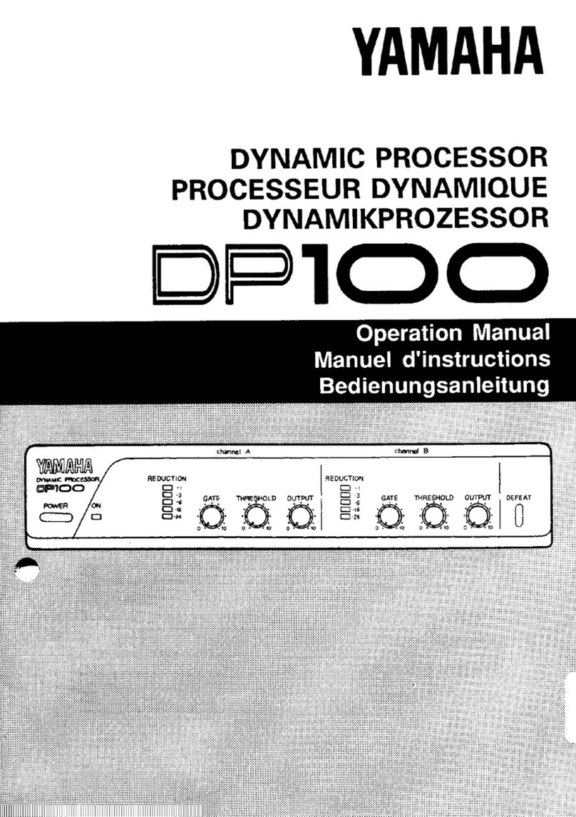
Yamaha DP100 User manual

YAMAHA
DYNAMIC
PROCESSOR
PROCESSEUR
DYNAMIQUE
DYNAMIKPROZESSOR
DP
TO
O
Operation
Manual
Manuel
d'instructions
Bedienungsanleitung

INTRODUCTION
Thank
you
very
much
for
purchasing
the
YAMAHA
Dynamic
Processor
DP100.
The
DP100
is
a
compact,
half-rack
sized
unit
which
comprises
a
limiter
circuit
and
a
noise
gate
cirucuit
in
stereo
configuration
with
two
independent
channels.
In
order
to
exploit
its
potential
to
the
fullest
and
for
trouble-free
operation
for
years
to
come
we
urge
you
to
read
this
manual
before
attempting
operation.
CONTENTS
Тизер:
2
PRECAUTIONS
..................................
2
NAMES
AND
FUNCTIONS
OF
PARTS
FRONT
PANEL
nee:
3/4
REAR
PANEL
tee
5
SPECIFICATIONS
`...
6
DIMENSIONS
.......
ees
6
SYSTEM
EXAMPLES
............................7/8
BLOCK
DIAGRAM.
................................
9

DYNAMIC
PROCESSOR
DPIOO
FEATURES
ETH
ө
Distortions
due
to
excessive
input
levels
can
be
controlled
by
the
limiter
circuit,
while
residual
noise
(when
there
is
no
input)
can
be
cut
by
the
integrated
noise
gate
circuit.
e
Reduction
indicators
permit
visual
confirmation
of
the
limiter
effect.
e
A
DEFEAT
switch
allows
bypassing
the
limiter
and
noise
gate
circuits
to
compare
source
sound
and
effect
sound.
e
Due
to
the
2-channel
configuration
throughout
this
unit
can
be
connected
to
stereo
equipment,
but
channels
can
be
also
used
separately.
e
INPUT
and
OUTPUT
offer
RCA
pin
jacks
and
phone
plug
jacks
for
connection.
A
LEVEL
switch
sets
the
input
level
to
-10
dB
or
-20
dB
to
allow
use
with
a
wide
range
of
PA,
recording
and
audio
equipment.
€
Due
to
its
compact
half-rack
size
and
light
weight
the
DP100
fits
anywhere
and
is
easy
to
transport.
PRECAUTIONS
e
Always
turn
the
power
switch
of
other
components
(power
amplifier,
etc.)
OFF
before
connecting
them
to
this
unit.
Also,
turn
this
unit
ON
first,
and
the
power
amplifier
last.
e
Use
only
the
YAMAHA
AC
adaptor
PA-1B
or
PA-5
or
the
power
supply
PW100.
Connecting
another
power
adaptor
with
different
polarity
or
voltage
may
cause
damage
to
the
DP100.
e
Avoid
using
the
unit
in
locations
like
the
following
to
prevent
damage
or
trouble.
*
Places
subject
to
direct
sunlight,
near
heating
devices,
etc.
Places
with
extreme
temperatures.
Excessively
humid
or
dusty
places.
Places
subject
to
strong
vibration.
*
*
*
e
Do
not
apply
force
to
switches
and
knobs.
e
Do
not
open
the
case
or
tamper
with
the
internal
circuitry
to
prevent
damage
and
the
danger.
of
electric
jolts.
e
Do
not
use
benzine,
thinner
or
solvents
for
cleaning
the
unit,
and
avoid
spraying
aerosol-type
insecticides
near
it
(they
may
cause
discoloration,
etc.)
e
After
reading
this
Operation
Manual,
keep
it
in
a
safe
place.

NAMES
AND
FUNCTIONS
OF
PARTS
REDUCTION
-1
C
-3
Os
GATE
THRESHOLD
OUTPUT
G
NL:
©
Power
switch
(POWER)
and
indicator
When
the
POWER
switch
is
ON
(
==-)
the
ON
indicator
lights
up.
Ө
Reduction
indicators
(REDUCTION)
When
the
limiter
circuit
is
activated
these
5
LEDs
display
the
reduction
level
for
the
input
signals.
@
Gate
level
control
(GATE)
This
control
determines
the
gate
level
for
the
noise
gate
circuit.
Sometimes
dis-
turbing
noise
and
hum
is
generated
when
there
is
no
input
signal.
To
limit
this
noise
set
the
gate
level
for
the
noise
gate
circuit
with
this
control
in
order
to
shut
off
input
signals
below
this
level
(noise
gate
closed).
Signals
above
the
set
gate
level,
however,
will
be
output
(gate
open).
Turn
this
control
when
there
is
no
input
singal
until
residual
noise
disappears.
*
The
more
you
turn
this
control
towards
"10"
the
higher
the
gate
level
will
become.
A
too
high
gate
level
will
prevent
a
naturally
fading
sound
and
pro-
duce
a
sudden
cut-off.
Therefore,
be
careful
when
adjusting
this
control.
Input
signal
|
When
passing
{
through
the
noise
\
d
gate
circuit
...
d
0
т
Су
š
©
ри
|
ра
|
^^
Gate
level
set
with
а
GATE
control
TIME
—
Gate
Gate
Gate
Gate
Il
G)
closed
open
closed
open

DYNAMIC
PROCESSOR
OPIOO
лг
MCA
EES
@
Threshold
level
control
(THRESHOLD)
This
control
adjusts
the
threshold
level
of
the
limiter
circuit.
An
excessive
input
level
will
not
only
cause
distortions
but
might
also
damage
the
speakers.
The
threshold
level
of
the
limiter
circuit
is
set
with
this
control
and
input
signals
above
this
level
will
be
compressed.
The
level
of
the
compressed
signal
will
be
dis-
played
by
the
REDUCTION
indicators
Ө
.
Set
this
control
to
a
suitable
position
by
checking
the
actual
sound
and
the
indicators.
When
passing
1
through
the
©
{
limiter
circuit
...
t
Ar
=
Threshold
level
iy
ш
>
=
>
D
sl
IL
oO
TIME
—>
TIME
—
@
Output
level
control
(OUTPUT)
Sets
the
ouput
level
of
the
signals
which
have
passed
through
the
limter
circuit
and
the
noise
gate
circuit.
When
the
DEFEAT
switch
@
is
pressed
ON
(
=)
this
control
determines
the
output
level
of
the
input
signal.
Turning
the
control
to
the
right
will
increase
the
output
level.
Q
Defeat
switch
(DEFEAT)
This
switch
determines
whether
signals
from
the
INPUT
jacks
will
be
processed
by
the
limiter
and
the
noise
gate
circuits
or
not.
When
this
switch
is
pressed
ON
(
=)
the
settings
of
the
GATE
level
control
Ө
and
THRESHOLD
level
contro!
@
will
have
no
effect.
In
this
case
the
input
signals
will
be
delivered
from
the
OUTPUT
jacks
with
the
level
set
by
the
OUT-
PUT
level
control
Ө.
When
the
switch
is
OFF
(mL
)
the
noise
gate
and
limiter
circuits
operate.
By
pressing
and
releasing
this
switch
you
can
check
the
effect
of
limiter
circuit
and
noise
gate
circuit.
*
Since
this
switch
applies
to
channel
A
and
B
simultaneously
you
can
not
switch
the
effects
ON/OFF
separetely
for
one
channel.
The
circuits
and
controls
are
identical
for
both
channels.
Due
to
this
2-chan-
nel
configuration
you
can
use
both
channels
A
and
B
together
or
connect
only
one
channel.

(
Rear
Panel
)
(3)
YAMANA
STEREO
OYNAMK
PROCESSOR
MODEL
ОРОО
DCI2V
BOmA
YAMAHA
CORPORATION
MADE
IN
JAPAN.
OUTPUT
CHA
=
с
“(ус
А
ot
2
M
ZA
(9)
Or
|
(0
ee
(6)
SS
@
Input
jacks
(INPUT
CH
A,
B)
These
RCA
pin
jacks
and
phone
jacks
are
the
input
terminals
of
the
unit.
Since
the
phone
jacks
have
priority,
no
signal
is
delivered
through
the
RCA
pin
jacks
when
there
are
plugs
connected
to
the
phone
jacks.
Ө
Input
level
selector
switch
(LEVEL
-20
dB/-10
dB)
To
select
the
nominal
input
level
for
the
input
jacks
between
-20
dB
and
-10
dB.
Set
it
according
to
the
connected
equipment's
output
level.
©
Output
jacks
(OUTPUT
CH
A,
B)
These
RCA
pin
jacks
and
phone
jacks
are
the
output
terminals
of
the
unit.
Both
can
be
used
at
the
same
time
(the
same
signal
is
output
through
both).
@
Output
level
selector
switch
(LEVEL
-20
dB/-10
dB)
To
select
the
nominal
output
level
of
the
output
jacks
between
-20
dB
and
-10
dB.
Set
it
according
to
the
connected
equipment's
input
level.
Q
Power
supply
terminals
(DC12V
IN,
OUT)
This
unit
requires
a
DC
+12
V
power
supply.
Connect
the
output
cable
of
an
AC
adaptor
or
a
cascade
cable
from
the
PW100
Power
supply
to
this
DC12V
IN
terminal.
*
Use
only
the
YAMAHA
AC
adaptor
PA-1B
or
PA-5
or
the
power
supply
PW100
for
AC
operation.
Using
an
AC
adaptor
other
than
these
might
cause
damage
to
the
unit.
The
DC12V
OUT
terminal
supplies
DC
+12
V
power
to
suitable
YAMAHA
compo-
nents
like
the
MV100,
the
Q100,
etc.
However,
the
total
current
consumption
of
this
unit
(80
mA)
and
connected
YAMAHA
components
must
be
within
the
maxi-
mum
current
supplied
by
the
AC
adaptor.
For
powering
more
than
two
devices
we
recommend
the
YAMAHA
power
supply
PW100
with
a
maximum
current
yield
of
2
A
or
the
YAMAHA
AC
adaptor
PA-5.
*
Don't
use
a
cascade
arrangement
for
supplying
power
to
the
Reverb
processor
R100.

DYNAMIC
PROCESSOR
DPIOO
SPECIFICATIONS
Input
terminals
Input
level
Input
impedance
Output
terminals
Output
level
Output
impedance
Gate
level
adjusting
range
Threshold
level
adjusting
range
Controls
Indicators
Power
Supply
Current
Consumption
Dimensions
(W
x
H
xD)
Weight
Standard
Accessory
*
OdB
=
0.775
Vrms
*
DIMENSIONS
:
RCA
pin
jacks
(CH
A,B),
phone
jacks
(CH
A,B)
Phone
jacks
have
priority
:
-
10
dB
(245mV)/-
20
dB
(77.5mV)
switchable
:
10
kOhm
:
RCA
pin
jacks
(CH
A,B),
phone
jacks
(CH
A,B)
:
-
10
dB
(245mV)/-
20
dB
(77.5mV)
switchable
:
600
Ohm
:
-
60
dB
—
-
70
dB
(at
—
20
dB)
:-
4
dB
—
–
44
dB
(at
-
20
dB)
:
POWER
switch,
GATE
level
volume
(CH
A,B),
THRESHOLD
level
volume
(CH
A,B),
OUTPUT
level
volume
(CH
A,B),
DEFEAT
switch,
input
LEVEL
selector
switch
(
—
20
dB,
-
10
dB),
output
LEVEL
selector
switch
(
-
20
dB,
—
10
dB)
:
5
LED
reduction
level
indicators
(7-1,
-3,
-6,
-
16,
-
24
dB:
CH
AB)
:
AC
adaptor
(DC
+12
V)
<OPTION>
:
80
mA
:
220
x
45.5
x
217
mm
(8-11/16"
x
1-13/16"
x
8-9/16")
:
1.1
kg
(2
lbs.
7
oz)
:
DC
Cascade
power
supply
cable
x
1
Specifications
and
design
are
subject
to
change
without
notice.
10
(3/8")
200
(7-7/8")
7
(1/4")
220
(8-11/16")
=
я
®
|
чс
=
UNIT
=
mm
(inch)
SE
`
=
ó

SYSTEM
EXAMPLES
1.
Use
with
recording
systems
The
noise
in
the
source
signals
mixed
down
by
the
MV100
will
be
cut
and
an
even,
clean
sound
for
recording
will
result,
while
distortions
due
to
excessive
input
levels
will
be
prevented.
Electric
guitar
Bass
guitar
+
+
GSP100
BSP100
Electronic
instruments
Microphone
GSP100
MIC
LINE
SA
MIXER
R
L
MV100
DYNAMIC
-40dB
IN
our
PROCESSOR
DP100
-10dB
MULTITRACK
CASSETTE
RECORDER
'
MT100
DC
IN
OOOO
оооо
is
ШЕЕ
ke
-
ШШ
234
POWER
AMPLIFIER
A100
SPEAKER
SYSTEM
$100
a,
CHB
CHA
(L)
(R)

DYNAMIC
PROCESSOR
DPIOO
.
Use
with
PA
systems
The
limiter
circuit
will
prevent
damage
to
the
speakers
due
to
excessive
input
levels.
Furthermore,
the
limiter
effect
will
produce
an
even
sound
while
the
noise
gate
circuit
will
cut
noise
so
that
you
can
obtain
a
balanced,
clean
sound.
€
The
examples
shows
two
cascade
connected
MV100s
offering
a
total
of
8
input
channels
Electric
guitar
Bass
guitar
+
+
GSP100
BSP100
Electronic
instruments
Microphone
Wali
ue
MIC
LINE
MIXER
MIC
LINE
MIXER
MV100
(MASTER)
Qin
MV100
(SUB)
Q
our
ST
DYNAMIC
PROCESSOR
-10dB
DP100
-10dB
POWER
AMPLIFIER
A100
_
SPEAKER
SYSTEM
S100
=.
SPEAKER
SYSTEM
$100
(L)
(R)
8

BLOCK
DIAGRAM
[e
D
EE
en
(V
HJ
SB
9W8S)
g
Н)
31Y9
Jo492jpu[
180403
980919)
|
|
|
L-------
4--
—------------
----
4------
-------------4
|
|
|
I
|
| |
|
NOI19n033
32933Y
|
|
indino
(8P02-/01-) (4P02-/01-)
Y
H2
Y
Н
1ndino
INdNI

m
ACCESSORIES/ACCESSOIRES/ACCESSOIRES
Rack
Mount
Kit
/
RK100,
RK200
Kits
de
montage
en
rack
/
RK100,
RK200
e
Rack-Einbausatz
/
RK100,
RK200
e
These
provide
space
for
19”
rack
mounting
of
YAMAHA
#100
series
units.
e
Ces
Kits
permettent
le
montage
en
rack
de
19"
d'appareils
YAMAHA
de
la
série
100.
e
Dienen
zum
Einbau
von
YAMAHA-Geraten
der
Serie
100
in
19
Zoll
Racks.
RK100
(1U-Type
/
Type
1U
/
Typ
1U)
e
Joint
Metal
/
JK100
e
Fixation
/
JK100
e
Verbindungsstück
/
JK100
e
An
accessory
for
setting
up
YAMAHA:
JK100
Я
Í
=
s=
#100
series
units.
|
e
Un
accessoire
servant
à
installer
plusieurs
appareils
YAMAHA
de
la
série
100.
e
Zubehór
zum
Aufeinanderstapeln
von
mehreren
YAMAHA-Geraten
der
Serie
YAMAHA
LG
aR
Bis
ORF
ORATION
mamatsu,
n
p
SC
ho
@
Printed
in
Joe
Other manuals for DP100
2
Table of contents
Other Yamaha Computer Hardware manuals
Yamaha
Yamaha DSP-1 User manual

Yamaha
Yamaha SPX2000 Editor User manual

Yamaha
Yamaha ME02R96 User manual

Yamaha
Yamaha F1040 User manual

Yamaha
Yamaha DB-SREV1 User manual
Yamaha
Yamaha DX7 DX-MAX(3)+ User manual

Yamaha
Yamaha RM-CR User manual

Yamaha
Yamaha mLAN8E User manual

Yamaha
Yamaha DX7mega128 Manual

Yamaha
Yamaha PLG100-VH User manual

Yamaha
Yamaha PLG100-VL User manual

Yamaha
Yamaha R-100 User manual

Yamaha
Yamaha GQ1031 User manual

Yamaha
Yamaha MTX3 User manual

Yamaha
Yamaha MMP1 User manual

Yamaha
Yamaha GC2020BII User manual

Yamaha
Yamaha DSP-A700 User manual
Yamaha
Yamaha PLG150-AN User manual

Yamaha
Yamaha DME Designer User guide
Yamaha
Yamaha PLG100-VL User manual