Yamaha RIVAGE PM10 User manual

EN
Operation Manual
Part 1: Overview
Part 2: Operations

CONTENTS
2RIVAGE PM10 Operation Manual
The manuals related to the RIVAGE PM10 system are organized as follows.
Paper manuals
RIVAGE PM10 System Setup Guide
This guide provides an overview of the RIVAGE PM10 system, and explains step by step how to set
up the system from connecting devices to producing sound.
Manuals for each device
The manual for each device describes part names and functions of that device. Each manual is
packaged with the corresponding device.
Online manuals
RIVAGE PM10 Operation Manual (this document)
This provides a detailed explanation of the screens and functions shown on the control
surface.
Part 1: Overview is concerned mainly with providing an overview and explaining the
concepts needed to understand the RIVAGE PM10 system. It contains knowledge and
information that you will need for planning the system.
Part 2: Operations explains specific procedures and operations of the system. It provides a
Function Map that lets you quickly access the information you need, as if using a
dictionary.
RIVAGE PM10 Editor Installation Guide
This guide explains how to install RIVAGE PM10 Editor.
NOTE
All manuals can be downloaded from the Yamaha website. If necessary, you can review
updated manual information, which is always posted on the Yamaha website.
http://download.yamaha.com/
How to use this operation manual
Since the RIVAGE PM10 Operation Manual (this document) is an electronic file (PDF file), it
provides links that you can click to view an item of interest, and allows you to search for terms.
Using the icon buttons
Icon buttons are located in the upper right of the operation manual.
CONTENTS ( ).............Press this button to view the table of contents.
FUNCTION MAP ( ) ...Press this button to view a function tree diagram. Since an item is
provided for each function screen, you can quickly access an
explanation for the function of interest.
Searching for terms
To search for a term, use the search function provided by the software you’re using to read this
document.
If you’re using Adobe Acrobat Reader DC, enter the term in the search bar and then press the
<Enter> key of your computer keyboard to find that term.
NOTE
The most recent version of Adobe Acrobat Reader DC can be downloaded from the following URL.
http://www.adobe.com/
Showing the next/previous view
When using Adobe Acrobat Reader DC, you can show the previous or next page that you viewed.
This is convenient when you have moved to a linked page and now want to return to the previous
page.
NOTE
If the show next/previous view button is not shown in the toolbar, you can hold down the <Alt> key on your
computer keyboard and use the <> <> keys to show the previous or next view.
About the Relevant Manuals

CONTENTS
3RIVAGE PM10 Operation Manual
About the Relevant Manuals ...........................................................................2
Component Structure ......................................................................................4
Control surface........................................................................................................5
About RIVAGE PM10 Editor....................................................................................7
DSP engine (DSP-R10) ...........................................................................................8
I/O rack (RPio622)...................................................................................................9
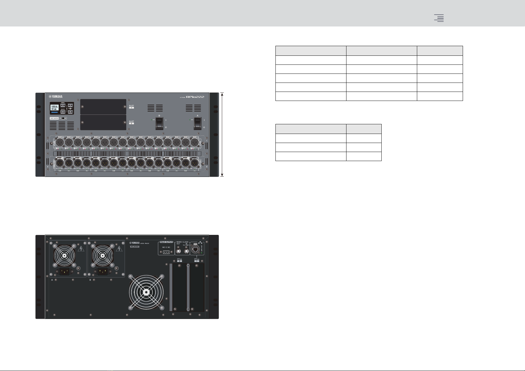
I/O rack (RPio222).................................................................................................10
RY card .................................................................................................................11
HY card .................................................................................................................11
TWINLANe Network ......................................................................................12
TWINLANe network ..............................................................................................12
Connecting a TWINLANe network card................................................................12
I/O and Routing Structure .............................................................................14
System-wide signal flow .......................................................................................14
Signal flow within the RPio622 ..............................................................................15
About Connections ........................................................................................16
Connecting a Computer ................................................................................17
Word Clock.....................................................................................................18
Word clock in the RIVAGE PM10 system..............................................................18
About the sampling rate converter (SRC).............................................................18
RIVAGE PM10 System Function List ..............................................................19
Input Channels...............................................................................................20
I/O unit section .....................................................................................................20
Mixing Engine section...........................................................................................21
Output Channels............................................................................................24
Mixing Engine section...........................................................................................24
MIX bus......................................................................................................24
MATRIX bus...............................................................................................26
STEREO bus ..............................................................................................27
I/O unit section......................................................................................................29
Delay Compensation ..................................................................................... 30
Monitor.......................................................................................................... 31
Cue ................................................................................................................. 32
Oscillator........................................................................................................ 33
Talkback ......................................................................................................... 34
DCA/Mute Groups......................................................................................... 35
GEQ/PEQ/Automixer ..................................................................................... 35
Plug-ins .......................................................................................................... 36
Plug-in type list......................................................................................................36
RTA (Realtime Analyzer)................................................................................ 38
Recording....................................................................................................... 40
2-track USB recorder ............................................................................................40
Multitrack recording and virtual sound check ......................................................40
Signal flow during a virtual sound check (VSC) ........................................42
MIDI/GPI........................................................................................................ 43
Customization................................................................................................ 44
Settings Files .................................................................................................. 45
Data handled by a settings file .............................................................................45
Conceptual Diagram of Memory................................................................... 47
Scene Memory ............................................................................................... 50
OVERLAY ........................................................................................................ 51
Other Convenient Functions ......................................................................... 52
Maintenance Functions ................................................................................. 52
Initialization ...........................................................................................................52
System log ............................................................................................................52
Calibration.............................................................................................................52
Contents (Part 1: Overview)

CONTENTS
Component Structure
4RIVAGE PM10 Operation Manual
The RIVAGE PM10 system uses a modular architecture, allowing you to flexibly design a system of
the appropriate size and structure.
The following components are included in the RIVAGE PM10 system.
Component Structure
Control surface DSP engine I/O racks RY cards HY cards
CS-R10
CS-R10-S
The control surface enables you to perform
general operations on the RIVAGE PM10 system.
(For details, refer to page 5.)
DSP-R10 (5U size)
The DSP engine handles mixing
and plug-in processing, and all
other audio processing for the
RIVAGE PM10 system.
(For details, refer to page 8.)
RPio622 (10U size)
RPio222 (5U size)
The I/O racks transfer analog and
digital audio signals to and from the
DSP engine.
(For details, refer to pages 9and 10.)
RY16-ML-SILK
This is a 16-channel mic/line input card.
It features SILK digital processing
technology that has been co-developed
by Rupert Neve Designs and Yamaha.
RY16-DA
This card features 16-channel analog
outputs.
RY16-AE
This card features 16-channel digital I/
Os that support the AES/EBU format.
Sampling rate converters are provided
on all inputs and outputs.
(For details on RY cards, refer to
page 11.)
HY256-TL
HY256-TL-SMF
This digital I/O card supports
TWINLANe (Yamaha’s
proprietary audio transfer
network protocol).
It can handle 256 channels and
be installed in the HY card slot
1.
HY144-D
This digital I/O card supports
the Dante digital audio network.
It can handle 144 channels and
be installed in the HY card slot.
(For details on HY cards, refer
to page 11.)

CONTENTS
Component Structure Control surface
5RIVAGE PM10 Operation Manual
Control surface
The CS-R10 control surface lets you control all functions of the DSP engine.
All audio signal operations such as mixing and routing, memory functions, and system settings can
be controlled.
The following functionality is provided.
• 12 x 3 bays + 2 (total 38) faders (CS-R10)
12 x 2 bays + 2 (total 26) faders (CS-R10-S)
• The full-function Selected Channel section acclaimed on Yamaha digital mixers
• A user interface that allows touch operation on large LCD panels
• Audio input/output connectors for connecting outboard gear or CD players (local I/O), and
control input/output connectors (MIDI/GPI)
• Two-track USB recorder function allows live recording, or playback of background music or sound
effects without requiring additional equipment
• Two internal power supply units provide redundant power
CS-R10
Top panel
Front panel
Rear panel
Jack list
Jack Connector
Number of jacks
OMNI IN (ANALOG) XLR-3-31 Type 8
OMNI OUT (ANALOG) XLR-3-32 Type 8
AES/EBU IN XLR-3-31 Type 4
AES/EBU OUT XLR-3-32 Type 4
TO ENGINE (Console Network) etherCON CAT5e 2
WORD CLOCK OUT BNC 1
MIDI IN DIN 5P 1
MIDI OUT DIN 5P 1
PHONES TRS 1/4" (6.35 mm) 4 (front)
TALKBACK XLR-3-31 Type 1
USB TYPE A USB 1 (top)
3 (rear)
RECORDING TYPE A USB 1
GPI D-Sub 25P (Female) 1
VIDEO OUT DVI-D 1
NETWORK (PC) etherCON CAT5 1
LAMP XLR-4-31 Type 4
AC INLET V-Lock Type 2
Slot list
Slot Number
MY CARD SLOT 2

CONTENTS
Component Structure Control surface
6RIVAGE PM10 Operation Manual
CS-R10-S
Top panel
Front panel
Rear panel
Jack list
Jack Connector
Number of jacks
OMNI IN (ANALOG) XLR-3-31 Type 8
OMNI OUT (ANALOG) XLR-3-32 Type 8
AES/EBU IN XLR-3-31 Type 4
AES/EBU OUT XLR-3-32 Type 4
TO ENGINE (Console Network) etherCON CAT5e 2
WORD CLOCK OUT BNC 1
MIDI IN DIN 5P 1
MIDI OUT DIN 5P 1
PHONES TRS 1/4" (6.35 mm) 2 (front)
TALKBACK XLR-3-31 Type 1
USB TYPE A USB 1 (top)
3 (rear)
RECORDING TYPE A USB 1
GPI D-Sub 25P (Female) 1
VIDEO OUT DVI-D 1
NETWORK (PC) etherCON CAT5 1
LAMP XLR-4-31 Type 3
AC INLET V-Lock Type 2
Slot list
Slot Number
MY CARD SLOT 2

CONTENTS
Component Structure About RIVAGE PM10 Editor
7RIVAGE PM10 Operation Manual
Bays
A channel strip section of 12 faders together with their touch screen section is called a “bay.”
The CS-R10 contains three bays; the CS-R10-S contains two bays. You can control these bays
independently.
About RIVAGE PM10 Editor
This Windows application software enables you to access the same functions that are available on
the control surface. You can use your computer to perform off-line editing by preparing the RIVAGE
PM10 system settings in advance, and to monitor and adjust those settings (on-line monitoring/
operation).
You can connect a computer with RIVAGE PM10 Editor installed (called PM10 Editor elsewhere in
this book) to a DSP engine or a control surface. If you connect it to a DSP engine, you can control
the entire system without a control surface. Therefore, in the event that the control surface
encounters a problem, you can still use your computer as a backup.
Details about the software are available on the following Yamaha Pro Audio website:
http://www.yamahaproaudio.com/
For information regarding how to download or install Editor, as well as its various setting details,
refer to the website listed above or to the Installation Guide attached to the downloaded software
program.
Bay L Bay C
Bay R
Selected Channel section

CONTENTS
Component Structure DSP engine (DSP-R10)
8RIVAGE PM10 Operation Manual
DSP engine (DSP-R10)
This is a 144-input, 72-mix, 36-matrix, 2-stereo DSP engine that performs all of the RIVAGE PM10
system’s audio processing such as mixing and plug-ins.
It provides four HY card slots and two MY card slots as well as control input/output connectors for
external equipment. Two power supply units are built-in, providing redundant power.
Front panel
Rear panel
* Support is planned in a future update.
* HY card slot 2 will be supported in a future update.
About the HY card slots
HY card slot 1 of the DSP engine is only for a TWINLANe network card. HY card slot 4 is used for
multi-track recording exclusively. HY card slot 3 can be used as general-purpose I/O. HY card slot 2
will be supported in the future. Each HY card slot 1 – 4 is 256-in/out.
5U size
Jack list
Jack Connector
Number of jacks
TO CONSOLE (Console Network) etherCON CAT5e 2
WORD CLOCK IN BNC 1
WORD CLOCK OUT BNC 1
NETWORK (PC) etherCON CAT5 1
NETWORK etherCON CAT5 1*
MIDI IN DIN 5P 1*
MIDI OUT DIN 5P 1*
TC IN XLR-3-31 Type 1*
GPI D-Sub 25P (Female) 1*
REMOTE D-Sub 9P (Male) 1*
FAULT OUTPUT Euroblock 3P 1
AC INLET V-Lock Type 2
Slot list
Slot Number
MY CARD SLOT 2
HY CARD SLOT 4*

CONTENTS
Component Structure I/O rack (RPio622)
9RIVAGE PM10 Operation Manual
I/O rack (RPio622)
This is an I/O rack for input/output of analog audio signals and digital audio signals of various
formats including AES/EBU to and from the DSP engine via a TWINLANe network card installed
in HY card slot 1. Six RY card slots and two MY card slots allow the I/O structure to be configured
flexibly. Two power supply units are built-in, providing redundant power.
Front panel
About the HY card slots
HY card slot 1 of the I/O rack is only for a TWINLANe network card. HY card slot 2 can be used as
general-purpose I/O. HY card slot 1 is 256-in/out, and HY card slot 2 is 128-in/out.
Rear panel
* Support is planned in a future update.
10U size
Jack list
Jack Connector
Number of jacks
WORD CLOCK IN BNC 1*
WORD CLOCK OUT BNC 1
NETWORK etherCON CAT5 1*
FAULT OUTPUT Euroblock 3P 1
AC INLET V-Lock Type 2
Slot list
Slot Number
RY CARD SLOT 6
MY CARD SLOT 2
HY CARD SLOT 2

CONTENTS
Component Structure I/O rack (RPio222)
10 RIVAGE PM10 Operation Manual
I/O rack (RPio222)
This is an I/O rack for input/output of digital audio signals to and from DSP engine. It provides two
RY card slots and two MY card slots, as well as two HY card slots. By limiting the number of RY card
slots to two, this rack features a compact size of 5U (half the size of an RPio622), offering great
flexibility in installation. Two power supply units are built-in, providing redundant power.
Front panel
About the HY card slots
HY card slot 1 on the I/O rack is for only a TWINLANe network card. HY card slot 2 can be used as
a general-purpose I/O. HY card slot 1 features 256-in/outs, and HY card slot 2 features 128-in/outs.
Rear panel
* Support is planned in a future update.
5U size
Jack list
Jack Connector
Number of jacks
WORD CLOCK IN BNC 1*
WORD CLOCK OUT BNC 1
NETWORK etherCON CAT5 1*
FAULT OUTPUT Euroblock 3P 1
AC INLET V-Lock Type 2
Slot list
Slot Number
RY CARD SLOT 2
MY CARD SLOT 2
HY CARD SLOT 2

CONTENTS
Component Structure RY card
11 RIVAGE PM10 Operation Manual
RY card
RY cards are 16-channel input/output cards. They support 16-channel input/output regardless of the
sampling frequency.
Mic/line analog input card (RY16-ML-SILK)
This is a 16-channel mic/line analog input card featuring a newly developed mic preamp and Rupert
Neve Designs’ “Silk” processing modeled in the digital domain. See page 20 for more about Silk.
Analog output card (RY16-DA)
This is a 16-channel analog output card. Level setting switches allow the maximum output level of
each channel to be switched between +15 dBu, +18 dBu, and +24 dBu. For details, refer to the
owner’s manual of the card.
AES/EBU input/output card (RY16-AE)
This is a 16-in/16-out AES/EBU format digital input/output card. Sampling rate converters are
provided on all inputs and outputs. For details, refer to the owner’s manual of the card.
HY card
The HY cards allow multiple channels of digital audio signals and control signals to be transferred.
TWINLANe interface card
This is a 256-in/256-out interface card that supports Yamaha’s proprietary TWINLANe audio
transfer network protocol.
HY256-TL
It uses multi-mode optical fiber cables such as Neutrik’s opticalCON DUO to allow transmission
between devices up to 300 meters apart.
HY256-TL-SMF
It uses single-mode optical fiber cables such as Neutrik’s opticalCON DUO to allow transmission
between devices up to 2km apart.
Dante interface card (HY144-D)
This is an interface card that supports the Dante digital audio network protocol created by Audinate.
It allows transfer of up to 144 channels of audio signals at a sampling frequency of 96 kHz.
Transmission up to 100 meters is possible using CAT5e or better Ethernet cable.
NOTE
• Please refer to the owner’s manual supplied with the host device for information on installing the I/O cards.
• For detailed information on I/O card settings, refer to the owner’s manual for the I/O card.
• For the latest information on which I/O cards can be used with the system, visit the Yamaha Pro Audio
website at:
http://www.yamahaproaudio.com/

CONTENTS
TWINLANe Network TWINLANe network
12 RIVAGE PM10 Operation Manual
TWINLANe is a proprietary Yamaha network protocol for transferring multiple channels of digital
audio and control signals simultaneously over a single cable.
TWINLANe allows low-latency transfer of up to 400 audio channels, and enables sharing between
all devices on the network. Input signals can also be shared between multiple DSP engines.
Ring topology allows redundancy that will keep the network running even if a cable fails.
TWINLANe network
* If the number of connected devices is much larger, or if the total length of all cables is too long, the listed
value may not apply.
NOTE
Use Neutrik opticalCON DUO multi-mode optical fiber cables. Optical fiber cable is easily damaged by
bending and pulling. Using cable that has a locking mechanism and strong insulation can help to reduce
trouble.
Connecting a TWINLANe network card
The TWINLANe network card can be used with the RIVAGE PM10 system.
To connect devices, first install a TWINLANe network card in an HY card slot of each device, then
use fiber optic cables to connect the TWINLANe network cards in a ring network topology.
NOTE
• Do not install both an HY256-TL-SMF and HY256-TL cards on a TWINLANe network.
•If you use an HY256-TL-SMF card, make sure that the total length of all cables is 6km or less.
TWINLANe Network
Transmitted data 400 channels of audio, control signals
Sampling frequency 44.1 kHz, 48 kHz, 88.2 kHz, 96 kHz
Network latency* 11 sample @ Fs = 44.1 kHz (0.25 msec)
11 sample @ Fs = 48 kHz (0.23 msec)
12 sample @ Fs = 88.2 kHz (0.14 msec)
12 sample @ Fs = 96 kHz (0.13 msec)
Bit-length 32-bit
Topology Ring
Cleaning
Correct communication might not be possible if debris and/or dust has adhered to the ends of
optical fiber cables or the connectors.
Clean the equipment regularly by using commercially available optical fiber cleaning products.
TWINLANe network card HY256-TL HY256-TL-SMF
Connection cable Multi-mode optical fiber
cable
Single-mode optical
fiber cable
Maximum cable length between
devices
300 meters maximum 2 km maximum
Maximum number of channels 256 in / 256 out

CONTENTS
TWINLANe Network Connecting a TWINLANe network card
13 RIVAGE PM10 Operation Manual
Ring connection
If a cable in the network breaks down for some reason, the signal will be automatically re-routed and
audio will flow without interruption. Even if a device in the network malfunctions, other working
devices will be able to continue communicating.
•Normalsituation
•Whenacableisbroken
Even if a cable is severed at one point, the signal will be re-routed automatically and
communication will continue without interruption.
.....
Device Device Device Device
TWINLANe
network card
TWINLANe
network card
TWINLANe
network card
TWINLANe
network card
OUT IN OUT IN OUT IN OUT IN
400 ch
OUT IN OUT IN OUT IN
400 ch
OUT IN OUT IN OUT IN

CONTENTS
I/O and Routing Structure System-wide signal flow
14 RIVAGE PM10 Operation Manual
The following diagram shows the signal flow of the entire RIVAGE PM10 system.
System-wide signal flow
I/O and Routing Structure
HY3
HY4 HY4
HY2*
MY1
MY2
MY1
MY2
CH
1-144
MIX 1-72 STEREO A/B MATRIX 1-36
MATRIX
1-36
MIX
1-72
STEREO
A/B
DIRECT OUT
PHONES OUTS
PLUG-INS
PLUG-INRACK
Max. 384 instances
GEQ/PEQ
48x 31bandGEQ
(96x Flex15GEQ)
(96x 8bandPEQ)
(1x 32Ch Automixer)
(1x 64Ch Automixer)
HY1
(HY256-TL)
HY1
(HY256-TL)
HY3
HY2*
HY1
(HY256-TL)
HY2
(HY144-D)
RY1
RY2
MY1
MY2
RY3
RY4
RY5
RY6
CUE/MONITOR/
PHONES
A/B
CUE A/B
CUE OUTS
MONITOR OUTS
CH REC OUT
MIX OUT
STEREO OUT
MATRIX OUT
MONITOR A/B
INSERT 1
INSERT 2
INSERT 1
INSERT 2
INSERT 1
INSERT 2
INSERT 1
INSERT 2
(for Inserts)
(for Inserts / Send-Return)
OSCILLATOR
RTA
TALKBACK
8x OMNI IN
4x AES/EBU
TALKBACK
2trk USB PLAYBACK
2trk USB RECORDER
MY1
MY2
I/O Rack
(RPio622)
Inputs HY1
(HY256-TL)
HY2
(HY144-D)
RY1
RY2
MY1
MY2
RY3
RY4
RY5
RY6
I/O Rack
(RPio622)
Outputs
Control Surface (CS-R10)
8x OMNI OUT
4x AES/EBU
4x PHONES
MY1
MY2
TWINLANe Network (400 ch)
DSP Engine (DSP-R10)
INPUT PATCH
OUTPUT PATCH
RECORDING
PATCH
(PLAYBACK IN)
RECORDING
PATCH
(REC OUT)
16
16
16
16
16
16
256
256
16
16
128
8
8
16
16
1
256
256
256
256 256
16
16
256
16
16
16
16
16
16
16
16
16
16
128
8
8
16
16
8
I/O Network I/O Network
Console Network Console Network
* HY card slot 2 of the DSP engine will be supported in a future update.

CONTENTS
I/O and Routing Structure Signal flow within the RPio622
15 RIVAGE PM10 Operation Manual
Signal flow within the RPio622
The following diagram shows the signal flow within the RPio622.
Mode 1
*1) In mode 1, all input signals (total 128 channels) of the RY slots and MY slots are always split for output to
the HY SLOT 2 output. The signal is output immediately after gain compensation.
*2) Specifies the number of channels that are output to the TWINLANe network (turn on/off in 16-channel
units for each slot).
Mode 2
*1) In mode 2, you can patch signals from the DSP engine to the HY SLOT 2 output via the TWINLANe
network.
*2) Specifies the number of channels that are output to the TWINLANe network (turn on/off in 16-channel
units for each slot).
HY SLOT 1 OUT
(256 ch max.)
RY SLOT 1 OUT
RY SLOT 2 OUT
RY SLOT 3 OUT
RY SLOT 4 OUT
RY SLOT 5 OUT
RY SLOT 6 OUT
MY SLOT 1 OUT
MY SLOT 2 OUT
HY SLOT 2 OUT
HY SLOT 1 IN
(256 ch max.)
RY SLOT 1 IN
RY SLOT 2 IN
RY SLOT 3 IN
RY SLOT 4 IN
RY SLOT 5 IN
RY SLOT 6 IN
MY SLOT 1 IN
MY SLOT 2 IN
HY SLOT 2 IN
TWINLANe Network (400 ch)
(Split Outs) *1
16 16 16 16 16 16 16 16 128
1-16
17-32
113-128
...
*2
16 16 16 16 16 16 16 16 128
HY SLOT 1 OUT
(256 ch max.)
RY SLOT 1 OUT
RY SLOT 2 OUT
RY SLOT 3 OUT
RY SLOT 4 OUT
RY SLOT 5 OUT
RY SLOT 6 OUT
MY SLOT 1 OUT
MY SLOT 2 OUT
HY SLOT 2 OUT
HY SLOT 1 IN
(256 ch max.)
RY SLOT 1 IN
RY SLOT 2 IN
RY SLOT 3 IN
RY SLOT 4 IN
RY SLOT 5 IN
RY SLOT 6 IN
MY SLOT 1 IN
MY SLOT 2 IN
HY SLOT 2 IN
TWINLANe Network (400 ch)
16 16 16 16 16 16 16 16 128
*2
*1
16 16 16 16 16 16 16 16 128

CONTENTS
About Connections
16 RIVAGE PM10 Operation Manual
The diagram below shows typical connections for the RIVAGE PM10 system. Equipment can be
combined in various ways to construct small systems or large systems.
• Connecting the control surface and DSP engine (Console Network)
A DSP engine (DSP-R10) has a dedicated connector (TO CONSOLE) for connection to the control
surface (CS-R10, CS-R10-S). You can connect a single control surface to one DSP engine. A network
created by the control surface and a DSP engine is called a “Console Network.” The Console
Network is connected as a ring. This provides redundancy for both audio signals and control signals.
• Connection between DSP engines and I/O racks (I/O Network)
A DSP engine and an I/O rack (RPio622, RPio222) are connected via a TWINLANe network, using
HY card slot 1. A network created by a DSP engine and an I/O rack is called an “I/O Network.”
The I/O Network is connected as a ring. One ring can connect up to two DSP engines and up to
eight I/O racks.
About the HY card slots
1HY card slot 1 of the DSP engine is only for a TWINLANe network card. HY card slot 4 is used
for multi-track recording exclusively. HY card slot 3 can be used as general-purpose I/O. HY
card slot 2 will be supported in the future. Each HY card slot 1 – 4 is 256-in/out.
2HY card slot 1 of the I/O rack is only for a TWINLANe network card. HY card slot 2 can be used
as general-purpose I/O. HY card slot 1 is 256-in/out, and HY card slot 2 is 128-in/out.
About Connections
I/O Rack
RPio622
RY card
MY card
DSP Engine
DSP-R10
Control Surface
CS-R10
MY cardMY card
HY1 HY2
I/O Rack Split Out
Additional Input
RY card
MY card
HY1 HY2
I/O Rack Split Out
Additional Input
I/O Rack
RPio622
RY card
MY card
HY1 HY2
I/O Rack Split Out
Additional Input
HY1 HY2 HY3 HY4
Additional
Input/Output
Multitrack (DAW)
Input/Output
or
Computer
(RIVAGE PM10 Editor)
Computer
(RIVAGE PM10 Editor)
I/O Rack
RPio622
I/O Network
Console
Network
Console
Network
or
DSP Engine
DSP-R10
Control Surface
CS-R10
MY cardMY card
HY1 HY2 HY3 HY4
Additional
Input/Output
Multitrack (DAW)
Input/Output
2
1 1
2 2
* HY card slot 2 will be supported in the future.
Console Network
Ethernet cable (CAT5e or better) (maximum 100 meters)
* etherCON connectors made by Neutrik are recommended.
I/O Network
Multi-mode optical fiber cable (maximum 300 meters between devices)
Single-mode optical fiber cable (maximum 2km between devices)
* LC Duplex connectors compatible with Neutrik’s opticalCON are recommended.
Ethernet connection
Ethernet cable (CAT5 or better) (maximum 100 meters)

CONTENTS
Connecting a Computer
17 RIVAGE PM10 Operation Manual
You can connect a computer with PM10 Editor installed to a DSP engine. To do so, connect the
computer to the NETWORK connector [PC] located next to the TO CONSOLE IN connector. Do
not connect it to the NETWORK connector located above the HY card slots.
Alternatively, you can use the NETWORK connector on the control surface. However, in this case,
please note that the computer will be unable to communicate with the DSP engine if the power to
the control surface is turned off.
NOTE
You can use only one instance of PM10 Editor per system. Do not connect two or more computers to
the system.
Connecting a Computer
DSP Engine
Control Surface
or Console Network

CONTENTS
Word Clock
18 RIVAGE PM10 Operation Manual
Word clock in the RIVAGE PM10 system
On a TWINLANe network, only one DSP engine is the master for one network. If two DSP engines
exist on one network, one is the master and the other is the slave.
The master clock on a TWINLANe network can be one of the following two choices: the DSP
engine’s internal clock (44.1 kHz, 48 kHz, 88.2 kHz, 96 kHz) or the external clock that is input to the
WORD CLOCK IN connector on the rear panel of the master DSP engine.
Since the slave DSP engine uses the word clock that is being sent over the TWINLANe network, HY
SLOT 1 is selected. If the clock is interrupted for any reason, the slave DSP engine can become a
substitute master. Since I/O racks always use the word clock that is being sent over the TWINLANe
network, there is no need to specify their word clock source.
About the sampling rate converter (SRC)
SRC is built into all input and output channels (one SRC for every two channels) of the AES/EBU
jacks on the rear panel of the control surface and of the RY16-AE. This allows digital signals that are
not synchronized to the RIVAGE PM10 system to be input and output.
SRC block diagram
The input SRC converts the signal to the system clock of the RIVAGE PM10 system.
The output SRC converts the signal to the specified internal clock source or to the same clock as the
input of the same channel.
* Only the corresponding input channels can be selected (if OUT1/2, then IN1/2). For example, IN7/8
cannot be used for OUT1/2.
Word Clock
INT
(INTERNAL)
INT
(INTERNAL)
HY1 HY1
WORD CLOCK IN WORD CLOCK IN
If INT (INTERNAL) or
WORD CLOCK IN is selected
The DSP engine will be the clock master for
the TWINLANe network
If HY SLOT 1 is selected
The DSP engine will be the clock slave of the
TWINLANe network
DSP engine
Internal
DSP
HY card
CLOCK OUT
HY card
CLOCK IN
(clock master
of the network)
Clock supplied to
TWINLANe
TWINLANe network
DSP engine
Internal
DSP
HY card
CLOCK OUT
HY card
CLOCK IN
(slave to the
network clock)
Clock supplied from
TWINLANe
TWINLANe network
SRC
CLOCK
OUT
INT 44.1k
INT 88.2k
INT 48k
INPUT
INPUT* INTERNAL
OUTPUT
SRC
DSP ENGINE
INT 96k
Clock extraction
AUDIO:
CLOCK:
INPUT
OUTPUT

CONTENTS
RIVAGE PM10 System Function List
19 RIVAGE PM10 Operation Manual
Click a function (blue text) to see a detailed explanation of that function.
RIVAGE PM10 System Function List
HY3
HY4 HY4
HY2*
MY1
MY2
MY1
MY2
CH
1-144
MIX 1-72 STEREO A/B MATRIX 1-36
MATRIX
1-36
MIX
1-72
STEREO
A/B
DIRECT OUT
GEQ/PEQ
48x 31bandGEQ
(96x Flex15GEQ)
(96x 8bandPEQ)
(1x 32Ch Automixer)
(1x 64Ch Automixer)
HY1
(HY256-TL)
HY1
(HY256-TL)
HY3
HY2*
HY1
(HY256-TL)
RY1
RY2
MY1
MY2
RY3
RY4
RY5
RY6
CUE/MONITOR/
PHONES
A/B
CUE A/B
MONITOR A/B
INSERT 1
INSERT 2
INSERT 1
INSERT 2
INSERT 1
INSERT 2
INSERT 1
INSERT 2
(for Inserts)
(for Inserts / Send-Return)
4x AES/EBU
TALKBACK
2trk USB Rec
MY1
MY2
HY1
(HY256-TL)
RY1
RY2
MY1
MY2
RY3
RY4
RY5
RY6
Control Surface (CS-R10)
4x AES/EBU
4x PHONES
MY1
MY2
DSP Engine (DSP-R10)
I/O Network I/O Network
Console Network Console Network
16
16
16
16
16
16
256
256
16
16
128
8
8
16
16
1
256
256
256
256
16
16
256
16
16
16
16
16
16
16
16
16
16
128
8
8
16
16
8
HY2
(HY144-D)
TWINLANe Network (400 ch)
INPUT PATCH
RECORDING
PATCH
(PLAYBACK IN)
8x OMNI IN
2trk USB PLAYBACK
8x OMNI OUT
CH REC OUT
MIX OUT
STEREO OUT
MATRIX OUT
PHONES OUTS
CUE OUTS
MONITOR OUTS
OUTPUT PATCH
2trk USB RECORDER
I/O Rack
(RPio622)
Outputs
HY2
(HY144-D)
OSCILLATOR
RTA
TALKBACK
PLUG-INS
PLUG-IN RACK
Max. 384 instances
RECORDING
PATCH
(REC OUT)
I/O Rack
(RPio622)
Inputs
* HY card slot 2 of the DSP engine will be supported in a future update.

CONTENTS
Input Channels I/O unit section
20 RIVAGE PM10 Operation Manual
I/O unit section
1ANALOG INPUT GAIN
This is the analog gain of the head amp.
2Silk
Allows you to add a natural sense of audio transformer compression and saturation.
This enhances the sense of depth and space, freshening the sound.
You can control the brilliance or power.
3GAIN COMPENSATION
Switches the gain compensation on or off for that channel.
If this is on, the signal level that is output from the I/O rack to the audio network (slot) remains
constant even if the HA analog gain is adjusted.
4Ø
Reverses the phase of the input signal.
5M/S DECODE
An M/S decoder is built in.
The M/S decoder is provided for adjacent odd- and even-numbered channels.
Input Channels
About “Silk”
Silk uses proprietary Yamaha “VCM technology” digital signal processing to faithfully
replicate the “Silk” processing that is built into numerous high-end analog audio devices
developed, manufactured, and sold by Rupert Neve Designs.
Based on the natural compression and saturation of audio transformers, a matter about which
Rupert Neve is especially passionate, the user can choose one of two characters, “Blue” or
“Red,” and use a continuously-variable “Texture” knob that allows effective control over the
tone and the accompanying overtones.
Silk allows effects such as the following.
• In addition to adding power and brilliance, you can recover the sense of air that tends to be
lost in the mix.
METER
GAIN
COMPENSATION
TRIM
ON
OFF
I/O Rack
RY Card Slot
DSP Engine
MY card
HY slot2
MY Card Slot
HY Card Slot
METER
METER
METER
A/B
input
A
B
VSC*
+48V MASTER
RY16-ML-SILK
+48V ON
ON
+48V
ON
+
-
ANALOG INPUT GAIN
SIGNAL
PEAK
12
3
RY16-AE
1
2
3
256
256
AD Silk
SRC
TWINLANe Network (400 Ch)
MS-
DECODE
METER
MS-
DECODE
HPF
HY
slot1
HY
slot1
INPUT PATCH
INPUT CHANNEL
* Virtual Sound Check
1
2
34
4
5
45
• The graceful and solid tone characteristic of an analog console can be obtained.
• Breathing and subtle pianissimos can be expressed in a lifelike way.
• Channel EQ and reverb become more effective.
• If this is used only on a small number of important channels, those parts will stand out from
the mix.
• If this is used on all channels, the mix will be given depth and three-dimensional character.
Red: Bright and lively
Blue: Rich and powerful
About the “Hybrid Mic Preamp” concept
This is a revolutionary mic preamp that uses digital signal processing to model and combine
the ultra-high-quality analog mic preamp representing the pinnacle of Yamaha’s “natural
sound” philosophy with Rupert Neve Designs’ “Silk” processing that allows you to freely
control the sound’s “depth, space, and air.” In the RIVAGE PM10 system, this is provided as
standard on the RY16-ML-SILK and on all the OMNI INPUT channels on the rear panel of
the CS-R10.
About gain compensation
The HA analog gain of the I/O rack can be controlled by the gain knob of the control surface,
but normally this will also change the input level to another DSP engine or recording device
that shares the input.
However if gain compensation is used to fix the gain within the I/O rack, the signal level that
is output to the audio network is kept constant. In other words, raising (or lowering) the
analog gain causes the compensation gain within the I/O rack to decrease (or increase).
Because the mixing input level can be operated using the digital gain within the DSP engine,
this allows the input level to be optimal for various routes used for different purposes.
Even if you turn gain compensation off again, the analog gain and compensation gain will
return to the settings they had when gain compensation was turned on, so the signal level that
is output to the audio network will not change.
In this way, you can adjust the analog gain for the optimal S/N ratio and use the digital gain to
adjust the input level independently.
Other manuals for RIVAGE PM10
5
Table of contents
Other Yamaha Mixer manuals

Yamaha
Yamaha n8 General instructions

Yamaha
Yamaha MG32/14FX User manual

Yamaha
Yamaha EM-95 User manual

Yamaha
Yamaha MC1204 User manual

Yamaha
Yamaha EM-300 User manual

Yamaha
Yamaha EM2820 User manual

Yamaha
Yamaha EM-100II User manual

Yamaha
Yamaha MV100 User manual

Yamaha
Yamaha EM-100 User manual

Yamaha
Yamaha M916 User manual

Yamaha
Yamaha PM-3000 User manual

Yamaha
Yamaha PM-170 User manual

Yamaha
Yamaha KM602 User manual

Yamaha
Yamaha EM-150II User manual

Yamaha
Yamaha MV100 User manual

Yamaha
Yamaha PM-210 User manual

Yamaha
Yamaha M7CL series User manual

Yamaha
Yamaha DSP1D User manual

Yamaha
Yamaha MM30 User manual

Yamaha
Yamaha M916 User manual