SILENT SG SERIES
8
2-3 DM Circuit Board
(Time required: About 4 minutes)
2-3-1 Remove the switch box front panel. (See procedure A-2-1)
2-3-2 Remove the switch box upper case. (See procedure A-2-2)
2-3-3 Remove the two (2) screws marked [121G] and two (2)
screws marked [122G]. The DM circuit board can then
be removed. (Fig. A-4)
2-4 DC-IN Circuit Board
(Time required: About 3 minutes)
2-4-1 Remove the switch box front panel. (See procedure A-2-1)
2-4-2 Remove the switch box upper case. (See procedure A-2-2)
2-4-3 Remove the two (2) screws marked [131G]. The DC-IN
circuit board can then be removed. (Fig. A-4)
2-5 Connector assembly-SW
(Time required: About 4 minutes)
2-5-1 Remove the switch box front panel. (See procedure A-2-1)
2-5-2 Remove the switch box upper case. (See procedure A-2-2)
2-5-3 Remove the DC-IN circuit board. (See procedure A-2-4)
2-5-4 Disconnect the connector of the connector assembly-
SW from the AM circuit board. While holding down the
hooks on the both sides of the seesaw switch, pull out
the seesaw switch and remove the connector assem-
bly-SW. (Fig. A-4)
2-3 DMシート(所要時間:約4分)
2-3-1 SB前パネルを外します。(A-2-1項参照)
2-3-2 SB上ケースを外します。(A-2-2項参照)
2-3-3 [121G]のネジ2本と[122G]のネジ2本を外して、DM
シートを外します。(図A-4)
2-4 DC-INシート(所要時間:約3分)
2-4-1 SB前パネルを外します。(A-2-1項参照)
2-4-2 SB上ケースを外します。(A-2-2項参照)
2-4-3 [131G]のネジ2本を外して、DC-INシートを外します。
(図A-4)
2-5 SW束線(所要時間:約4分)
2-5-1 SB前パネルを外します。(A-2-1項参照)
2-5-2 SB上ケースを外します。(A-2-2項参照)
2-5-3 DC-INシートを外します。(A-2-4項参照)
2-5-4 AMシートからSW束線のコネクタを抜きます。照光
シーソーSWの両横にあるツメを押さえながらパネルの
手前に押し出して、SW束線を外します。(図A-4)
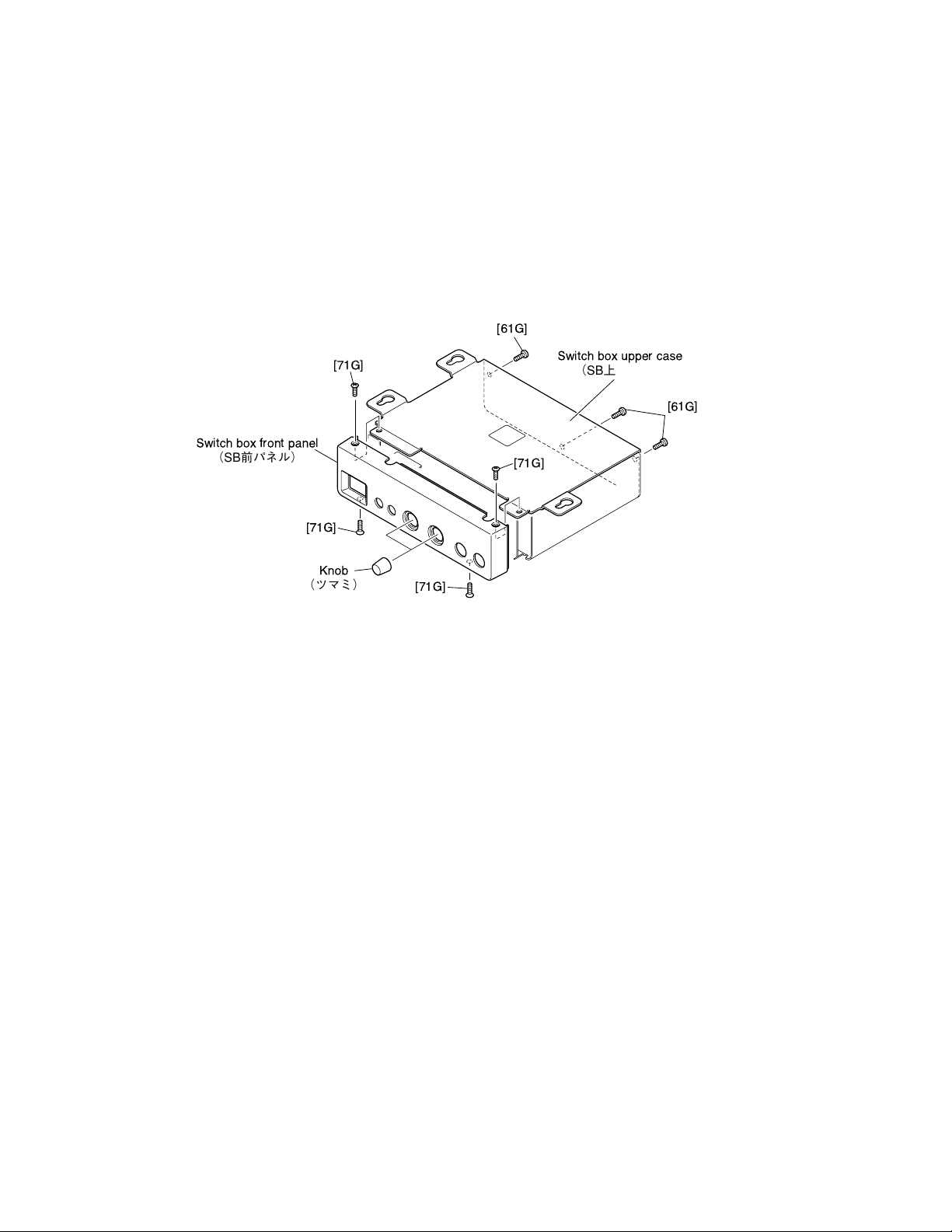
Fig.A-3(図A-3)
[61G]: BindHeadTappingScrew-S(Sタイト+BIND)3x6MFZN2B3(WE877800)
[71G]: FlatHeadTappingScrew-S(Sタイト+FLAT)3x6MFZN2B3(WE986900)
2. Disassembling the Switch Box Unit
2-1 Switch Box Front Panel
(Time required: About 1 minute)
2-1-1 Pull out the two (2) knobs for [VOLUME] and [REVERB],
and remove the four (4) screws marked [71G]. The
switch box front panel can then be removed. (Fig. A-3)
2-2 Switch Box Upper Case
(Time required: About 2 minutes)
2-2-1 Remove the switch box front panel.
(See procedure A-2-1)
2-2-2 Remove the three (3) screws marked [61G].The switch
box upper case can then be removed. (Fig. A-3)
2. SWBOXユニットの分解
2-1 SB前パネル(所要時間:約1分)
2-1-1 [VOLUME]・[REVERB]コントロール用のツマミ2個
を引き抜き、[71G]のネジ4本を外して、SB前パネルを
外します。(図A-3)
2-2 SB上ケース(所要時間:約2分)
2-2-1 SB前パネルを外します。(A-2-1項参照)
2-2-2 [61G]のネジ3本を外して、SB上ケースを外します。
(図A-3)
[71G]
[71G]
[71G]
Knob
(ツマミ)
Switch box front panel
(SB前パネル)
[71G]
[61G]
[61G]
Switch box upper case
(SB上ケース)