Yamaha 15F User manual

OWNER’S MANUAL
9.9F
15F
63V-28199-79-E0
U63V79E0.book Page 1 Friday, March 2, 2007 3:04 PM

Read this owner’s manual carefully before operating or working on your
outboard motor. Keep this manual onboard in a waterproof bag when boating.
This manual should stay with the outboard motor if it is sold.
U63V79E0.book Page 1 Friday, March 2, 2007 3:04 PM

Important manual information
EMU25103
To the owner
Thank you for choosing a Yamaha outboard
motor. This Owner’s Manual contains infor-
mation needed for proper operation, mainte-
nance and care. A thorough understanding of
these simple instructions will help you obtain
maximum enjoyment from your new Yamaha.
If you have any question about the operation
or maintenance of your outboard motor,
please consult a Yamaha dealer.
In this Owner’s Manual particularly important
information is distinguished in the following
ways.
The Safety Alert Symbol means AT-
TENTION! BECOME ALERT! YOUR SAFE-
TY IS INVOLVED!
WARNING
EWM00780
Failure to follow WARNING instructions
could result in severe injury or death to the
machine operator, a bystander, or a per-
son inspecting or repairing the outboard
motor.
CAUTION:
ECM00700
A CAUTION indicates special precautions
that must be taken to avoid damage to the
outboard motor.
NOTE:
A NOTE provides key information to make
procedures easier or clearer.
Yamaha continually seeks advancements in
product design and quality. Therefore, while
this manual contains the most current product
information available at the time of printing,
there may be minor discrepancies between
your machine and this manual. If there is any
question concerning this manual, please con-
sult your Yamaha dealer.
To ensure long product life, Yamaha recom-
mends that you use the product and perform
the specified periodic inspections and mainte-
nance by correctly following the instructions in
the owner’s manual. Any damage resulting
from neglect of these instructions is not cov-
ered by warranty.
Some countries have laws or regulations re-
stricting users from taking the product out of
the country where it was purchased, and it
may be impossible to register the product in
the destination country. Additionally, the war-
ranty may not apply in certain regions. When
planning to take the product to another coun-
try, consult the dealer where the product was
purchased for further information.
If the product was purchased used, please
consult your closest dealer for customer re-
registration, and to be eligible for the specified
services.
NOTE:
The 9.9FMH, 15FMH and the standard ac-
cessories are used as a base for the explana-
tions and illustrations in this manual.
Therefore some items may not apply to every
model.
EMU25121
9.9F, 15F
OWNER’S MANUAL
©2007 by Yamaha Motor Co., Ltd.
1st Edition, February 2007
All rights reserved.
Any reprinting or unauthorized use
without the written permission of
Yamaha Motor Co., Ltd.
is expressly prohibited.
Printed in Japan
U63V79E0.book Page 1 Friday, March 2, 2007 3:04 PM

Table of contents
General information .......................... 1
Identification numbers record.......... 1
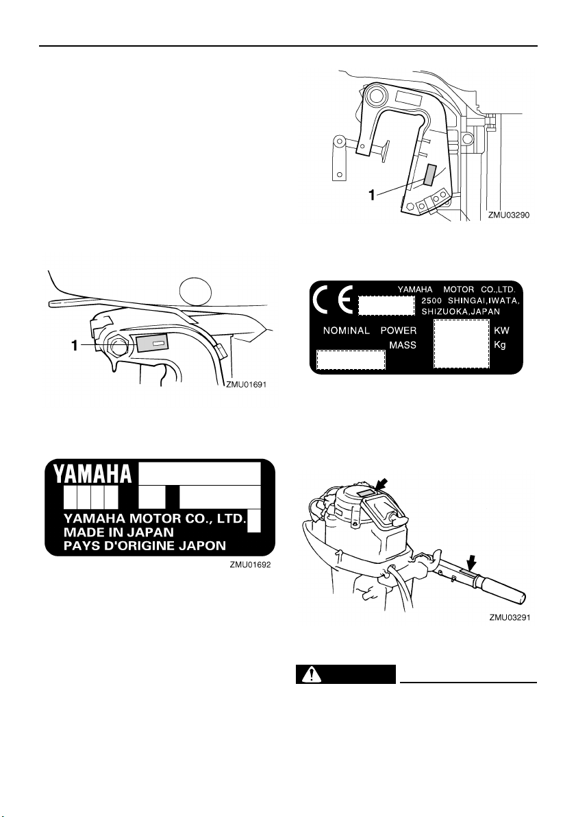
Outboard motor serial number ........... 1
EC label........................................... 1
Important labels............................... 1
Warning labels.................................... 1
Safety information............................. 3
Safety information ........................... 3
Rotating parts ..................................... 3
Hot parts............................................. 3
Electric shock ..................................... 3
Engine shut-off cord ........................... 3
Gasoline ............................................. 3
Gasoline exposure and spills ............. 3
Carbon monoxide ............................... 3
Modifications ...................................... 3
Boating safety ................................. 4
Alcohol and drugs............................... 4
Personal flotation devices .................. 4
People in the water............................. 4
Passengers ........................................ 4
Overloading ........................................ 4
Avoid collisions................................... 4
Weather.............................................. 5
Passenger training ............................. 5
Boating safety publications................. 5
Laws and regulations ......................... 5
Basic requirements ........................... 6
Fueling instructions ......................... 6
Gasoline ............................................. 6
Engine oil............................................ 6
Installation requirements ................. 6
Boat horsepower rating ...................... 6
Mounting motor .................................. 6
Propeller selection.............................. 7
Start-in-gear protection ................... 7
Basic components ............................8
Main components............................ 8
Fuel tank............................................. 8
Fuel joint............................................. 9
Fuel gauge ......................................... 9
Fuel tank cap...................................... 9
Air vent screw..................................... 9
Tiller handle ........................................ 9
Gear shift lever ................................... 9
Throttle grip ........................................ 9
Throttle indicator............................... 10
Throttle friction adjuster .................... 10
Engine shut-off switch ...................... 10
Engine stop button ........................... 11
Choke knob ...................................... 11
Manual starter handle....................... 11
Steering friction adjuster................... 12
Trim rod (tilt pin) ............................... 12
Tilt lock mechanism .......................... 12
Tilt support bar ................................. 12
Top cowling lock lever(s)
(turn type)...................................... 13
2-pin connector................................. 13
Operation ......................................... 14
Installation..................................... 14
Mounting the outboard motor ........... 14
Clamping the outboard motor........... 15
Breaking in engine ........................ 16
Gasoline and engine oil mixing
chart (50:1).................................... 16
Procedure for pre-mixed models ...... 16
Pre-operation checks .................... 17
Fuel .................................................. 17
Oil ..................................................... 17
Controls ............................................ 17
Engine .............................................. 17
Filling fuel and engine oil .............. 17
Filling fuel for portable tank .............. 17
Gasoline and oil mixing (100:1)........ 17
Operating engine .......................... 18
Feeding fuel (portable tank) ............. 18
Starting engine ................................. 19
Warming up engine....................... 21
Choke start models .......................... 21
U63V79E0.book Page 1 Friday, March 2, 2007 3:04 PM

Table of contents
Shifting .......................................... 22
Stopping boat ................................ 23
Stopping engine ............................ 23
Procedure......................................... 23
Trimming outboard motor.............. 23
Adjusting trim angle for manual tilt
models .......................................... 24
Adjusting boat trim............................ 24
Tilting up and down ....................... 25
Procedure for tilting up (manual tilt
models) ......................................... 26
Procedure for tilting down
(manual tilt models)....................... 26
Cruising in shallow water .............. 27
Cruising in shallow water
(manual tilt models)....................... 27
Cruising in other conditions........... 28
Maintenance..................................... 29
Specifications ................................ 29
Transporting and storing outboard
motor .......................................... 30
Clamp screw mounting models ........ 30
Storing outboard motor..................... 30
Procedure......................................... 31
Lubrication........................................ 32
Cleaning the outboard motor............ 32
Checking painted surface of motor... 32
Periodic maintenance.................... 32
Replacement parts ........................... 32
Maintenance chart............................ 33
Greasing........................................... 34
Cleaning and adjusting spark plug ... 35
Checking fuel system ....................... 35
Inspecting fuel filter .......................... 36
Cleaning fuel filter............................. 36
Inspecting idling speed..................... 37
Checking wiring and connectors ...... 37
Exhaust leakage............................... 37
Water leakage .................................. 38
Checking propeller ........................... 38
Removing propeller .......................... 38
Installing propeller ............................ 39
Changing gear oil ............................. 39
Cleaning fuel tank............................. 40
Inspecting and replacing anode(s) ... 41
Checking top cowling ....................... 41
Coating the boat bottom ................... 42
Trouble Recovery............................ 43
Troubleshooting ............................ 43
Temporary action in emergency ... 46
Impact damage................................. 46
Starter will not operate ..................... 46
Emergency starting engine............... 47
Treatment of submerged motor .... 48
Procedure......................................... 48
U63V79E0.book Page 2 Friday, March 2, 2007 3:04 PM

General information
1
EMU25170
Identification numbers record
EMU25183
Outboard motor serial number
The outboard motor serial number is stamped
on the label attached to the port side of the
clamp bracket.
Record your outboard motor serial number in
the spaces provided to assist you in ordering
spare parts from your Yamaha dealer or for
reference in case your outboard motor is sto-
len.
EMU25202
EC label
Engines affixed with this label conform to cer-
tain portions of the European Parliament di-
rective relating to machinery. Refer to the
label and the EC Declaration of Conformity for
more details.
EMU25382
Important labels
EMU25395
Warning labels
EMU25401
Label
WARNING
EWM01260
●Be sure shift control is in neutral before
starting engine. (except 2HP)
1. Outboard motor serial number location
1. EC label location
ZMU01696
U63V79E0.book Page 1 Friday, March 2, 2007 3:04 PM

General information
2
●Do not touch or remove electrical parts
when starting or during operation.
●Keep hands, hair, and clothes away from
flywheel and other rotating parts while
engine is running.
EMU25431
Label
WARNING
EWM01300
●This engine is equipped with a neutral
starting device.
●The engine will not start unless the shift
control is in neutral position.
U63V79E0.book Page 2 Friday, March 2, 2007 3:04 PM

3
Safety information
EMU33620
Safety information
Observe these precautions at all times.
EMU33630
Rotating parts
Hands, feet, hair, jewelry, clothing, PFD
straps, etc. can become entangled with inter-
nal rotating parts of the engine, resulting in se-
rious injury or death.
Keep the top cowling in place whenever pos-
sible. Do not remove or replace the cowling
with the engine running.
Only operate the engine with the cowling re-
moved according to the specific instructions in
the manual. Keep hands, feet, hair, jewelry,
clothing, PFD straps, etc. away from any ex-
posed moving parts.
EMU33640
Hot parts
During and after operation, engine parts are
hot enough to cause burns. Avoid touching
any parts under the top cowling until the en-
gine has cooled.
EMU33650
Electric shock
Do not touch any electrical parts while starting
or operating the engine. They can cause
shock or electrocution.
EMU33670
Engine shut-off cord
Attach the engine shut-off cord so that the en-
gine stops if the operator falls overboard or
leaves the helm. This prevents the boat from
running away under power and leaving peo-
ple stranded, or running over people or ob-
jects.
Always attach the engine shut-off cord to a
secure place on your clothing or your arm or
leg while operating. Do not remove it to leave
the helm while the boat is moving. Do not at-
tach the cord to clothing that could tear loose,
or route the cord where it could become en-
tangled, preventing it from functioning.
Do not route the cord where it is likely to be
accidentally pulled out. If the cord is pulled
during operation, the engine will shut off and
you will lose most steering control. The boat
could slow rapidly, throwing people and ob-
jects forward.
EMU33810
Gasoline
Gasoline and its vapors are highly flam-
mable and explosive. Always, refuel accord-
ing to the procedure on page 18 to reduce the
risk of fire and explosion.
EMU33820
Gasoline exposure and spills
Take care not to spill gasoline. If gasoline
spills, wipe it up immediately with dry rags.
Dispose of rags properly.
If any gasoline spills onto your skin, immedi-
ately wash with soap and water. Change
clothing if gasoline spills on it.
If you swallow gasoline, inhale a lot of gaso-
line vapor, or get gasoline in your eyes, get
immediate medical attention. Never siphon
fuel by mouth.
EMU33900
Carbon monoxide
This product emits exhaust gases which con-
tain carbon monoxide, a colorless, odorless
gas which may cause brain damage or death
when inhaled. Symptoms include nausea,
dizziness, and drowsiness. Keep cockpit and
cabin areas well ventilated. Avoid blocking ex-
haust outlets.
EMU33780
Modifications
Do not attempt to modify this outboard motor.
Modifications to your outboard motor may re-
duce safety and reliability, and render the out-
board unsafe or illegal to use.
U63V79E0.book Page 3 Friday, March 2, 2007 3:04 PM

Safety information
4
EMU33740
Boating safety
This section includes a few of the many im-
portant safety precautions that you should fol-
low when boating.
EMU33710
Alcohol and drugs
Never operate after drinking alcohol or taking
drugs. Intoxication is one of the most common
factors contributing to boating fatalities.
EMU33720
Personal flotation devices
Have an approved personal flotation device
(PFD) on board for every occupant. Yamaha
recommends that you must wear a PFD
whenever boating. At a minimum, children
and non-swimmers should always wear
PFDs, and everyone should wear PFDs when
there are potentially hazardous boating condi-
tions.
EMU33730
People in the water
Always watch carefully for people in the wa-
ter, such as swimmers, skiers, or divers,
whenever the engine is running. When some-
one is in the water near the boat, shift into
neutral and shut off the motor.
Stay away from swimming areas. Swimmers
can be hard to see.
The propeller can keep moving even when
the motor is in neutral. Shut off the engine
when a person is in the water near you.
EMU33750
Passengers
Consult your boat manufacturer’s instructions
for details about appropriate passenger loca-
tions in your boat and be sure all passengers
are positioned properly before accelerating
and when operating above an idle speed.
Standing or sitting in non-designated loca-
tions may result in being thrown either over-
board or within the boat due to waves, wakes,
or sudden changes in speed or direction.
Even when people are positioned properly,
alert your passengers if you must make any
unusual maneuver. Always avoid jumping
waves or wakes.
EMU33760
Overloading
Do not overload the boat. Consult the boat ca-
pacity plate or boat manufacturer for maxi-
mum weight and number of passengers. Be
sure that weight is properly distributed ac-
cording to the boat manufacturers instruc-
tions. Overloading or incorrect weight
distribution can compromise the boats han-
dling and lead to an accident, capsizing or
swamping.
EMU33770
Avoid collisions
Scan constantly for people, objects, and oth-
er boats. Be alert for conditions that limit your
visibility or block your vision of others.
Operate defensively at safe speeds and
keep a safe distance away from people, ob-
jects, and other boats.
●Do not follow directly behind other boats or
waterskiers.
●Avoid sharp turns or other maneuvers that
make it hard for others to avoid you or un-
derstand where you are going.
●Avoid areas with submerged objects or
shallow water.
●Ride within your limits and avoid aggressive
maneuvers to reduce the risk of loss of con-
trol, ejection, and collision.
●Take early action to avoid collisions. Re-
member, boats do not have brakes, and
stopping the engine or reducing throttle can
reduce the ability to steer. If you are not
sure that you can stop in time before hitting
an obstacle, apply throttle and turn in anoth-
er direction.
U63V79E0.book Page 4 Friday, March 2, 2007 3:04 PM

Safety information
5
EMU33790
Weather
Stay informed about the weather. Check
weather forecasts before boating. Avoid boat-
ing in hazardous weather.
EMU33880
Passenger training
Make sure at least one other passenger is
trained to operate the boat in the event of an
emergency.
EMU33890
Boating safety publications
Be informed about boating safety. Additional
publications and information can be obtained
from many boating organizations.
EMU33600
Laws and regulations
Know the marine laws and regulations where
you will be boating- and obey them. Several
sets of rules prevail according to geographic
location, but all are basically the same as the
International Rules of the Road.
U63V79E0.book Page 5 Friday, March 2, 2007 3:04 PM

Basic requirements
6
EMU25540
Fueling instructions
WARNING
EWM00010
GASOLINE AND ITS VAPORS ARE HIGH-
LY FLAMMABLE AND EXPLOSIVE!
●Do not smoke when refueling, and keep
away from sparks, flames, or other
sources of ignition.
●Stop engine before refueling.
●Refuel in a well-ventilated area. Refuel
portable fuel tanks off the boat.
●Take care not to spill gasoline. If gaso-
line spills, wipe it up immediately with
dry rags.
●Do not overfill the fuel tank.
●Tighten the filler cap securely after refu-
eling.
●If you should swallow some gasoline, in-
hale a lot of gasoline vapor, or get gaso-
line in your eyes, get immediate medical
attention.
●If any gasoline spills onto your skin, im-
mediately wash with soap and water.
Change clothing if gasoline spills on it.
●Touch the fuel nozzle to the filler open-
ing or funnel to help prevent electrostat-
ic sparks.
CAUTION:
ECM00010
Use only new clean gasoline which has
been stored in clean containers and is not
contaminated with water or foreign matter.
EMU25580
Gasoline
If knocking or pinging occurs, use a different
brand of gasoline or premium unleaded fuel.
EMU25650
Engine oil
If the recommended engine oil is not avail-
able, another 2-stroke engine oil with an
NMMA-certified TC-W3 rating may be used.
EMU33550
Installation requirements
EMU33560
Boat horsepower rating
Before installing the outboard motor(s), con-
firm that the total horsepower of your motor(s)
does not exceed the boats maximum horse-
power rating. See the boats capacity plate or
contact the manufacturer.
WARNING
EWM01560
Overpowering a boat can cause severe in-
stability.
EMU33570
Mounting motor
Your dealer or other person experienced in
proper rigging should mount the motor using
correct equipment and complete rigging in-
structions. For further information, see page
14.
WARNING
EWM01570
●Improper mounting of the outboard mo-
tor could result in hazardous conditions
such as poor handling, loss of control,
or fire hazards.
●Because the motor is very heavy, spe-
cial equipment and training is required
to mount it safely.
Recommended gasoline:
Regular unleaded gasoline with a mini-
mum octane rating of 90 (Research
Octane Number).
Recommended engine oil:
YAMALUBE 2-stroke outboard motor
oil
U63V79E0.book Page 6 Friday, March 2, 2007 3:04 PM

Basic requirements
7
EMU34190
Propeller selection
Next to selecting an outboard, choosing the
right propeller is one of the most important
purchasing decisions a boater can make. The
type, size, and design of your propeller have
a direct impact on acceleration, top speed,
fuel economy, and even engine life. Yamaha
designs and manufactures propellers for ev-
ery Yamaha outboard motor and every appli-
cation.
Your outboard motor came with a Yamaha
propeller chosen to perform well over a range
of applications, but there may be uses where
a different propeller would be more appropri-
ate.
Your Yamaha dealer can help you select the
right propeller for your boating needs. Select
a propeller that will allow the engine to reach
the middle or upper half of the operating
range at full throttle with the maximum boat-
load. Generally, chose a larger pitch propeller
for a smaller operating load and a smaller
pitch propeller for a heavier load. If you carry
loads that vary widely, chose the propeller
that lets the engine run in the proper range for
your maximum load but remember that you
may need to reduce your throttle setting to
stay within the recommended engine speed
range when carrying lighter loads.
For instructions on propeller removal and in-
stallation, see page 38.
EMU25760
Start-in-gear protection
Yamaha outboard motors affixed with the pic-
tured label or Yamaha-approved remote con-
trol units are equipped with start-in-gear
protection device(s). This feature permits the
engine to be started only when it is in neutral.
Always select neutral before starting the en-
gine.
1. Propeller diameter in inches
2. Propeller pitch in inches
3. Type of propeller (propeller mark)
1. Start-in-gear protection label
ZMU04606
-
x
123
ZMU01713
1
U63V79E0.book Page 7 Friday, March 2, 2007 3:04 PM

Basic components
8
EMU2579B
Main components
NOTE:
* May not be exactly as shown; also may not be included as standard equipment on all models.
9.9F, 15F
EMU25802
Fuel tank
If your model was equipped with a portable
fuel tank, its function is as follows.
WARNING
EWM00020
The fuel tank supplied with this engine is
its dedicated fuel reservoir and must not
be used as a fuel storage container. Com-
1. Top cowling
2. Top cowling lock lever
3. Cooling water pilot hole
4. Tilt lock lever
5. Manual starter handle
6. Gear shift lever
7. Engine stop button/Engine shut-off switch
8. Tiller handle
9. Throttle friction adjuster
10.Clamp screw
11.2-pin connector
12.Choke knob
13.Rope attachment
14.Clamp bracket
15.Trim rod
16.Anti-cavitation plate
17.Cooling water inlet
18.Propeller*
19.Fuel tank
U63V79E0.book Page 8 Friday, March 2, 2007 3:04 PM

Basic components
9
mercial users should conform to relevant
licensing or approval authority regula-
tions.
EMU25830
Fuel joint
This joint is used to connect the fuel line.
EMU25841
Fuel gauge
This gauge is located on either the fuel tank
cap or on the fuel joint base. It shows the ap-
proximate amount of fuel remaining in the
tank.
EMU25850
Fuel tank cap
This cap seals the fuel tank. When removed,
the tank can be filled with fuel. To remove the
cap, turn it counterclockwise.
EMU25860
Air vent screw
This screw is on the fuel tank cap. To loosen
the screw, turn it counterclockwise.
EMU25911
Tiller handle
To change direction, move the tiller handle to
the left or right as necessary.
EMU25922
Gear shift lever
Pulling the gear shift lever towards you puts
the engine in forward gear so that the boat
moves ahead. Pushing the lever away from
you puts the engine in reverse gear so that the
boat moves astern.
EMU25941
Throttle grip
The throttle grip is on the tiller handle. Turn
the grip counterclockwise to increase speed
and clockwise to decrease speed.
1. Fuel joint
2. Fuel gauge
3. Fuel tank cap
4. Air vent screw
1. Forward “”
2. Neutral “”
3. Reverse “”
U63V79E0.book Page 9 Friday, March 2, 2007 3:04 PM

Basic components
10
EMU25961
Throttle indicator
The fuel consumption curve on the throttle in-
dicator shows the relative amount of fuel con-
sumed for each throttle position. Choose the
setting that offers the best performance and
fuel economy for the desired operation.
EMU25971
Throttle friction adjuster
A friction device provides adjustable resis-
tance to movement of the throttle grip or the
remote control lever, and can be set accord-
ing to operator preference.
To increase resistance, turn the adjuster
clockwise. To decrease resistance, turn the
adjuster counterclockwise.
WARNING
EWM00031
Do not overtighten the friction adjuster. If
there is too much resistance, it could be
difficult to move the remote control lever
or throttle grip, which could result in an
accident.
When constant speed is desired, tighten the
adjuster to maintain the desired throttle set-
ting.
EMU25991
Engine shut-off switch
The clip must be attached to the engine shut-
off switch for the engine to run. The cord
should be attached to a secure place on the
operator’s clothing, or arm or leg. Should the
operator fall overboard or leave the helm, the
cord will pull out the clip, stopping ignition to
the engine. This will prevent the boat from
running away under power.
WARNING
EWM00121
●Attach the engine shut-off cord to a se-
cure place on your clothing, or your arm
or leg while operating.
●Do not attach the cord to clothing that
could tear loose. Do not route the cord
where it could become entangled, pre-
venting it from functioning.
1. Throttle indicator
U63V79E0.book Page 10 Friday, March 2, 2007 3:04 PM

Basic components
11
●Avoid accidentally pulling the cord dur-
ing normal operation. Loss of engine
power means the loss of most steering
control. Also, without engine power, the
boat could slow rapidly. This could
cause people and objects in the boat to
be thrown forward.
NOTE:
The engine cannot be started with the clip re-
moved.
EMU26001
Engine stop button
To open the ignition circuit and stop the en-
gine, push this button.
EMU26030
Choke knob
To supply the engine with the rich fuel mixture
required to start, pull out this knob. The choke
knob has the 4 operating positions shown in
the following illustration.
EMU26070
Manual starter handle
To start the engine, first gently pull the handle
out until resistance is felt. From that position,
then pull the handle straight out quickly to
crank the engine.
1. Cord
2. Clip
1. Use to start a hot engine
2. Use to warm up a cold engine or restart a
warm engine
3. Use to warm up a cold engine or restart a
warm engine
4. Use to start a cold engine
U63V79E0.book Page 11 Friday, March 2, 2007 3:04 PM

Basic components
12
EMU26122
Steering friction adjuster
A friction device provides adjustable resis-
tance to the steering mechanism, and can be
set according to operator preference. An ad-
justing screw or bolt is located on the swivel
bracket.
To increase resistance, turn the adjuster
clockwise.
To decrease resistance, turn the adjuster
counterclockwise.
WARNING
EWM00040
Do not overtighten the friction adjuster. If
there is too much resistance, it could be
difficult to steer, which could result in an
accident.
EMU26261
Trim rod (tilt pin)
The position of the trim rod determines the
minimum trim angle of the outboard motor in
relation to the transom.
EMU30440
Tilt lock mechanism
The tilt lock mechanism is used to prevent the
outboard motor from lifting out of the water
when in reverse gear.
To tilt the outboard motor up, set the tilt lock
lever to the “”(up) position. To tilt the out-
board motor down, set the tilt lock lever to the
“”(down) position.
EMU26332
Tilt support bar
The tilt support bar keeps the outboard motor
in the tilted up position.
CAUTION:
ECM01660
Do not use the tilt support bar when traile-
ring the boat. The outboard motor could
shake loose from the tilt support and fall.
If the motor cannot be trailered in the nor-
1. Tilt lock lever
U63V79E0.book Page 12 Friday, March 2, 2007 3:04 PM

Basic components
13
mal running position, use an additional
support device to secure it in the tilt posi-
tion.
EMU26372
Top cowling lock lever(s) (turn type)
To remove the engine top cowling, turn the
lock lever(s) and lift off the cowling. When in-
stalling the cowling, check to be sure it fits
properly in the rubber seal. Then lock the
cowling again by returning the lever(s) to the
lock position.
EMU26410
2-pin connector
AC 12 V-40/60/80W power is delivered
through this connector. When using it, keep in
mind the following points:
●Use a genuine Yamaha connector.
●Use lighting equipment only.
●Connect lighting equipment directly to the
2-pin connector.
●Capacity of the lighting equipment must be
more than 12 V-40/60/80W; otherwise the
bulb could burn out.
●When the connector is not in use, place the
cap on it.
CAUTION:
ECM01000
Do not connect the 2-pin connector direct-
ly to the battery terminals. Otherwise the
electric system will be damaged.
1. Top cowling lock lever(s)
U63V79E0.book Page 13 Friday, March 2, 2007 3:04 PM

Operation
14
EMU26902
Installation
The information presented in this section is in-
tended as reference only. It is not possible to
provide complete instructions for every possi-
ble boat and motor combination. Proper
mounting depends in part on experience and
the specific boat and motor combination.
WARNING
EWM01590
●Overpowering a boat could cause se-
vere instability. Do not install an out-
board motor with more horsepower than
the maximum rating on the capacity
plate of the boat. If the boat does not
have a capacity plate, consult the boat
manufacturer.
●Improper mounting of the outboard mo-
tor could result in hazardous conditions
such as poor handling, loss of control,
or fire hazards. For permanently mount-
ed models, your dealer or other person
experienced in proper rigging should
mount the motor.
EMU26911
Mounting the outboard motor
WARNING
EWM01720
Your dealer or other person experienced
in proper outboard motor mounting
should show you how to mount your out-
board motor.
The outboard motor should be mounted so
that the boat is well balanced. Otherwise, the
boat could be hard to steer. For single-engine
boats, mount the outboard motor on the cen-
terline (keel line) of the boat.
EMU26921
Mounting height
To run your boat at optimum efficiency, the
water resistance (drag) of the boat and out-
board motor must be made as little as possi-
ble. The mounting height of the outboard
motor greatly affects the water resistance. If
the mounting height is too high, cavitation
tends to occur, thus reducing the propulsion;
and if the propeller tips cut the air, the engine
speed will rise abnormally and cause the en-
gine to overheat. If the mounting height is too
low, the water resistance will increase and
thereby reduce engine efficiency. Mount the
outboard motor so that the anti-cavitation
plate is between the bottom of the boat and a
level 25 mm (1 in.) below it.
1. Center line (keel line)
ZMU01760
1
ZMU02011
0–25mm
(0–1in.)
U63V79E0.book Page 14 Friday, March 2, 2007 3:04 PM

Operation
15
CAUTION:
ECM01630
●During water testing, check the buoyan-
cy of the boat, at rest, with its maximum
load. Check that the static water level on
the exhaust housing is low enough to
prevent water entry into the power head
when water rises due to waves when the
outboard is not running.
●Incorrect engine height or obstructions
to the smooth flow of water (such as the
design or condition of the boat, or ac-
cessories such as transom ladders or
depth finder transducers) can create air-
borne water spray while the boat is
cruising. If the motor is operated contin-
uously in the presence of airborne water
spray, enough water could enter the en-
gine through the intake opening on the
cowling to cause severe engine dam-
age. Eliminate the cause of the airborne
water spray.
N
O
TE:
●The optimum mounting height of the out-
board motor is affected by the boat and mo-
tor combination and the desired use. Test
runs at different heights can help determine
the optimum mounting height. Consult your
Yamaha dealer or boat manufacturer for
further information on determining the prop-
er mounting height.
●For instructions on setting the trim angle of
the outboard motor, see page 23.
EMU26970
Clamping the outboard motor
1. Place the outboard motor on the transom
so that it is positioned as close to the cen-
ter as possible. Tighten the transom
clamp screws evenly and securely. Oc-
casionally check the clamp screws for
tightness during operation of the out-
board motor because they could become
loose due to engine vibration.
WARNING
EWM00640
Loose clamp screws could allow the out-
board motor to fall off or move on the tran-
som. This could cause loss of control and
serious injury. Make sure the transom
screws are tightened securely. Occasion-
ally check the screws for tightness during
operation.
2. If the engine restraint cable attachment is
equipped on your engine, an engine re-
straint cable or chain should be used. At-
tach one end to the engine restraint cable
attachment and the other to a secure
mounting point on the boat. Otherwise
the engine could be completely lost if it
accidentally falls off the transom.
ZMU02012
ZMU02013
U63V79E0.book Page 15 Friday, March 2, 2007 3:04 PM
Other manuals for 15F
2
This manual suits for next models
1
Table of contents
Other Yamaha Outboard Motor manuals
Popular Outboard Motor manuals by other brands

Aiqidi
Aiqidi Smarine AiF5PS owner's manual

Mercury
Mercury 4.5 Operation and maintenance manual

Sleipner
Sleipner ERV130 installation guide

Sleipner
Sleipner SRHV240 installation guide

Side-Power
Side-Power SEP 170/250 TC Installation and user manual

orangemarine
orangemarine Electric Outboard Engine instruction manual