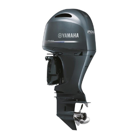
Yamaha Electone F-25 User manual

F25
T25
SERVICE MANUAL
6BP-28197-1M-11LIT-18616-03-17

Contents
General information GEN
INFO 0
Specification SPEC 1
Technical features and description TECH
FEA 2
Rigging information RIG
GING 3
Troubleshooting TRBL
SHTG 4
Electrical system ELEC 5
Fuel system FUEL 6
Power unit POWR 7
Lower unit LOWR 8
Bracket unit BRKT 9
Maintenance MNT 10
Index
Appendix A

GEN
INFO
0
General information
Safety while working ............................................................ 0-1
Rotating part............................................................................... 0-1
Hot part....................................................................................... 0-1
Electric shock ............................................................................. 0-1
Propeller ..................................................................................... 0-1
Handling of gasoline................................................................... 0-1
Ventilation................................................................................... 0-1
Self-protection ............................................................................ 0-2
Working with crane..................................................................... 0-2
Handling of gas torch ................................................................. 0-2
Part, lubricant, and sealant......................................................... 0-2
Handling of sealant..................................................................... 0-2
Special service tool .................................................................... 0-3
Tightening torque ....................................................................... 0-3
Non-reusable part....................................................................... 0-3
Disassembly and assembly........................................................ 0-3
How to use this manual ............................................................ 0-4
Manual format ............................................................................ 0-4
Abbreviation ............................................................................... 0-5
Lubricant, sealant, and thread locking agent..................... 0-6
Symbol ....................................................................................... 0-6
Special service tool.................................................................... 0-7

0-1
GEN
INFO General information
Safety while working
To prevent an accident or injury and to pro-
vide quality service, observe the following
safety procedures.
Rotating part
•Hands, feet, hair, jewelry, clothing, per-
sonal flotation device straps, and so on,
can become entangled with internal rotating
parts of the engine, resulting in serious
injury or death.
•Keep the top cowling installed whenever
possible. Do not remove or install the top
cowling when the engine is running.
•Only operate the engine with the top cowl-
ing removed according to the specific
instructions in the manual. Keep hands,
feet, hair, jewelry, clothing, personal flota-
tion device straps, and so on, away from
any exposed moving parts.
Hot part
During and after operation, engine parts are
hot enough to cause burns. Do not touch any
parts under the top cowling until the engine
has cooled.
Electric shock
Do not touch any electrical parts while start-
ing or operating the engine. Otherwise, shock
or electrocution could result.
Propeller
Do not hold the propeller with your hands
when loosening or tightening the propeller
nut.
Handling of gasoline
•Gasoline is highly flammable. Keep gaso-
line and all flammable products away from
heat, sparks, and open flames.
•Gasoline is poisonous and can cause injury
or death. Handle gasoline with care. Never
siphon gasoline by mouth. If you swallow
some gasoline, inhale a lot of gasoline
vapor, or get some gasoline in your eyes,
see your doctor immediately. If gasoline
spills on your skin, wash with soap and
water. If gasoline spills on your clothing,
change your clothes.
Ventilation
•Gasoline vapor and exhaust gas are
heavier than air and extremely poisonous.
If gasoline vapor or exhaust gas is inhaled
in large quantities, it may cause loss of con-
sciousness and death within a short time.
•When test running an engine indoors (for
example, in a water tank) make sure to do
so where adequate ventilation can be main-
tained.

0-2
0
Self-protection
•Protect your eyes by wearing safety
glasses or safety goggles during all opera-
tions involving drilling and grinding, or when
using an air compressor.
•Protect your hands and feet by wearing
protective gloves and safety shoes when
necessary.
Working with crane
•Outboard motors weighing 18.0 kg (39.7 lb)
and over must be carried by a crane.
•Use the wire ropes of adequate strength,
and lift up the outboard motor using the
three point suspension.
•If the outboard motor does not have three
or more points to be suspended, support it
using additional ropes or the like so that the
outboard motor can be lifted and carried in
a stable manner.
Handling of gas torch
•Improper handling of a gas torch may result
in burns. For information on the proper han-
dling of the gas torch, see the operation
manual issued by the manufacturer.
•When using a gas torch, keep it away from
the gasoline and oil, to prevent a fire.
•Components become hot enough to cause
burns. Do not touch any hot components
directly.
Part, lubricant, and sealant
Use only genuine Yamaha parts, lubricants,
and sealants, or those recommended by
Yamaha, when servicing or repairing the out-
board motor.
Handling of sealant
•Wear protective gloves to protect your skin,
when using the sealants.
•See the material safety data sheet issued
by the manufacturer. Some of the sealants
may be harmful to human health.
Safety while working

0-3
GEN
INFO General information
Special service tool
Use the recommended special service tools
to work safely, and to protect parts from dam-
age.
Tightening torque
Follow the tightening torque specifications
provided throughout the manual. When tight-
ening nuts, bolts, and screws, tighten the
large sizes first, and tighten fasteners starting
in the center and moving outward.
Non-reusable part
Always use new gaskets, seals, O-rings, cot-
ter pins, and so on, when installing or assem-
bling parts.
Disassembly and assembly
•Use compressed air to remove dust and dirt
during disassembly.
•Apply engine oil to the contact surfaces of
moving parts before assembly.
•Install bearings so that the bearing identifi-
cation mark is facing in the direction indi-
cated in the installation procedure. In
addition, make sure to lubricate the bear-
ings liberally.
•Apply a thin coat of water resistant grease
to the lip and periphery of an oil seal before
installation.
•Check that moving parts operate normally
after assembly.

0-5
GEN
INFO General information
Abbreviation
The following abbreviations are used in this service manual.
Abbreviation Description
ABYC American Boat and Yacht Council
API American Petroleum Institute
ATDC After Top Dead Center
BTDC Before Top Dead Center
CARB California Air Resources Board
CCA Cold Cranking Ampere
CDI Capacitor Discharge Ignition
C/L Centerline
EX Exhaust
EPA Environmental Protection Agency
FForward
IN Intake
LED Light-Emitting Diode
MCA Marine Cranking Ampere
N Neutral
PON Pump Octane Number = (RON + Motor Octane Number) /2
PORT Port side
PTT Power Trim and Tilt
R Reverse
RC Reserve Capacity
SAE Society of Automotive Engineers
SOHC Single Overhead Camshaft
STBD Starboard side
TDC Top Dead Center

0-6
0
Lubricant, sealant, and thread locking agent
Symbol
Symbols in an exploded diagram or illustration indicate the grade of lubricant and the lubrication
points.
Symbols in an exploded diagram or illustration indicate the type of sealant or thread locking agent
and the application points.
Symbol Name Application
Yamaha 4-stroke motor oil Lubricant
Gear oil Lubricant
Water resistant grease
(Yamaha grease A)
Lubricant
Molybdenum disulfide grease Lubricant
Corrosion resistant grease
(Yamaha grease D)
Lubricant
Low temperature resistant grease
(Yamaha grease C)
Lubricant
ThreeBond 1901 Lubricant
Symbol Name Application
LOCTITE 518 Sealant
ThreeBond 1322 Sealant
ThreeBond 1377B Sealant
ThreeBond 1401 Thread locking agent
LOCTITE 271 (red) Thread locking agent
1901
How to use this manual / Lubricant, sealant, and thread locking agent

0-7
GEN
INFO General information
Special service tool
For U.S.A. and Canada
Special service tools with part numbers “YB-*****” are distributed by K & L.
Special service tools with Yamaha part numbers (90890-*****) are distributed by the Parts Division.
Drilling plate
90890-06783
Digital multimeter
YU-34899-A
Peak volt adapter
YU-39991
Spark checker
YM-34487
Test harness (2 pins)
YB-06867
Test harness (2 pins)
YB-06887
LOCTITE 242 (blue) Thread locking agent
LOCTITE 572 (white) Sealant
Silicone sealant Sealant
Symbol Name Application

0-8
0
Pressure/vacuum tester
YB-35956-A
Compression gauge
YU-33223
Flywheel magnet holder
YB-06139
Universal puller
YB-06117
Crankshaft holder
YW-06355
Valve spring compressor
YM-04019
Valve attachment
YB-06320
Valve guide remover
YB-06801
Valve guide reamer
YM-01196
Valve lapping tool
YM-A8998
Lubricant, sealant, and thread locking agent / Special service tool

0-9
GEN
INFO General information
Neway valve seat kit
YB-91044
Driver handle (large)
YB-06071
Driveshaft outer race installer
YB-06110
Piston ring compressor
YM-08037
Slide hammer
YB-06096
Propeller shaft needle bearing attachment
YB-06153
Driver handle (small)
YB-06229
Bearing housing/driveshaft bearing
remover/installer
YB-06082
Driveshaft needle bearing installer and
remover
YB-06196
Bearing inner race attachment
90890-06640

0-10
0
Forward gear outer race installer
YB-06085
Driveshaft holder
YB-06079
Pinion nut wrench
YB-06078
Oil seal installer
YB-06168
Bearing splitter plate
YB-06219
Oil seal installer
YB-06023
Bearing cup installer
YB-06167
Bearing inner race attachment
90890-06644
Bearing inner race attachment
90890-06645
Pinion shim selecting tool
YB-34432-10, YB-34432-11A, YB-34432-16,
YB-34432-17
Special service tool

0-11
GEN
INFO General information
Forward gear shim gauge
YB-06344
Reverse gear shim gauge
YB-39799
Bearing housing puller
YB-06234
Backlash indicator rod
YB-06265
Dial indicator gauge
YU-03097
Backlash adjustment plate
YB-07003
Magnetic base stand
YU-A8438
Pinion height gauge
90890-06668
Bearing puller legs
YB-06523
Bearing housing bearing/oil seal remover
YB-06112

0-12
0
Bearing housing bearing/oil seal installer
YB-06111
Driveshaft holder
YB-06079
Roller bearing installer/remover
YB-06432
Driveshaft needle bearing
remover/installer
YB-06063
Forward gear outer race installer
YB-41446
Driveshaft outer race installer
YB-06110
Forward gear bearing installer
YB-06270-A
Bearing installer-reverse gear bearing
YB-06016
Bearing housing puller
YB-06207
Reverse gear bearing remover
YB-41707
Special service tool

0-13
GEN
INFO General information
Pinion gear bushing installer
YB-06029-4
Crankshaft seal installer
YB-06349
Driveshaft needle bearing installer and
remover
YB-06230
Trim/cylinder wrench
YB-06175-2B
Digital tachometer
YU-39951-B

SPEC
Specification
Model features............................................................................. 1-1
General feature .......................................................................... 1-1
Model designation ...................................................................... 1-2
Serial number ............................................................................. 1-2
Model data .................................................................................... 1-3
Dimension and Weight ............................................................... 1-3
Performance............................................................................... 1-3
Power unit .................................................................................. 1-4
Bracket unit ................................................................................ 1-5
Lower unit................................................................................... 1-5
Fuel and oil requirement............................................................. 1-6
Battery requirement.................................................................... 1-7
PTT requirement ........................................................................ 1-7
Electrical technical data ........................................................... 1-7
Ignition timing control system ..................................................... 1-7
Engine speed control system ..................................................... 1-9
PTT system .............................................................................. 1-10
Charging system ...................................................................... 1-10
Starting system......................................................................... 1-11
Fuel system technical data.................................................... 1-12
Fuel system .............................................................................. 1-12
Power unit technical data....................................................... 1-13
Power unit ................................................................................ 1-13
Manual starter .......................................................................... 1-14
Cylinder head assembly ........................................................... 1-14
Crankcase assembly ................................................................ 1-17
Lower unit technical data....................................................... 1-19
Lower unit assembly................................................................. 1-19
Bracket unit technical data.................................................... 1-20
PTT system .............................................................................. 1-20

1
Special tightening torque....................................................... 1-20
Rigging information .................................................................. 1-20
Fuel system .............................................................................. 1-20
Power unit ................................................................................ 1-21
Lower unit................................................................................. 1-22
Bracket unit .............................................................................. 1-22
PTT unit.................................................................................... 1-23
Optional equipment .................................................................. 1-23
General tightening torque...................................................... 1-23

1-1
SPEC Specification
Model features
General feature
F25 and T25 Overall Features
•Single carburetor with accelerator pump
•4-stroke, L2, SOHC, 4-valve, 498.0 cm3(30.4 cu. in) engine
•Low emission in compliance with US EPA and US CARB 3-STAR emission standards
aPower unit
•Counter balancer
•Decompression easy starter
(Manual starter model)
•Long tubed intake manifold
•Blowby gas reburning system
bElectrical
•Prime Start
•Protection system for over-revving
•Alert systems for low oil pressure and over-
heating
cBracket unit
•Long span mounts (F25)
•Large mounts (T25)
•Small and compact PTT (PTT model)
•Single operation steering friction (Tiller han-
dle model)
•Multifunction tiller handle (Optional)
dUpper case
•Labyrinth idle exhaust system
eLower unit
•Waist drive shaft
•Lower unit from outboard motor in next
higher class (T25)
•2.42 high gear ratio (T25)
•Dual thrust propeller (T25)
c
e
b
a
d

1-2
1
Model designation
Serial number
The outboard motor serial number is indi-
cated on a label affixed to the port clamp
bracket.
1Model name
2Approved model code
3Transom height
4Serial number
5Production model year (G: 2009)
1Model description F: 4-stroke regular rotation
T: 4-stroke regular rotation (high thrust)
2Model name 25: 25
3Transom height S: S (15 in)
L: L (20 in)
4
Functions
M: Manual starter
E: Electric starter
Blank: PTT and electric starter
5H: Tiller handle
Blank: Remote control
6Product generation A: A and up
F 25 L E H A
1 2 3 4 5 6
Model name Approved
model code
Starting
serial No.
F25MHA 6BP 1000001–
F25EHA 6BP 1000001–
F25EA 6BP 1000001–
F25A 6BP 1000001–
T25A 6BL 1000001–
YAMAHA MOTOR CO., LTD.
MADE IN JAPAN
PAYS D'ORIGINE JAPON
2
31
4
5
Model features
Other manuals for Electone F-25
8
This manual suits for next models
6
Table of contents
Other Yamaha Outboard Motor manuals
Popular Outboard Motor manuals by other brands

Outboards Group
Outboards Group FPP2.8A owner's manual

Sleipner
Sleipner SEP-IP50 installation guide

Panther
Panther Freshwater 55-0102 Installation and operating instructions

Sleipner
Sleipner SEP20 installation manual

TOHATSU
TOHATSU BFT 200D owner's manual

Mitek
Mitek MO Series Operation and maintenance manual