Yamaha F25A User manual

F2.5A
SERVICE MANUAL
69M-28197-3E-11
290470

NOTICE
This manual has been prepared by Yamaha primarily for use by Yamaha dealers and their trained
mechanics when performing maintenance procedures and repairs to Yamaha equipment. It has
been written to suit the needs of persons who have a basic understanding of the mechanical and
electrical concepts and procedures inherent in the work, for without such knowledge attempted
repairs or service to the equipment could render it unsafe or unfit for use.
Because Yamaha has a policy of continuously improving its products, models may differ in detail
from the descriptions and illustrations given in this publication. Use only the latest edition of this
manual. Authorized Yamaha dealers are notified periodically of modifications and significant
changes in specifications and procedures, and these are incorporated in successive editions of this
manual.
Important information 1
Particularly important information is distinguished in this manual by the following notations:
The Safety Alert Symbol means ATTENTION! BECOME ALERT! YOUR SAFETY IS
INVOLVED!
WARNING
Failure to follow WARNING instructions could result in severe injury or death to the machine
operator, a bystander, or a person inspecting or repairing the outboard motor.
CAUTION:
A CAUTION indicates special precautions that must be taken to avoid damage to the out-
board motor.
NOTE:
A NOTE provides key information to make procedures easier or clearer.
F2.5A
SERVICE MANUAL
©2002 by Yamaha Motor Co., Ltd.
1st Edition, May 2002
All rights reserved.
Any reprinting or unauthorized use
without the written permission of
Yamaha Motor Co., Ltd.
is expressly prohibited.
Printed in the Netherlands

Contents
General information 1
GEN
INFO
Specifications 2
SPEC
Periodic checks and adjustments 3
CHK
ADJ
Fuel system 4
FUEL
Power unit 5
POWR
Lower unit 6
LOWR
Bracket unit 7
BRKT
Electrical systems 8
ELEC
Troubleshooting 9
TRBL
SHTG
Index
–+


69M3E11
GEN
INFO
1
2
3
4
5
6
7
8
9
General information
How to use this manual.................................................................................1-1
Manual format............................................................................................1-1
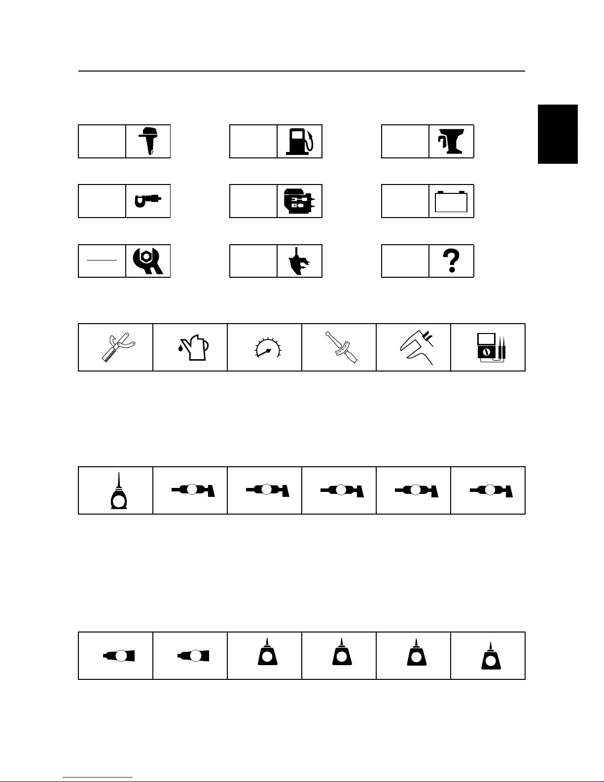
Symbols.....................................................................................................1-2
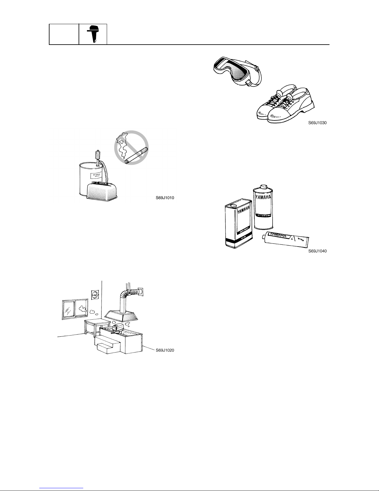
Safety while working......................................................................................1-3
Fire prevention...........................................................................................1-3
Ventilation..................................................................................................1-3
Self-protection ...........................................................................................1-3
Parts, lubricants, and sealants ..................................................................1-3
Good working practices .............................................................................1-4
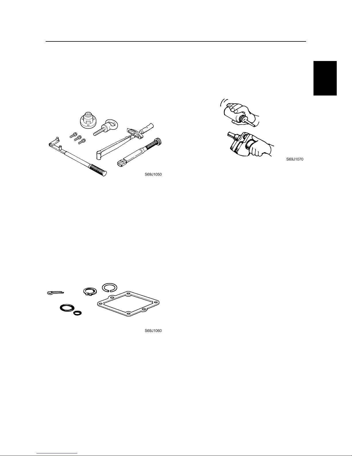
Disassembly and assembly .......................................................................1-4
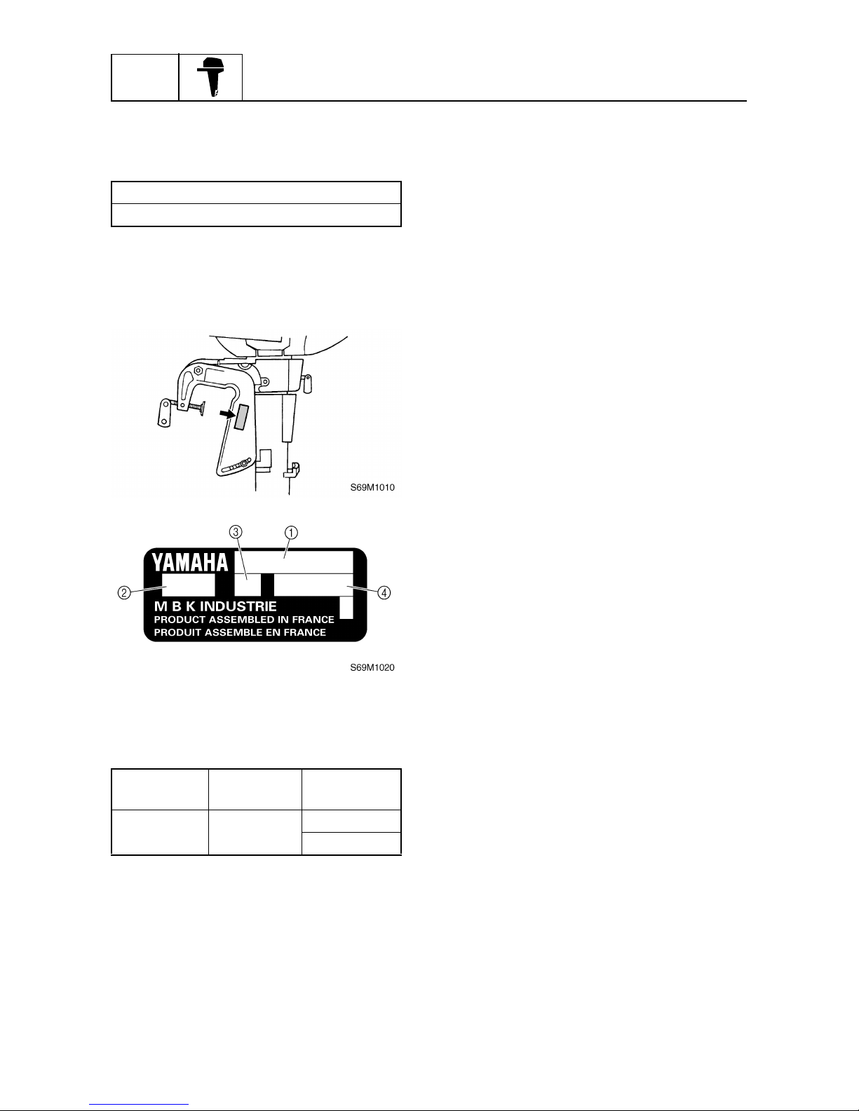
Identification...................................................................................................1-5
Applicable model .......................................................................................1-5
Serial number ............................................................................................1-5
Features and benefits....................................................................................1-6
Ignition system...........................................................................................1-6
Blowby gas reburning system....................................................................1-7
Oil check window.......................................................................................1-8
Idle silencer ...............................................................................................1-9
Splash lubrication system........................................................................1-10
Low vibration tiller handle ........................................................................1-11
Technical tips ...............................................................................................1-12
TCI system ..............................................................................................1-12
Automatic tilt support and steering pivot immobilization system .............1-13
Cooling water flow chart ..........................................................................1-14
Propeller selection.......................................................................................1-15
Propeller size...........................................................................................1-15
Selection..................................................................................................1-15
Predelivery checks ......................................................................................1-15
Checking the fuel system ........................................................................1-15
Checking the gear oil...............................................................................1-15
Checking the engine oil ...........................................................................1-16
Checking the outboard motor mounting height........................................1-16
Checking the steering system .................................................................1-16
Checking the gear shift and throttle operation.........................................1-17
Checking the engine shut-off switch........................................................1-17
Checking the cooling water pilot hole ......................................................1-17
Test run ...................................................................................................1-18
Break-in ...................................................................................................1-18
After test run ............................................................................................1-18
Adjusting the engine idle speed...............................................................1-18

GEN
INFO General information
1-1 69M3E11
How to use this manual 1
Manual format
The format of this manual has been designed to make service procedures clear and easy to under-
stand. Use the information below as a guide for effective and quality service.
1Parts are shown and detailed in an exploded diagram and are listed in the components list.
2Tightening torque specifications are provided in the exploded diagrams and after a numbered
step with tightening instructions.
3Symbols are used to indicate important aspects of a procedure, such as the grade of lubricant
and lubrication point.
4The components list consist of part names and part quantities, as well as bolt and screw dimen-
sions.
5Service points regarding removal, checking, and installation are shown in individual illustrations
to explain the relevant procedure.
NOTE:
For troubleshooting procedures, see Chapter 9, “Troubleshooting.”
LOWR Lower unit
6-5 62Y5A11
Lower unit
No. Part name Q’ty Remarks
1 Lower unit 1
2 Plastic tie 1 Not reusable
3Hose 1
4 Check screw 1
5 Gasket 2 Not reusable
6 Dowel pin 2
7 Bolt 4 M10 40 mm
8 Drain screw 1
9Grommet 1
10 Bolt 1 M10 45 mm
11 Bolt 1 M8 60 mm
12 Thrust washer 1
13 Propeller 1
14 Washer 1
15 Washer 1
16 Cotter pin 1 Not reusable
17 Propeller nut 1
18 Trim tab 1
LOWR Lower unit
6-19 62Y5A11
Removing the drive shaft
1. Remove the drive shaft assembly and
pinion, and then pull out the forward
gear.
Disassembling the drive shaft
1. Install the pinion nut 1, tighten it finger
tight, and then remove the drive shaft
bearing 2using a press.
CAUTION:
• Do not press the drive shaft threads a
directly.
• Do not reuse the bearing, always
replace it with a new one.
Disassembling the forward gear
1. Remove the taper roller bearing from the
forward gear using a press.
CAUTION:
Do not reuse the bearing, always replace
it with a new one.
2. Remove the needle bearing from the for-
ward gear.
CAUTION:
Do not reuse the bearing, always replace
it with a new one.
Drive shaft holder 4 1: 90890-06518
Pinion nut holder 2: 90890-06505
Socket adapter 2 3: 90890-06507
Bearing inner race attachment 3:
90890-06639
S62Y6850K
Bearing separator 1: 90890-06534
Stopper guide plate 2: 90890-06501
Stopper guide stand 3:
90890-06538
Bearing puller 4: 90890-06535
Bearing puller claw 1 5:
90890-06536
S62Y6740K
5
4
321

69M3E11 1-2
1
2
3
4
5
6
7
8
9
Symbols
The symbols below are designed to indicate the content of a chapter.
General information
Specifications
Periodic checks and adjustments
Fuel system
Power unit
Lower unit
Bracket unit
Electrical systems
Troubleshooting
GEN
INFO
SPEC
CHK
ADJ
FUEL
POWR
LOWR
BRKT
ELEC
TRBL
SHTG
–+
Symbols 1to 6indicate specific data.
1Special tool
2Specified oil or fluid
3Specified engine speed
4Specified tightening torque
5Specified measurement
6Specified electrical value
(resistance, voltage, electric current)
Symbols 7to Bin an exploded diagram indicate the grade of lubricant and the lubrication point.
7Apply Yamaha 4-stroke motor oil
8Apply water resistant grease (Yamaha grease A)
9Apply molybdenum disulfide grease
0Apply corrosion resistant grease
(Yamaha grease D)
AApply low temperature resistant grease
(Yamaha grease C)
BApply injector grease
Symbols Cto Hin an exploded diagram indicate the type of sealant or locking agent and the appli-
cation point.
CApply Gasket Maker
DApply Yamabond No. 4
EApply LOCTITE 271 (red)
FApply LOCTITE 242 (blue)
GApply LOCTITE 572
HApply silicon sealant
123456
T
R
.
.
7890AB
E
A M
D
CI
CDEFGH
GM
4
271
LT
242
LT
572
LT SS
How to use this manual

GEN
INFO General information
1-3 69M3E11
Safety while working 1
To prevent an accident or injury and to
ensure quality service, follow the safety pro-
cedures provided below.
Fire prevention
Gasoline is highly flammable.
Keep gasoline and all flammable products
away from heat, sparks, and open flames.
Ventilation
Gasoline vapor and exhaust gas are heavier
than air and extremely poisonous. If inhaled
in large quantities they may cause loss of
consciousness and death within a short time.
When test running an engine indoors (e.g., in
a water tank) be sure to do so where ade-
quate ventilation can be maintained.
Self-protection
Protect your eyes by wearing safety glasses
or safety goggles during all operations involv-
ing drilling and grinding, or when using an air
compressor.
Protect your hands and feet by wearing pro-
tective gloves and safety shoes when neces-
sary.
Parts, lubricants, and sealants
Use only genuine Yamaha parts, lubricants,
and sealants or those recommended by
Yamaha, when servicing or repairing the out-
board motor.
Under normal conditions, the lubricants men-
tioned in this manual should not harm or be
hazardous to your skin. However, you should
follow these precautions to minimize any risk
when working with lubricants.
1. Maintain good standards of personal and
industrial hygiene.
2. Change and wash clothing as soon as
possible if soiled with lubricants.
3. Avoid contact with skin. Do not, for
example, place a soiled rag in your
pocket.
4. Wash hands and any other part of the
body thoroughly with soap and hot water
after contact with a lubricant or lubricant
soiled clothing has been made.
5. To protect your skin, apply a protective
cream to your hands before working on
the outboard motor.

69M3E11 1-4
1
2
3
4
5
6
7
8
9
6. Keep a supply of clean, lint-free cloths for
wiping up spills, etc.
Good working practices
Special service tools
Use the recommended special service tools
to protect parts from damage. Use the right
tool in the right manner—do not improvise.
Tightening torques
Follow the tightening torque specifications
provided throughout the manual. When tight-
ening nuts, bolts, and screws, tighten the
large sizes first, and tighten fasteners starting
in the center and moving outward.
Non-reusable parts
Always use new gaskets, seals, O-rings, cot-
ter pins, circlips, etc., when installing or
assembling parts.
Disassembly and assembly
1. Use compressed air to remove dust and
dirt during disassembly.
2. Apply engine oil to the contact surfaces
of moving parts before assembly.
3. Install bearings with the manufacture
identification mark in the direction indi-
cated in the installation procedure. In
addition, be sure to lubricate the bearings
liberally.
4. Apply a thin coat of water-resistant
grease to the lip and periphery of an oil
seal before installation.
5. Check that moving parts operate nor-
mally after assembly.
Safety while working

GEN
INFO General information
1-5 69M3E11
Identification 1
Applicable model
This manual covers the following model.
Serial number
The outboard motor serial number is
stamped on a label attached to the port
clamp bracket.
1Model name
2Approved model code
3Transom height
4Serial number
Applicable model
F2.5AMH
Model name Approved
model code
Starting
serial No.
F2.5AMH 69M S: 1000101–
L: 1000101–

69M3E11 1-6
1
2
3
4
5
6
7
8
9
Features and benefits 1
Ignition system
A simple and compact ignition system is adopted. In this ignition system, high voltage is induced in
the secondary coil when the electric current produced by the primary coil and the permanent mag-
net on the rotating flywheel is cut off.
This TCI (Transistor Controlled Ignition) system greatly contributes to a compact and lightweight
engine.
1TCI unit
2Permanent magnet
3Flywheel
aAir gap: 0.4–0.6 mm (0.016–0.024 in)
1Flywheel
2Permanent magnet
3Core
4Primary coil
5Secondary coil
6Spark plug
7Transistor 1
8Transistor 2
9Engine shut-off switch
S69M1130
123
4
5
6
7
8
9
Identification / Features and benefits

GEN
INFO General information
1-7 69M3E11
Blowby gas reburning system
The splash lubrication system splashes a large quantity of oil into the blowby gases. Therefore, a
reburning system is incorporated to separate the oil from the blowby gases in two stages: first in the
cylinder head and second in the intake silencer.
Oil is first separated from the blowby gases in the cylinder head labyrinth. The oil flows into the cyl-
inder head and the gases are discharged into the intake silencer.
Blowby gases from the cylinder head flow into the intake silencer and oil is then separated from the
gases in the intake silencer labyrinth. The oil flows from the bottom of the intake silencer into the oil
pan through the blowby hose and the gases are drawn into the carburetor and reburned in the
engine.
1To intake silencer
2From cylinder head
3To oil pan
ÈBlowby gas
ÉEngine oil
ÊCylinder head
ËIntake silencer
S69M1140
Ê
Ë
:È
:É
3
2
1

69M3E11 1-8
1
2
3
4
5
6
7
8
9
Oil check window
The F2.5 is equipped with an oil check window to make engine oil level checks easier.
The oil checking plate in the oil check window indicates the proper oil level when the outboard motor
is in an upright position.
The end of the oil checking plate indicates the minimum level. The oil level should be between the
maximum and minimum levels.
1Oil checking plate
aMaximum level
bMinimum level
S69M1150
1
a
b
Features and benefits

GEN
INFO General information
1-9 69M3E11
Idle silencer
The idle silencer is installed to the upper case to reduce exhaust noise and carbon deposits around
the exhaust idle port.
Exhaust gases are discharged into the idle silencer from the two upper holes in the upper case. The
gases flow and eddy (swirl) inside the silencer and then are discharged from the exhaust idle port of
the silencer into the atmosphere.
The cooling water in the silencer flows into lower hole in the upper case.
ÈExhaust gas
ÉCooling water
S69M1160
:È
:É

69M3E11 1-10
1
2
3
4
5
6
7
8
9
Splash lubrication system
A simple splash lubrication system design is adopted.
The splasher is driven by the oil splasher gear installed on the camshaft and splashes oil in the oil
pan onto the internal parts of the crankcase.
S69M1170
Features and benefits

GEN
INFO General information
1-11 69M3E11
Low vibration tiller handle
The tiller handle is installed near the center of the outboard motor for low vibration.
To help reduce vibration transferring to the tiller handle, a rubber damper is used at the installation
point of the handle.
The tiller handle is equipped with a throttle indicator to indicate the throttle angle, an engine shut-off
switch to turn the engine off in an emergency, and a throttle friction adjuster to adjust the friction of
the throttle lever.
1Rubber damper
2Throttle grip
3Throttle indicator
4Engine shut-off switch
5Throttle friction adjuster
S69M1190
2
3
5
4
1

69M3E11 1-12
1
2
3
4
5
6
7
8
9
Technical tips 1
TCI system
The TCI system operates as follows.
Before ignition
As the flywheel rotates, the primary coil generates a voltage and an electric current A. This electric
current opens transistor Q1 and, as a result, an electric current Bflows to the primary coil.
Ignition
As the flywheel continues to rotate, the voltage generated by the primary coil increases.
When the voltage reaches the operation voltage of transistor Q2, an electric current Cflows to tran-
sistor Q2 and opens it. As a result, electric current Dflows.
Ignition timing occurs in this instant.
At ignition timing, the electric current Bflowing to the primary coil through transistor Q1 is cut off,
the secondary coil generates a high voltage by electric induction and an ignition spark is fired by the
spark plug.
S69M1200
AB
Q1
Q2
S69M1210
C
D
Q2
B
Q1
Features and benefits / Technical tips

GEN
INFO General information
1-13 69M3E11
Automatic tilt support and steering pivot immobilization system
The tilt support lever is constantly pushed against the clamp bracket by the force of a spring.
When the outboard motor is fully tilted up in the forward steering position, the stopper linked to the
tilt support lever is inserted into the swivel cutout. At the same time, the tilt support lever automati-
cally supports the outboard motor on the clamp bracket.
If the outboard motor is tilted up with the steering in either direction, the stopper is not inserted into
the swivel cutout and the tilt support lever linked to the stopper does not support the outboard
motor.
The stopper, which is fitted on the swivel, prevents the outboard motor from swiveling when fully
tilted up in the forward steering position.
1Spring
2Tilt support lever
3Stopper
4Swivel recess
S69M1220
2
1
34

69M3E11 1-14
1
2
3
4
5
6
7
8
9
Cooling water flow chart
ÈCold water
ÉHot water
ÊExhaust gas and water
S69M1230
Upper case
(Top starboard
side)
Upper case
(Inside)
Crankcase
Cooling water
pilot hole
Atmosphere Water pump Lower case
exhaust port
Cooling water
inlet Atmosphere
Cylinder
block
Cylinder
head
Thermostat
:È
:É
:Ê
Technical tips

GEN
INFO General information
1-15 69M3E11
Propeller selection 1
The performance of a boat and outboard
motor will be critically affected by the size
and type of propeller you choose. Propellers
greatly affect boat speed, acceleration,
engine life, fuel economy, and even boating
and steering capabilities. An incorrect choice
could adversely affect performance and
could also seriously damage the engine.
Use the following information as a guide for
selecting a propeller that meets the operating
conditions of the boat and the outboard
motor.
Propeller size
The size of the propeller is indicated on the
propeller blade.
aPropeller diameter (in inches)
bPropeller pitch (in inches)
cPropeller type (propeller mark)
Selection
When the engine speed is at the full throttle
operating range (5,250–5,750 r/min), the
ideal propeller for the boat is one that pro-
vides maximum performance in relation to
boat speed and fuel consumption.
Predelivery checks 1
To make the delivery process smooth and
efficient, the predelivery checks should be
completed as explained below.
Checking the fuel system
1. Check that the fuel hose is securely con-
nected and that the fuel tank is full with
fuel.
CAUTION:
This is a 4-stroke engine. Never use pre-
mixed fuel.
Checking the gear oil
1. Check the gear oil level.
Propeller size (in) Material
7 1/4 ×6 - BS
Aluminum
7 1/4 ×5 1/2 - BS
7 1/4 ×7 1/4 - BS
7 1/4 ×8 1/4 - BS
7 1/2 ×5 1/2 - BS
S69J1110
× -
abc
S69M1040
Other manuals for F25A
5
Table of contents
Other Yamaha Outboard Motor manuals
Popular Outboard Motor manuals by other brands

Craftsman
Craftsman Gamefisher 298.585070 owner's manual

TOHATSU
TOHATSU MFS 9.9E Series owner's manual

Mercury
Mercury 4.5 Operation and maintenance manual

Quick
Quick BTAC Series Installation and user manual

SELVA MARINE
SELVA MARINE Grey Whale 200 EFI Service manual

Outboards Group
Outboards Group F50A owner's manual