Yamaha F60A Manual

SERVICE MANUAL
292098 69W-28197-3D-1X
SUPPLEMENTARY
F60A

NOTICE
This Supplementary Service Manual has been prepared to introduce new service and new data
information for the F60 which is based on the F50. For complete information on service procedures,
it is necessary to use this Supplementary Service Manual together with the following manual.
Important information 1
Particularly important information is distinguished in this manual by the following notations:
The Safety Alert Symbol means ATTENTION! BECOME ALERT! YOUR SAFETY IS
INVOLVED!
WARNING
Failure to follow WARNING instructions could result in severe injury or death to the machine
operator, a bystander, or a person inspecting or repairing the outboard motor.
CAUTION:
A CAUTION indicates special precautions that must be taken to avoid damage to the out-
board motor.
NOTE:
A NOTE provides key information to make procedures easier or clearer.
F50A, FT50B, FT50C SERVICE MANUAL: 62Y-28197-3A-11
F60A
SUPPLEMENTARY SERVICE MANUAL
©2001 by Yamaha Motor Co., Ltd.
1st Edition, July 2001
All rights reserved.
Any reprinting or unauthorized use
without the written permission of
Yamaha Motor Co., Ltd.
is expressly prohibited.
Printed in the Netherlands

Contents
General information 1
GEN
INFO
Specifications 2
SPEC
Periodic checks and adjustments 3
CHK
ADJ
Fuel system 4
FUEL
Power unit 5
POWR
Lower unit 6
LOWR
Bracket unit 7
BRKT
Electrical systems 8
ELEC
Troubleshooting 9
TRBL
SHTG
Index
–+

69W3D1X
General information
How to use this manual.................................................................................... 1
Manual format............................................................................................... 1
Symbols........................................................................................................ 2
Identification...................................................................................................... 3
Applicable models ........................................................................................ 3
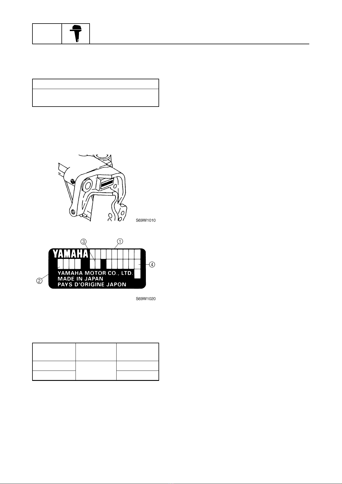
Serial number ............................................................................................... 3
Features and benefits....................................................................................... 4
Power unit..................................................................................................... 4
Carburetors................................................................................................... 5
Lower unit ..................................................................................................... 7
Bracket unit................................................................................................... 9
Electrical unit .............................................................................................. 10
Technical tips .................................................................................................. 11
Carburetor .................................................................................................. 11
PTT (Power Trim and Tilt) unit ................................................................... 12
Propeller selection.......................................................................................... 13
Propeller size.............................................................................................. 13
Selection..................................................................................................... 13
Predelivery checks ......................................................................................... 14
Checking the fuel system ........................................................................... 14
Checking the gear oil.................................................................................. 14
Checking the engine oil .............................................................................. 14
Checking the battery................................................................................... 14
Checking the outboard motor mounting height........................................... 14
Checking the shift/throttle cables................................................................ 15
Checking the steering system .................................................................... 15
Checking the gearshift and throttle operation............................................. 16
Checking the tilt system.............................................................................. 16
Checking the engine start switch and engine stop switch/
engine shut-off switch ............................................................................... 16
Checking the cooling water pilot hole ......................................................... 17
Test run ...................................................................................................... 17
Break-in ...................................................................................................... 17
After test run ............................................................................................... 17

69W3D1X
Specifications
General specifications.................................................................................... 18
Maintenance specifications ........................................................................... 20
Power unit................................................................................................... 20
Lower unit ................................................................................................... 24
Electrical ..................................................................................................... 24
Dimensions................................................................................................. 27
Tightening torques.......................................................................................... 32
Specified torques........................................................................................ 32
General torques.......................................................................................... 33
Periodic checks and adjustments
Special service tools ...................................................................................... 34
Maintenance interval chart............................................................................. 36
Top cowling ..................................................................................................... 37
Checking the top cowling............................................................................ 37
Fuel system ..................................................................................................... 37
Checking the fuel filter ................................................................................ 37
Power unit........................................................................................................ 37
Checking the thermostat............................................................................. 37
General............................................................................................................. 38
Checking the anodes.................................................................................. 38
Lubrication .................................................................................................. 39
Fuel system
Hose routing .................................................................................................... 40
Fuel and blowby hoses............................................................................... 40
Cooling water hose..................................................................................... 41
Fuel line and fuel filter.................................................................................... 42
Carburetor unit ................................................................................................ 43
Adjusting the dashpot (acceleration pump) ................................................ 44

69W3D1X
Power unit
Power unit........................................................................................................ 45
Checking the compression pressure .......................................................... 55
Checking the oil pressure ........................................................................... 55
Checking the cylinder bore ......................................................................... 56
Checking the piston ring grooves ............................................................... 56
Lower unit
Drive shaft and lower case............................................................................. 57
Removing the drive shaft............................................................................ 59
Disassembling the forward gear ................................................................. 59
Assembling the forward gear...................................................................... 59
Installing the drive shaft.............................................................................. 59
Shimming......................................................................................................... 60
Shimming.................................................................................................... 61
Selecting the forward gear shims ............................................................... 61
Bracket unit
Tiller handle ..................................................................................................... 63
Bottom cowling ............................................................................................... 65
Upper case....................................................................................................... 67
Disassembling the oil pan........................................................................... 71
Assembling the oil pan ............................................................................... 71
Installing the upper case............................................................................. 72
Clamp brackets ............................................................................................... 74
Adjusting the trim sensor ............................................................................ 75
Swivel bracket and steering arm ................................................................... 76
Power trim and tilt unit ................................................................................... 77
Disassembling the gear pump .................................................................... 82
Checking the valves ................................................................................... 82
Assembling the gear pump......................................................................... 83
Checking the trim sensor............................................................................ 84

69W3D1X
Electrical systems
Wiring harness ................................................................................................ 85
Ignition and ignition control system ............................................................. 86
Checking the spark plug caps .................................................................... 88
Checking the pulser coil air gap ................................................................. 88
Checking the engine start switch................................................................ 88
Starting system ............................................................................................... 89
Starter motor ................................................................................................... 90
Checking the armature ............................................................................... 91
Checking the brushes................................................................................. 91
Wiring diagram

GEN
INFO General information
169W3D1X
How to use this manual 1
Manual format
The format of this manual has been designed to make service procedures clear and easy to under-
stand. Use the information below as a guide for effective and quality service.
1Parts are shown and detailed in an exploded diagram and are listed in the components list.
2Tightening torque specifications are provided in the exploded diagrams and after a numbered
step with tightening instructions.
3Symbols are used to indicate important aspects of a procedure, such as the grade of lubricant
and lubrication point.
4The components list consist of parts and part quantities, as well as bolt, screw, O-ring, and hose
dimensions.
5Service points regarding removal, checking, and installation are shown in individual illustrations
to explain the relevant procedure.
NOTE:
For troubleshooting procedures, see Chapter 9, “Troubleshooting.”

69W3D1X 2
Symbols
The symbols below are designed to indicate the content of a chapter.
General information
Specifications
Periodic checks and adjustments
Fuel system
Power unit
Lower unit
Bracket unit
Electrical systems
Troubleshooting
GEN
INFO
SPEC
CHK
ADJ
FUEL
POWR
LOWR
BRKT
ELEC
TRBL
SHTG
–+
Symbols 1to 6indicate specific data.
1Special tool
2Specified oil or fluid
3Specified engine speed
4Specified tightening torque
5Specified measurement
6Specified electrical value
(resistance, voltage, electric current)
Symbols 7to Ain an exploded diagram indicate the grade of lubricant and the lubrication point.
7Apply Yamaha 4-stroke motor oil
8Apply water resistant grease (Yamaha grease A)
9Apply molybdenum disulfide grease
0Apply corrosion resistant grease
(Yamaha grease D)
AApply low temperature resistant grease
(Yamaha grease C)
Symbols Bto Gin an exploded diagram indicate the type of sealant or locking agent and the appli-
cation point.
BApply Gasket Maker®
CApply Yamabond No. 4
DApply LOCTITE®No. 271 (Red)
EApply LOCTITE®No. 242 (Blue)
FApply LOCTITE®No. 572
GApply silicon sealant
123456
T
R
.
.
7890A
E
A M D C
BCDEFG
GM
4
271
LT
242
LT
572
LT SS
How to use this manual
1
2
3
4
5
6
7
8
9

GEN
INFO General information
369W3D1X
Identification 1
Applicable models
This manual covers the following models.
Serial number
The outboard motor serial number is
stamped on a label attached to the port
clamp bracket.
1Model name
2Approved model code
3Transom height
4Serial number
Applicable models
F60AEHT
F60AET
Model name Approved
model code
Starting
serial No.
F60AEHT 69W L: 500101–
F60AET L: 400101–

69W3D1X 4
Features and benefits 1
Power unit
Based on the power unit of the field-proven F50, newly designed parts have been adopted in the
various areas to attain 60 horsepower. The newly designed parts include the intake valves, exhaust
valves, cylinder head, pistons, and the intake silencer.
Cylinder head
The shape of the combustion chamber has been changed to increase its capacity.
The diameter of the intake and exhaust valves have been enlarged to increase output.
1Combustion chamber
2Intake valve
3Exhaust valve
S69W1200
F50 F60
F60F50
83.5 mm
(3.29 in)
84.1 mm
(3.31 in)
84.0 mm
(3.31 in)
84.8 mm
(3.34 in)
30.0 mm (1.18 in) 26.0 mm (1.02 in) 32.0 mm (1.26 in) 26.7 mm (1.05 in)
Identification / Features and benefits

GEN
INFO General information
569W3D1X
Oil pump
The size of the oil pump rotor has been enlarged to increase the oil discharge volume. As a result,
reliable lubrication has been realized.
1Rotor
2Embossed letters for identification
Carburetors
To achieve the high power output of the F60, the carburetor bores have been enlarged.
Oil discharge volume
F50 21.5 L (5.68 US gal, 0.22 Imp gal)/min
F60 23.5 L (6.21 US gal, 5.17 Imp gal)/min
Comparison chart of carburetor bores
Throttle valve Venturi
F50 ø27 ø22
F60 ø30 ø25
S69W1210
22 mm (0.87 in) 24 mm (0.94 in)
F50 F60
S69W1220
F50 F60
Ø27
Ø22
Ø30
Ø25

69W3D1X 6
Although the main jet specification numbers of the F50 differed between cylinders, the F60 uses
main jets with the same specification number for all four cylinders due to the change in shape of the
intake silencer.
ÈAir
Power nozzle
The F60 uses a power nozzle in its carburetors. This nozzle provides a rich air-fuel mixture to
ensure the proper output when operating at high engine speeds.
1Power nozzle
2Fuel inlet
ÈAir-fuel mixture
S69W1230
F50 F60 :
Comparison chart of main jet diameters
Cylinder#1#2#3#4
F50 #124 #126 #116 #114
F60 #124 #124 #124 #124
:S69W1240
Features and benefits

GEN
INFO General information
769W3D1X
Lower unit
Drive shaft
The drive shaft has been machined to accommodate the high power output. The portion that
mounts to the pinion gear has been machined with involute splines to increase durability. A section
of the midspan of the drive shaft has been reduced to 14.4 mm (0.57 in) to prevent the drive shaft
from breaking under impact loads. In addition, two grooves are provided on the drive shaft for iden-
tification purposes.
1Grooves for identification
2Involute splines
3Angled splines
S69W1250
95.5 mm
(3.76 in)
Ø14.4
F50:
F60:

69W3D1X 8
Forward gear bearing
The size of the forward gear bearing has been increased to accommodate the high power output of
the F60. With this increase, the coupling length of the forward gear has been extended as well. In
addition, two grooves are provided on the forward gear for identification purposes.
1Forward gear bearing
2Grooves for identification
3Forward gear
Propeller
The propeller of the F60 has been newly designed (69W series). The strength of the propeller
blades and the slipping resistance of the damper have been increased. The 11-, 13-, and 15-inch
propellers of the currently used 663 series will be gradually replaced by the 69W series.
Bearing comparison chart
Forward gear bearing Forward gear
F50 22.2 mm (0.87 in) 18.5 mm (0.73 in)
F60 26.0 mm (1.02 in) 23.2 mm (0.91 in)
S69W1260
26.0 mm
(1.02 in) 23.2 mm
(0.91 in)
Features and benefits

GEN
INFO General information
969W3D1X
Bracket unit
PTT (Power trim and tilt) unit
Based on the 62Y type PTT unit of the F50, the internal valve and power trim and tilt motor have
been changed. The construction of the valves has been changed to increase the shut-off pressure.
The unit limits the movement of the outboard motor, which has increased in size with the increase in
its power output, and secures it in place.
1PTT motor
2Identification mark
3Tilt piston absorber
4Tilt and trim cylinder
5Manual valve
6Up-relief valve
7Down-relief valve
8Gear pump
ÈShut-off pressure of the F60 valves
ÉShut-off pressure of the F50 valves
Specified PTT motor output
F50A 12 V 0.15 kW
F60A 12 V 0.20 kW
69W-00
S69W1270
31 MPa [316 kgf/cm2]
(31 MPa [316 kgf/cm2])
18 MPa [184 kgf/cm2]
(14 MPa [143 kgf/cm2])
3.3 MPa [34 kgf/cm2]
(2.0 MPa [20.4 kgf/cm2])
12 MPa [122 kgf/cm2]
(10 MPa [102 kgf/cm2])

69W3D1X 10
Steering friction
The F60 tiller handle models use a newly developed, compact steering friction.
1Steering friction
Electrical unit
Starter motor
The starter motor uses six magnets and four brushes to enhance its operating torque.
1Bearing
2Starter relay
3Neutral switch
4Engine start switch
5Magnet
6Brush
7Starter motor
8Battery
S69W1280
S69W1290
F50 F60
Operating torque
F50 2.74 N·m (0.27 kgf·m, 2.0 ft·lb)
F60 3.50 N·m (0.35 kgf·m, 2.5 ft·lb)
Features and benefits

GEN
INFO General information
11 69W3D1X
Technical tips 1
Carburetor
Power nozzle
The power nozzle is activated when the engine is operating at high speeds. To reduce the fuel con-
sumption rate and the pollution of the exhaust gases, the carburetors of the F60 are set lean. There-
fore, the air-fuel mixture becomes lean at high engine speeds, when greater output is needed. The
power nozzle supplies a richer fuel mixture at high engine speed to realize the optimal air-fuel ratio
to produce output.
1Throttle valve
2Power nozzle
ÈAir
ÉAir-fuel mixture
ÊFuel
:
:
:
S69W1300

69W3D1X 12
PTT (Power Trim and Tilt) unit
Shuttle piston
A ball type shut-off construction is used for both the up-shuttle and down-shuttle pistons. The ball
type realizes a reliable shut-off operation and high shut-off pressure.
1Ball
F50
F60
S69W1310
Technical tips

GEN
INFO General information
13 69W3D1X
Propeller selection 1
The performance of a boat and outboard
motor will be critically affected by the size
and type of propeller you choose. Propellers
greatly affect boat speed, acceleration,
engine life, fuel economy, and even boating
and steering capabilities. An incorrect choice
could adversely affect performance and
could also seriously damage the engine.
Use the following information as a guide for
selecting a propeller that meets the operating
conditions of the boat and the outboard
motor.
Propeller size
The size of the propeller is indicated on the
propeller blade or outside of the propeller
boss.
aPropeller diameter (in inches)
bPropeller pitch (in inches)
cPropeller type (propeller mark)
Selection
When the engine speed is at the full throttle
operating range (5,000–6,000 r/min), the
ideal propeller for the boat is one that pro-
vides maximum performance in relation to
boat speed and fuel consumption.
S69W1030
× -
S69W1040
× -
S69W1050
× -
Propeller size (in) Material
10 ×15 - G
Aluminum
10 3/8 ×13 - G
10 5/8 ×12 - G
10 3/4 ×16 - G
11 ×15 - G
11 5/8 ×11 - G
11 3/4 ×10 - G
12 1/4 ×8 - G
12 1/4 ×9 - G
10 1/4 ×14 - G
Stainless
10 1/4 ×15 - G
10 1/4 ×16 - G
10 5/8 ×13 - G
11 1/2 ×13 - G
11 3/4 ×12 - G
12 ×11 - G
Table of contents
Other Yamaha Outboard Motor manuals

Yamaha
Yamaha C40X User manual

Yamaha
Yamaha V MAX SHO User manual

Yamaha
Yamaha F25W User manual

Yamaha
Yamaha 2A User manual

Yamaha
Yamaha 40V User manual

Yamaha
Yamaha T9.9W User manual

Yamaha
Yamaha 8A User manual

Yamaha
Yamaha F25SMHA series User manual

Yamaha
Yamaha SX150C User manual

Yamaha
Yamaha VF115 User manual

Yamaha
Yamaha 60D User manual

Yamaha
Yamaha F150 User manual

Yamaha
Yamaha V-6 OFFSHORE OUTBOARDS FourStrake User manual

Yamaha
Yamaha P70X User manual

Yamaha
Yamaha F30 User manual

Yamaha
Yamaha 13.5A User manual

Yamaha
Yamaha F80A User manual

Yamaha
Yamaha 9.9F User manual

Yamaha
Yamaha Z300 User manual

Yamaha
Yamaha 2CMH Quick start guide