1
Effect Program List
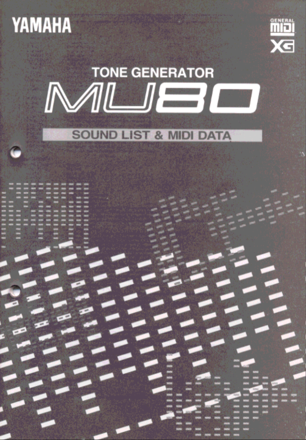
REVERB
No. Effect Type Features
1 NO EFFECT Effect off.
2 HALL1 Concert hall reverb.
3 HALL2 Concert hall reverb.
4 ROOM1 Small room reverb.
5 ROOM2 Small room reverb.
6 ROOM3 Small room reverb.
7 STAGE1 Reverb for solo instruments.
8 STAGE2 Reverb for solo instruments.
9 PLATE Simulated steel plate reverb.
10 WHITE ROOM Distinctive short reverb with initial delay.
11 TUNNEL Simulation of long tunnel-like space.
12 CANYON Long, cavernous reverb.
13 BASEMENT Small, highly reflective room reverb.
CHORUS
No. Effect Type Features
1 NO EFFECT Effect off.
2 CHORUS1 Conventional chorus program with rich, warm chorusing.
3 CHORUS2 Conventional chorus program with rich, warm chorusing.
4 CHORUS3 Conventional chorus program with rich, warm chorusing.
5 CELESTE1 Three-phase LFO for richer, more pronounced chorusing.
6 CELESTE2 Three-phase LFO for richer, more pronounced chorusing.
7 CELESTE3 Three-phase LFO for richer, more pronounced chorusing.
8 FLANGER 1 Pronounced three-phase modulation with slight metallic sound.
9 FLANGER 2 Pronounced three-phase modulation with slight metallic sound.
10 SYMPHONIC Exceptionally rich & deep chorusing.
11 PHASER Pronounced, metallic modulation with periodic phase change.
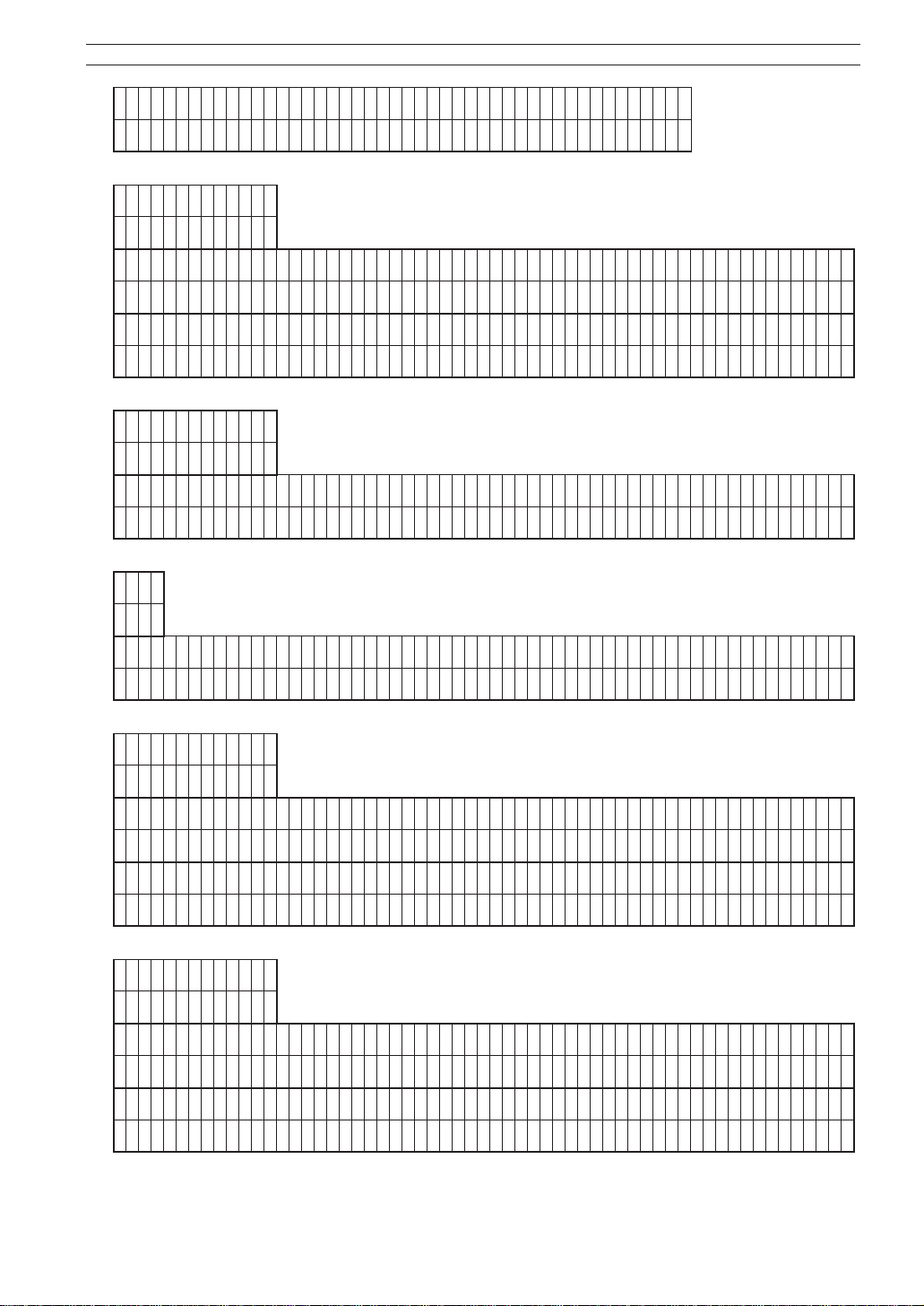
VARIATION
No. Effect Type Features
1 NO EFFECT Effect off.
2 HALL1 Concert hall reverb.
3 HALL2 Concert hall reverb.
4 ROOM1 Small room reverb.
5 ROOM2 Small room reverb.
6 ROOM3 Small room reverb.
7 STAGE1 Reverb for solo instruments.
8 STAGE2 Reverb for solo instruments.
9 PLATE Simulated steel plate reverb.
10 DELAY L,C,R Three independent delays, for the left, right and center stereo positions.
11 DELAY L,R Initial delay for each stereo channel, and two separate feedback delays.
12 ECHO Stereo delay, with independent Feedback Level controls for each channel.
13 CROSS DELAY Complex effect that sends the delayed repeats “bouncing” between the left and right channels.
14 ER1 Early reflections only.
15 ER2 Early reflections only.
16 GATE REVERB Gated reverb effect, in which the reverberation is quickly cut off for special effects.
17 REVERSE GATE Similar to Gate Reverb, but with a reverse increase in reverb.
18 KARAOKE1 Deep echo effects, suited especially for Karaoke-type vocals.
19 KARAOKE2 Deep echo effects, suited especially for Karaoke-type vocals.
20 KARAOKE3 Deep echo effects, suited especially for Karaoke-type vocals.
21 CHORUS1 Conventional chorus program with rich, warm chorusing.
22 CHORUS2 Conventional chorus program with rich, warm chorusing.
23 CHORUS3 Conventional chorus program with rich, warm chorusing.
24 CELESTE1 Three-phase LFO for richer, more pronounced chorusing.
25 CELESTE2 Three-phase LFO for richer, more pronounced chorusing.
26 CELESTE3 Three-phase LFO for richer, more pronounced chorusing.
27 FLANGER 1 Pronounced three-phase modulation with slight metallic sound.
28 FLANGER 2 Pronounced three-phase modulation with slight metallic sound.
29 SYMPHONIC Exceptionally rich & deep chorusing.
30 ROTARY SPEAKER Rotary speaker simulation. Rotation speed can be controlled using AC1 (Assignable Controller 1).
31 TREMOLO Rich Tremolo effect with both volume and pitch modulation.
32 AUTO PAN Several panning effects that automatically shift the sound position (left, right, front, back).
33 PHASER Pronounced, metallic modulation with periodic phase change.
34 DISTORTION Hard-edge distortion.
35 OVERDRIVE Mild, warm distortion.
36 AMP SIMULATOR Simulated guitar amplifier sound.
37 3BAND EQ(MONO) Mono EQ, with Low, Mid and High band controls.
38
*2BANDEQ(STEREO)
Stereo EQ program with low and high frequency controls; ideal for tweaking drum parts. (Cannot be used with A/D input.)
39 AUTO WAH(LFO) Repeating filter sweep “wah” effect; also serves as pedal wah (with AC1).
40 PITCH CHANGE Independent left, right channel pitch change.
41 AURAL EXCITER Enhances the sound by giving it greater definition, presence and clarity.
42 TOUCH WAH Wah effect that varies filter sweep according to input level (or touch); also serves as pedal wah (with AC1).
43 TOUCH WAH+DIST Same as Touch Wah, but with added Distortion.
44 COMPRESSOR Affects the dynamics of the sound by smoothing out the high-volume peaks and soft-volume dips.
45 NOISE GATE Eliminates any noise or hum in the signal.
46 THRU Effect bypass; no effect applied.
*2BAND EQ(STEREO) voice cannot be used with A/D input.
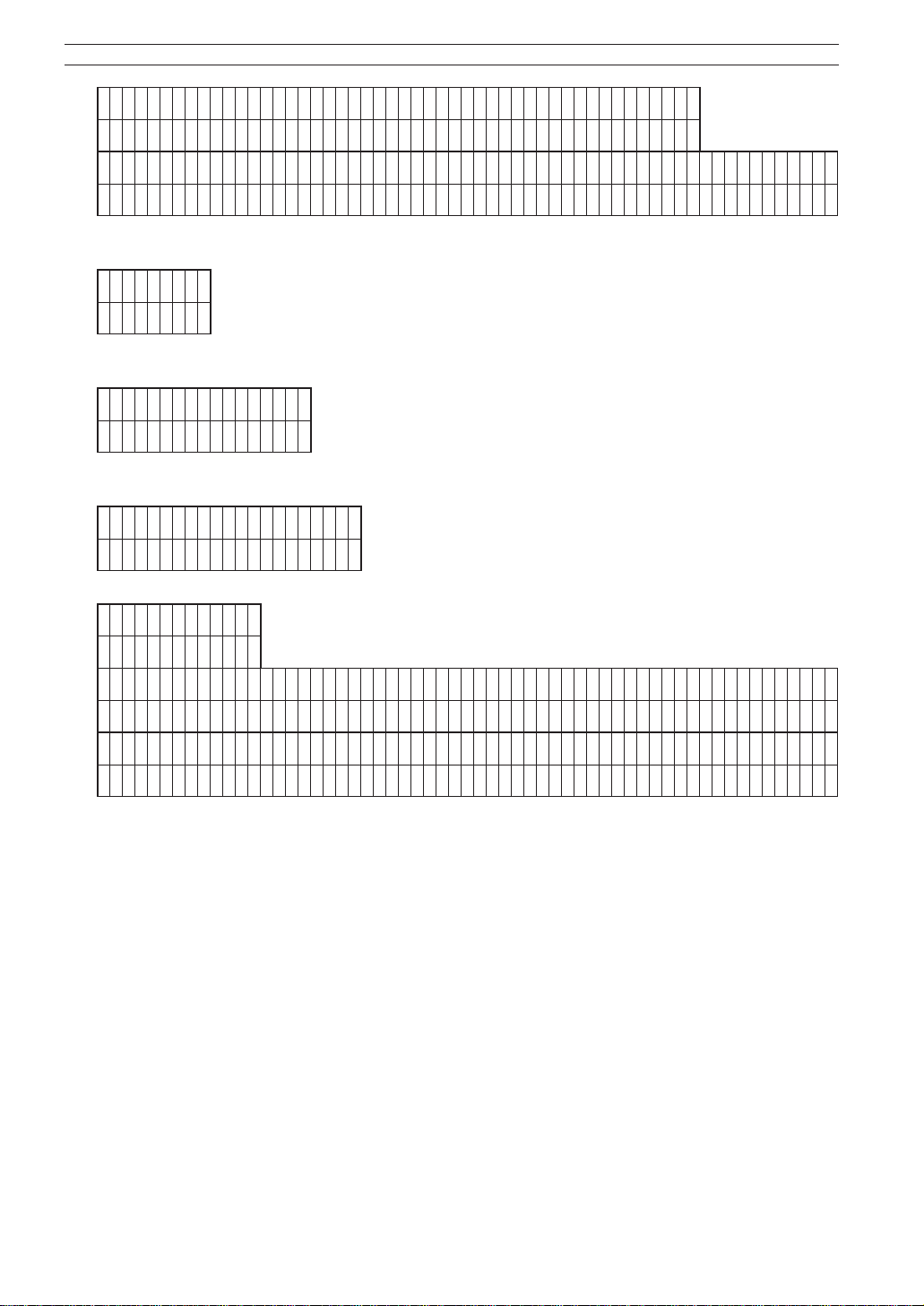
DISTORTION
No. Effect Type Features
1 THRU Effect off.
2 DISTORTION Hard-edge distortion.
3 OVERDRIVE Mild, warm distortion.
4 3BAND EQ(MONO) Mono EQ, with Low, Mid and High band controls.