manuals.online logo
Brands
  1. Home
  2. •
  3. Brands
  4. •
  5. Yamaha
  6. •
  7. Recording Equipment
  8. •
  9. Yamaha TX-7 User manual

Yamaha TX-7 User manual

Other manuals for TX-7

5

Other Yamaha Recording Equipment manuals

Yamaha MD4S User manual

Yamaha

Yamaha MD4S User manual

Yamaha CS6R Instruction Manual

Yamaha

Yamaha CS6R Instruction Manual

Yamaha Audiogram6 User manual

Yamaha

Yamaha Audiogram6 User manual

Yamaha DSP-100 User manual

Yamaha

Yamaha DSP-100 User manual

Yamaha EQ-500U User manual

Yamaha

Yamaha EQ-500U User manual

Yamaha CDR400At User manual

Yamaha

Yamaha CDR400At User manual

Yamaha TQ5 User manual

Yamaha

Yamaha TQ5 User manual

Yamaha CRW2260t Series User manual

Yamaha

Yamaha CRW2260t Series User manual

Yamaha DP-U50 User manual

Yamaha

Yamaha DP-U50 User manual

Yamaha QX 21 User manual

Yamaha

Yamaha QX 21 User manual

Yamaha Steinberg MR816SCX User manual

Yamaha

Yamaha Steinberg MR816SCX User manual

Yamaha MCX-C15 - MusicCAST Network Audio Player User manual

Yamaha

Yamaha MCX-C15 - MusicCAST Network Audio Player User manual

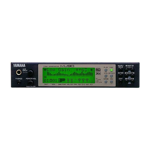
Yamaha MU90 User manual

Yamaha

Yamaha MU90 User manual

Yamaha CDR1000 User manual

Yamaha

Yamaha CDR1000 User manual

Yamaha SFGII User manual

Yamaha

Yamaha SFGII User manual

Yamaha QX-7 User manual

Yamaha

Yamaha QX-7 User manual

Yamaha SPX990 User manual

Yamaha

Yamaha SPX990 User manual

Yamaha 01V96i User manual

Yamaha

Yamaha 01V96i User manual

Yamaha MagicStomp User manual

Yamaha

Yamaha MagicStomp User manual

Yamaha DR100 User manual

Yamaha

Yamaha DR100 User manual

Yamaha FX770 User manual

Yamaha

Yamaha FX770 User manual

Yamaha MT44D User manual

Yamaha

Yamaha MT44D User manual

Yamaha TX-216 User manual

Yamaha

Yamaha TX-216 User manual

Yamaha DP-U50 User manual

Yamaha

Yamaha DP-U50 User manual

Popular Recording Equipment manuals by other brands

ThermoFisher Scientific Dionex DRS 600 Installation checklist

ThermoFisher Scientific

ThermoFisher Scientific Dionex DRS 600 Installation checklist

Shure ANIUSB-Matrix user guide

Shure

Shure ANIUSB-Matrix user guide

Nady Audio HE-1 user guide

Nady Audio

Nady Audio HE-1 user guide

AUDAC APM 01 User manual & installation guide

AUDAC

AUDAC APM 01 User manual & installation guide

Teac GF-350 owner's manual

Teac

Teac GF-350 owner's manual

Fractal Audio MFC-101 MARK III owner's manual

Fractal Audio

Fractal Audio MFC-101 MARK III owner's manual

bmcm USB-OI16 manual

bmcm

bmcm USB-OI16 manual

HHB BurnIT CDR-830 Service manual

HHB

HHB BurnIT CDR-830 Service manual

GE VersaMax IC200CPUE05 manual

GE

GE VersaMax IC200CPUE05 manual

IntesisBox MH-RC-MBS-1 user manual

IntesisBox

IntesisBox MH-RC-MBS-1 user manual

Attero Tech unD4l user manual

Attero Tech

Attero Tech unD4l user manual

Sennheiser UI 765 instruction manual

Sennheiser

Sennheiser UI 765 instruction manual

Sony RCD-W1 Operating Instructions  (primary... Service manual

Sony

Sony RCD-W1 Operating Instructions (primary... Service manual

Roland Planet-P  MKS-10 owner's manual

Roland

Roland Planet-P MKS-10 owner's manual

Roland BOSS GT-PRO Turbostart

Roland

Roland BOSS GT-PRO Turbostart

8x8 Inc Valcom V-2001A manual

8x8 Inc

8x8 Inc Valcom V-2001A manual

Waves SUB Align user guide

Waves

Waves SUB Align user guide

Mitsubishi Electric MAC-334IF-E installation manual

Mitsubishi Electric

Mitsubishi Electric MAC-334IF-E installation manual

manuals.online logo
manuals.online logoBrands
  • About & Mission
  • Contact us
  • Privacy Policy
  • Terms and Conditions

Copyright 2025 Manuals.Online. All Rights Reserved.

FM TONE GENERATOR
TX7
SERVICE MANUAL
CONTENTS
SPECIFICATIONS ... I
HOW TO USE THE TX? 7
Ml Ol DATA FORMAT 9
CONSTRUCTION OF THE TX7 32
TEST PROGRAM .2?
DISASSEMBLY INSTRUCTIONS ....... -&
block diagram < « ,-®
CIRCUIT BOARDS -31
PARTS LIST *34
SI?CE YAMAHA
TX7
SPECIFICATIONS
SoundSource
Simultaneous Ouput Notes ....
Internal Memory
Control Panel
Display
Connection Terminals
Power Requirements ..
Power Consumption ..
Dimensions (WxHxD)
Weight
FM Tone Generator (6 Operators}
Polyphonic; 16 (first note priority)
Monophonic: 1(last note priority)
32 PERFORMANCES
(32 VOICES +32 FUNCTIONS),
32 DX FUNCTIONS
PRESET VOLUME (4)
PROGRAM CHANGE/CASSETTE (2)
STORE/MIDI (2)
FUNCTION (1)
NORMAL/SHIFT (1)
DATA ENTRY (2)
LCD <16 characters x1line)
MIDI IN (DIN JACK SP)
MIDI OUT (DIN JACK 5P)
MIDI THRU (DIN JACK 5P)
CASSETTE (DIN JACK 8P)
OUTPUT (PHONE JACK MONO)
HEAD PHONE (PHONE JACK STEREO)
US &Canadian models: 120V 50/60HZ
General model: 220-240V50/60HZ
US &Canad Ian models :12W
General model; 10W
351 x50 x241 mm
113-5/6" x2” x9-1/2")
2.3 kg (5 lbs. 1oz.)
*All specifications are subject to change without notice.
.—-N
IMPORTANT NOTICE
This manual has been provided for the use of authorized Yamaha Retailers and their service personnel.
It has been assumed that basic service procedures inherant to the industry, and more specifically Yamaha
Products, are already known and understood by the users, and have therefore not been restated.
WARNING: Failure to follow appropriate service and safety procedures when servicing this product
may result in personal injury, destruction of expensive components and failure of the
product to perform as specified. For these reasons, we advise all Yamaha product owners
that all service required should be performed by an authorized Yamaha Retailer or the j
appointed service representative.
IMPORTANT: The presentation or sale of this manual to any individual or firm does not constitute
authorization, certification, recognition of any applicable technical capabilities, or
|establish aprinciple-agent relationship of any form, ;
jThe data provided is believed to be accurate and applicable to the unit(s) indicated on the cover. The
research, engineering, and service departments of Yamaha are continually striving to improve Yamaha
products. Modifications are, therefore, inevitable and changes in specification are subject to change without
notice or obligation to retrofit. Should any discrepancy appear to exist, please contact the distributor’s
Service Division.
|WARNING: Static discharges can destroy expensive components. Discharge any static electricity your
body may have accumulated by grounding yourself to the ground buss in the unit (heavy
gauge black wires connect to this buss).
IMPORTANT: Turn the unit OFF during disassembly and parts replacement. Recheck ail work before
you apply power to the unit.
,
HOW TO USE THE TX7
1. What is the TX7?
The TX7 is atone generator module that can be controlled
by MIDI signals from the DX series, QX1 ,CX5 etc. It is
the equivalent of the DX7 tone generating section.
When connected to aDX7 or DX9, it can act as afunction
memory for the DX7 or DX9, and thus allow you to create
sounds just like aDX1
.
[Features]
•FM tone generation system.
•16 note polyphonic.
•Internal memory: 32 voice data, 32 function data,
stored in pairs. Each voice memory has its own function
memory.
•Individual volume and high and low note limits can be
set for each voice memory. Also, independently of the
voice memory, two volumes may be preset, and recalled
instantly by afront panel switch. This can be used for
muting.
•Besides the TX7's own 32 voice memories and 32 func-
tion memories, it will store 32 function memories for
the DX7. This can be used as an extended function
memory for the DX7.
2.Memory diagram and flowchart of the TX7
The internal memory structure is shown below.
IFM TONE 1
GENERATOR j
JIT
T— “1 PERFORMANCE
jCTST1
|EDt7 buffe*} |edit Buffer}—.. 12VOICE MEMORY 32
1"iLOAD
912TX FUNCTION MEMORY 32
STORE 012DX FUNCTION MEMORY 32
Diagram 1
The internal memory is as follows.
;Voice edit buffer
Function edit buffer
32 voice memories
32 function memories
32 DX function memories
Volume, master tune
The voice and function data of the selected memory
number is loaded into the voice and function buffers.
Then, the voice and function data is loaded into the FM
tone generator, and it is ready to produce sound.
All editing of voice and function data is done on the data in
the buffers.
When the store command is executed, the data in the
buffers is stored into the respective memories.
The data in the function edit buffer will be stored into the
memory that you designate.
3. How the switches work
There are four kinds of switches on the from panel of the
TX7. 0Switches to enter volume and data, 0Switches
that have different operations when in normal or shift
mode, ®Selector switch normat/shift mode, 0Switches
to set function data.
The operation of switches types 0^0is shown below.
Diagram 2
NORMAL MODE: Program change mode
Store mode
Function mode
SH IFT MODE :Cassette mode
MIDI mode
Function mode
When changing from program change or store modes to
cassette or MIDI modes, press MODE switch to change to
SHIFT mode. Then press the cassette or MIDI switch.
When changing the other way back to program change or
store modes, press MODE switch again to change to
NORMAL mode. Then press the program change or store
mode switch.
-1-—2—
TX7
TX7
The diagram below shows the assignment of the TX7's
switches. When you press each switch (left), this message
will appear (right).
TX7 SWITCH ASSIGNMENTS
CCD DISPLAY
-function mooc <
ITunc -w -S3
IPLAy MOOC-r POL* /MONO
>
Ipwang-o-‘2? sn»-iO^T2)
iPOR'r*i^enPOLV ^RTN/CLW.'. PHT/GlS*.
]Mien MONO iFia. FGO PAT/GLS)
:normal mooc
j
sc «p.o/n. aio/i v£.0/ 1)
IAT« 0-15' »<0/n. AtO/H £.0/1 :
jATTCMjAftON
^0* S*UNC*: f32'
*copy >
EX»r *0*CE OUT ?
V»Ct T^ANSMfi 7
•OCC SF*T *
The list below shows the abbreviations used with the TX7,
and their full meaning.
TX7 AMftEVIATIONS
PvrtfTW MOOC
RNG-(0-1?}. STP-(0~12> •PITCH SCNO WHEEL RAN0E-(O- 1J). STEP-!0- IS)
popta<atn/flwi (p*t/ols>
PORTA(FUL/FGO) (PRT/OLS)
POWTAACNTO (ACTAPi/FOLU** ). (PO*TM*mO/tkJWA*»)
PORTAMENTO (FULL T1*/FW0£RED>. (PCRTAA«NT0/0UftftAi®0)
A4W.{0-1S).P<0/1>. «(0/1) E(0/l) :MODULATION WHEEL RANOC-IO- IK PITCH (OFF/WW.
AAWUTUOE (OFF/ON). ES BUS (OFF/W)
FC-(O-ltt). P(0/1). A<0/t> £(0/1>
00 -(0- 1ft) P<0/1). A(0/1) £(0/1)
FOOT CONTROLLER RANOC-W- IS). PfrCHtOFF/ON)
AIWAJTUCEIOFF/OH). EO BUS (OFF/ON)
lBREATH CONTROLLER AAH0C-(0- IS). PITCH(GN).
AT-(O-tft). P«vift) A«V1 ). £(0/1)
AMPLITUDE (0FFAJN1 £0 BUS OFF/ON)
:AFTER TOUCH RANQE-iS- IS). PITCMiOPF/CH)
AJW’LT’JOE (OFF/ON) £0 BUS (OFF/OH)
MOOC
TYOKE WTULtfET
li
'
|[ oentry rcv. (on/offi .DATA ENTRY RECEIVE ON/OFF)
0ENTRY VOL [ON/DFF> :DATA ENTRY VOLUAE (ON/OFF)
OIL CHNQ.RCV WVOFF) :CONTROL CHANGE RECEIVE OH/OFF)
cassette mem protect ion/off t
-OAO func» .(Nr -'EKTi
.OAD CASSCTTC 1
•When you press avoice select switch on the DX7,
program change data is sent from MIDI OUT. The TX7
will load voice and function data for the selected pro-
gram number into its edit buffers 0
At the same time, the DX function data for that pro-
gram number will be sent from the TX7 MIDI OUT as
one performance bulk data (2)
•The same thing will happen if you select aprogram
number using the TX7 switches.
In this way, by using the program select switches of
either the TX7 or the DX7, you can change both func-
tion memories simultaneously, simulating the operation
of the DX1 performance memory.
2) Individual mode
•In the setup shown in diagram 3, when you press aDX7
voice select switch, program change data will be sent
from MIDI OUT.
The TX7 will send the DX function data for that pro-
gram number out of its MIDI OUT as one performance
bulk data (2)
However, the TX7 voice and function will not change,
ie 0will not occur.
•In the setup shown in diagram 3, when you change the
TX7 voice number, the TX7 will load the selected voice
and function data into its buffers 0
However, DX function data will not be sent from MIDI
OUT, ie 0will not occur.
In this way, you may select programs independently for
the TX7 and DX7, and change voice and function
memories as apair, thus expanding the possibilities of
combinations.
4. Program change mode
This is the mode to select voices. Use this mode when play-
ing the TX7. This mode has the following two choices.
•Combined mode {when power is switched on, it will be
in this mode.)
•Individual mode
Select voices using the [YES +1 3[NO -1 ]switches.
1) Combined mode
Here is adiagram showing the data flow when aDX7 is
connected to MIDI IN.OUT when the TX7 is in combined
mode.
_
TX7 INDIVIDUAL COMBINED
MODE MODE
Voice memory 12 35!6:: 31 72 TX7
output
!1
Function memory <z3563i 32 sound
DX function ,^2!3iv,
memory iVi
i . -
iDX7
output
0X7 sound
Voice memory, 1,i 2.! 3,,56 ,31 ,32 ,
Diagram 4
3) Editing voices of the TX7
You may edit TX7 voices by sending the voice data from
the TX7 to an editing device (such as the DX7), editing it,
and sending the edited voice data back to the TX7.
12DX FUNCTION MEMORY 32
Diagram 5
0Turn the TX7 Data Entry Receive ON. (MIDI mode)
0Set the editing device to accept TX7 voice data. (For
example, using the DX7, set the internal memory pro-
tect OFF, and set system information to AVAIL.)
0When the TX7 display shows edit voice out, press [YES
+1 ]to transmit the voice data in the edit buffer.
®Put the editing device in edit mode, and edit the voice.
This will change the data in the TX7 voice edit buffer
(one parameter at atime). At present (January 1985),
possible editing devices are DX7, DX9, DX1, YRM13.
*When in program change mode (combined mode, indi-
vidual mode), if the DX7 system information is AVAIL
and you press avoice select switch, 1voice bulk data will
be sent from MIDI OUT, and the data in the TX7 voice
edit buffer will be replaced by the new data from the
DX7.
-3-
TX7
TX7
5. Cassette mode
In this mode, you may store 32 voice and 32 TX function
data, or 32 voice and 32 DX function data onto acassette.
Or, you may load this data from the cassette.
1) Save Saving data onto acassette. Press SAVE/
VERIFY while in shift mode.
®To keep track of data stored on acassette, assign an
index number to the data. When loading, the TX7 will
display this number.
[SAVE NUMBERl—
J
.... Use the [+1] [-1] switches to
”t select anumber 0~127.
Save
number
(D Select the function data you want to save.
1SAVE FUNC?i-_— ... Select using 1+1], [-1] switches.
INTor EXT
12VOICE MEMORY 32]—£
1>2 TX FUNCTION MEMORY 32j
1:2 DX FUNCTION MEMORY 1~32|—
TNT" Save 32 voice data and 32 TX function data.
•This is automatically selected when power is turned
ON.
"EXT" Save 32 voice data and 32 DX function data.
(3) Execute save
[SAVE TAPE? TX *U-.1 .... To save, press [+1]
.
4Save number
[NOW WORKING!! 1.. . .This will take about 45 seconds.
4If you want to abort, press [— 1]
.
[FINISHED!!! |...
.
Save completed.
•Attenuation function data will not be saved on tape.
•Saving the DX7 data together with the TX7 data as a
performance.
1.Set (SAVE FUNCj to INT and save. (Save the TX7
data as in steps (f) ~(D .[TAPE 1}.}
2. Turn the TX7 memory protect OFF.
3. Send 32 DX7 voice data to the TX7. (MIDI TRANS-
MIT)
The 32 TX7 voice memories now hold the DX7
voices.
4. The TX7 will display "MIDI RECEIVED".
5. Change to ["SAVE NUMBERj to distinguish between
DX7 and TX7 data.
6. Set ["SAVE FUNCj to EXT and save. (Save the DX7
data as in steps (T) ~(D [TAPE 2]
)
-—
1
TX-x TX-y
32 VOICE DATA I32 (DX7) VOICE DATA
32 TX FUNCTION DATA 32 DX FUNCTION DATA
2) Verify -Checking to see if data has been correctly
saved. Press SAVE/VERIFY after saving data.
rvER7FY_CASSETTE? |...
4
Press [+1] .
[“NOW WORKING"!! ]. . .
4
|FOUND TX *,.j1
Play the tape. If you want to
quit, press [-1]
.
jSave number
|FINISHED!*! ITape data is OK. If there is a
problem TAPE ERRORj will
be displayed.
3) Protect -Protect memory. Press LOAD/PROTECT.
®Turn off memory protect. When loading from acassette,
receiving 32 voice and 64 performance data via MIDI, or
storing to memory, protect must be turned OFF. When
the power is turned ON, memory protect will be ON.
|MEM PROTECT ON j.... To turn memory protect OFF,
lpress [-1]
.
OFF
4) Load Load data from tape. Press LOAD/PROTECT.
®Select the function data you want to load.
[LOAD FUNC?- ^
-1 Select usino !+l1 f —ll switches
INT or EXT Load 32 TX7 voice
data and 32 TX7
12VOICE MEMORY 32 h- 1NT function data.
CVT Load 32TX7 voice
"data and 32 DX7
function data.
12TX FUNCTION 32
12DX FUNCTION 32
(2) Execute load.
ILOAD CASSETTE? j.... To begin ioad, press [+1]
.
4
jNOW WORKING!! ].... If you want to abort, press (—1 ]
4
.Data has been found.
Save number
1FINISHED!!! _J. ...Finished loading.
*|f you attempt to laod while memory protect is ON, ^MEMO-
RY PROTECT] will be displayed, and you will not be able to
load.
6. Store mode
In this mode you may store data from the edit buffers into
memory.
1) Store TX performance -Store voice and TX function
data in the buffers into the voice memory and TX func-
tion memory you select. Press TX PERF.
®Selecting the memory number to store into.
STR TX PERF?
Memory
number
.Select the memory number using
the [TX PERF) switch.
•Set memory protect OFF.
To store, press [+1]
iFINISHED!!"! |... Voice and TX function data has
“been saved into the memory
number you selected.
The TX7 stores voice and function data as apair. You cannot
save only one or the other.
2) Store DX function - • •Store the function data in the edit
buffer into the DX function memory you select. Press
DX FUNC.
(T) Selecting the memory number to store into.
|STR DX5 FUNC’^j! . . .
Memory
number
.Select the memory number using
the [DX FUNC) switch.
•Set memory protect OFF.
To store, press [+1]
|FINISHED!!! |. ...Function data has been saved into
the DX function memory you
selected.
7. MIDI mode
In this mode, you may set the conditions for MIDI data
reception (MODE), and transmit or initialize voice data
(DUMP/INIT).
1) Setting TX7 MIDI reception condition -Press (MODE).
(T) Control change reception
[CTL. CHNG. RECl_J Select using [+1] [-1]
.
ON or OFF
"ON" •The following control signals will be received.
•Modulation wheel
•Breath controller
•Foot controller
•Portamento time
•Volume (Not the same as volume control
via the data entry slider.)
•Sustain switch
•Portamento switch
"OFF"- •• The above control signals will not be received. I
‘Control change reception is memorized.
(2) Data entry reception
1P, ENTRY RCV.i__I3] .... Select using [+1 ],[-1 )
.
ON or OFF
"ON" The following MIDI signals will be received,
(when editing TX7 voice or function data)
•Data entry
•Increment
•Decrement
"OFF"-- -The above signals will not be received.
‘Data entry reception ON/OFF is memorized.
•This switch and the data entry volume switch cannot both be
ON at the same time. When you set the data entry volume
switch ON, this switch will automatically go OFF.
(D MIDI receive channel.
jMIDI RCV. CH> j11Select using (+1). Ml.
MIDI channel 1~16
•The TX7 MIDI output channel is automatically channel 1.
•The selected receive channel number is memorized.
(4)Omni mode
|OMNI MODE i.,i jSelect using [+1] [-1]
ON or OFF
"ON" The MIDI receive channel setting will have no
effect, and MIDI signals on all channels will be
received.
"OFF"--- Only MIDI signals with the same channel
number as the receive channel setting will be
received.
•Omni mode ON/OFF is memorized.
(§) Data entry volume
iD. ENTRY VOL <1 .... Select using [+1) [-1]
ON or OF F
"ON" •••You may control the TX7'$ volume using the
data entry slider on the DX7, DX9 or DX1
.
"OFF"- -- The data entry slider will not affect the TX7's
volume.
'Data entry volume ON/OFF is memorized.
This switch and the data entry receive switch cannot both be
ON at the same time. When you set the data entry receive
switch ON, this switch will automatically go OFF.
-5- -6-
TX7
TX7
2) Transmitting and initializing voice data -Press (DUMP/
INIT)
0MIDI transmit ... 32 voice and 64 performance data will
be sent from the TX7 MIDI OUT.
jMIDI TRANSMIT? ].. . . Press [+1 ]to transmit.
jNOW WORKING!!
i
..Transmitting data.
fFINISHED!!! 1. , ..Transmission completed.
•When transmit ,.<ig to the DX7, set the 0X7 memory protect
OFF and set system information AVAIL.
•For the data format, see MIDI Data Format 4-8 (32 voice)
and 4-7 (64 performance).
(2) Voice initialize This will set all data in the TX7 voice
and function edit buffers, 32 voice, 32 TX function, and
32 DX function memories to the initial valves shown
in table 1
.
1VOICE INIT? 1. . . Press [+1] to initialize.
iNOW WORKING!! IInitialization in progress.
1FINISHED!!! ]. . . .Initialization completed.
*lf you want to initialize alt
set memory protect OFF. memory to the valves in table 1,
*tf memory protect is ON when you initialize, IMEM. PRO-
TECTED Iwill be displayed, and only the voice and function
buffers will be initialized.
Data that will be initialized
FUNCTI0N VOICE 1
EDIT 0uFFFR -3iT 0trF‘E- j
123WCE MEMORY 32
123TX FUNCTION MEMORY 32
is ON 123ox function memory 32
When memory protect is OFF
Diagram 7
Table 1
<lnitialize data>
VOICE
Algorithm 1
Feedback 0
Pitch 8feet
EG
EG scaling None
Output level OPT 99
OP2-6 0
Modulation 0
Oscillator key sync ON
Transpose C3
LFO Valve Triangle
Speed 35
Delay 0
Pitch modulation sensitivity 3
Pitch modulation depth 0
function
Master tune 440Hz
Play mode POLY
Pitch bend Range 7
Step 0
Portamento Mode RETAIN
Glissando switch PORTAMENTO
Time 0
Modulation wheel Range 8
Pitch 1
Amplitude 0
EG bias 0
Foot controller Range 8
Pitch 0
Amplitude 0
EG bias 0
Breath controller Range 15
Pitch 0
Amplitude 0
EG bias 0
After touch Range 8
Pitch 0
Amplitude 0
EG bias 0
Key limit Lowest C-2
Highest G8
|Attenuation 7
(3) Function copy ••Copy the data in the function edit
buffer to all 32 TX function memories or to all 32 DX
function memories.
(function COPY? |...Press [+11to copy.
i
|FINISHED!!! |
,.. . Finished copying.
•The copying destination is determined by the cassette mode
save function.
"1NT” Copy function edit buffer to all 32 TX function
memories.
"EXT” Copy function edit buffer to all 32 DX function
memories.
•Before you copy, set memory protect OFF.
£* VjICE
ECit 123VOCE MEMORY 32
~\ 123•* FlYPON MEMOS' 32
1rf.E y? ,
123:x s.NC'ON MEMCBV 32
IJN m
-7-
0Edit voice out -Send the voice and function data in the
edit buffers from MIDI OUT.
iEDIT VOICE OUT? |. .,,.Press [+1] to transmit.
("FINISHED!!! ]. ...Data transmitted.
Data is sent in the following order.
1. Function (1 performance bulk).
2. Voice (1 voice bulk).
'When transmitting to the DX7, set the DX7 memory protect
OFF and set system information AVAIL.
8. Function mode
In this mode you may edit the data in the function edit
buffer. Choose the parameter using the [FUNCTION]
switch, and set the valve using the [+1] [—1] switches.
The [FUNCTION] switch will step through the functions
in the order shown in table 2, and in shift mode, will step
in the reverse order. Except for MASTER TUNE, afl
parameters may be set independently for each of the 32
function memories.
Table 2
[PARAMETER]
*1 When POLY, RETAIN (RTN) sus key
FOLLOW (FLW) sus key
When MONO, FINGERED (FGD)
FULLTIME <FUL)
*2 GLISSANDO (GLS) or PORTAMENTO (PRT)
*3 The RANGE for MODULATION, FOOT, BREATH,
and AFTERTOUCH will be displayed on ascale of
0-15. {The same as the DX1 .)
The relation to the DX7 range is shown below.
TX7 012n4T670I: 10 11 12 13 E15
DX7 0.JL 13 13 26 39 46 ss66 72 79 86 99
*4 SW. will be displayed as ON =1, OFF -0.
*5 LIMIT KEY will be displayed as note name C-2 ~G8.
Key limit settings and note production range for the
TX7 is shown below.
LH—L<H
£L7HL—
H
HL1>H
lH !1—^n
MASTER TUNE 'MASTER TUNE J
PLAY MODE ”PLAY MOOE ,J
PITCH WHEEL RANGE 'PW-gNG *(_j. STP
PITCH WHEEL STEP 'PW RNG »^.STP *l_|J
PORTAMENTO MOOE iRTN, FLW. FGD, FULI 'I -PORTA ,it 4j
GLISSANDO SWITCH (GLS. PRT) *2 "PORTA ,:J
PORTAMENTO TIME -PORTA .. ;
MODULATION WHEEL RANGE *3 ~MW •Ji, A0.Ej
PITCH SW *4 "MW «... .P.Q. A^. E^j
AMP SW "MW *, *Pw-. Ail. EujJ
EG RAS SW "MW „P^, A^, EiDi J
FOOT CONTROL RANGE ~FC «U. A,j
PITCH SW -FC *•. PjL A^, Ei_» j
AMP SW 'FC ", PaH, E-_j J
EG BIAS SW "FC Au, Ekj
BREATH CONTROL RANGE "BC ",n. p_, Ai_,, Ei_j J
PITCH SW 'BC Pjl. A^rEw-
AMP SW "BC «P„. Ak, E_* _
EG BIAS SW "BC *. Pw,A^,, EJsi „
AFTER TOUCH RANGE "AT =JI. P_, A^., E,_-
PITCH SW "AT Pti, A^. E. ij
i
j
AMP SW "AT Pi_,, aJ,.
EG RAS SW _AT =. P._, rA^_,. e7 _
jlimit lowest KEY *5 "SP E-H-,_j
:limit HIGHEST KEY “SP L=0•-
:ATTENUATION '6 ”ATTENUATION ,
*6 ATTENUATION is on ascale of 0~7.
The volume may be changed in 8steps, with 7as maxi-
mum and 0as minimum. Settings of the preset volume
switch or MIDI volume data will be adjusted on this
scale.
9. Preset volume
You may raise or lower the volume of the TX7, and estab-
lish 2preset volume levels.
0Raise volume ••• Press the [>] switch, (press and hold}
*The volume will increase on ascale of 0~80 (81
levels), and the dark section of the LCD will increase or
decrease with the volume. When you release the switch,
the volume will stay at that level. The [<] switch has
the same operation.
0Lower volume •• -Press the[<] switch, (press and hold)
®Store volume (LOW) While pressing the [LOW]
switch, set the volume using the [>] [<] switches. Then
release the [LOW] switch.
®Store volume (HIGH) While pressing the [HIGH]
switch, set the volume using the [>] [<] switches. Then
release the [HIGH] switch.
®Recall volume •Press and release the [LOW] or [H IGH]
switch. The volume you preset will be recalled.
-8-
MIDI DATA FORMAT
1. Reception conditions
MIDI IN
SFE
S80
S90
SBO, SOI
SBO. S02
SBO. SO
4
SBO, S05
SBO. $07
SBO, S40
SBO. S41
SCO
SDQ
SEO
SBO, S60
SBO. $61
SBO. S06
SBO. S06
SFO. $43. SOO. SO
2
SFO. S43. SOO. S09
SFO. S43. SOO. SOO
SFO, S43. SOO. SOI
SFO. $43. S10
cro. fi4 3. cso
SBO. S7C
SBO. S7D
SBO. S7E
SBO, S7F
ACTIVE SENSING
NOTE OFF
NOTE ON
MOD. WHEEL
BREATH CONTROL
FOOT CONTROL
PORTAMENTO TIME
VOLUME
SUSTAIN SWITCH
PORTAMENTO SWITCH
PROGRAM CHANGE
AFTER TOUCH
PITCH BENDER
INCREMENT
DECREMENT
DATA ENTRY
DATA ENTRY =Volume
64 PERFORMANCE BULK
32 VOICE BULK
IVOICE BULK
IPERFORMANCE BULK
PARAMETER CHANGE
DUMP ntTOUETST
OMNI OFF
OMNI ON
MONO
POLY
2. Reception data
2-1 Reception Channel, Omni
Using the panel switches, you may select the TX7 MIDI
reception basic channel 1-16 and OMNI ON/OFF ,and store
this in memory. When OMNI OFF, only data with achan-
nel number corresponding to the basic reception channel
will be received, but when OMNI ON, data for, ail channels
will be received.
2-2 Channel Voice Messages
2-2-1 Key OFF
Status 1000nnnnn =channel number.
Note no. 0kkkkkk k k=0(C-2) -- 127 (G8)
Velocity 0vvvvvvvv:ignored
2-2-2 Key ON/OFF
Status 1001nn n nn=channel number
Note no. 0kkkkkkkk-0 (C-2) -127 (G8)
Velocity 0vvvvvvvv =0Key OFF
v-1-127 Key ON
2-2-3 Control change
Status 10 1 1 nnnn
Control No. Occccccc
Control value Ovvvvvvv
(a) Data received when CONTROL CHANGE RECEIVE
SWITCH ON
C-1Modulation
C-2Breath controller
0*4 Foot controller
C-5Portamento time
C=7Volume
C*64 Sustain SW.
C=64 Portamento SW.
(b) Data received when DATA ENTRY RECEIVE SWITCH
ON
C=6Data entry
C=96 Increment
C=97 Decrement
This data will change the voice or function parameter
which has been selected by asystem exclusive mes-
sage.
(c) Data received when DATA ENTRY VOLUME ON
C=6Data entry
The data entry data will be received as volume data.
2-2-4 Program change
Status 1lOOnnnn
Program no. Oppppppp
It will disregard the 2most significant bits of program
no. and select programs 1-32.
This will De received only when the TX7 is in pro-
gram change mode {COMBINED or INDIVIDUAL),
2-2-5 After touch
Status 1 1 01nnnn
Pressure Ovvvvvvv
2-2-6 Pitch bend
Status 1 1 10nnnn
Value (LSB) Ouuuuuuu
Value (MSB) Ovvvvvvv
8bit resolution
2-3 Channel Mode Messages
Status 10 11n n nn
Occccccc
Ovvvvvvv
C=124 V=0 OMNI MODE OFF
C=125 V=0OMNI MODE ON
C=126 V=1MONO MODE ON
C=127 V=0POLY MODE ON
OMNI ON/OFF may also be selected using panel switches.
Whichever signal arrives last has priority.
When the mode is changed, the voice will be dumped and
key assign will be cleared.
2-4 System Realtime Messages
Status 11111110 active sensing
Once this code has been received, sensing will begin. If it
does not receive any data or status for longer than 300 ms,
it will dump voice, clear key assign, set sustain pedal off,
set portamento switch on, and stop sensing.
2-5 System Exclusive Messages
2-5-1 1voice bulk data
Status 11110000
ID 01000011
Substatus/ch OOOOnnnnn* channel number
Byte count 00000001
Byte count 0001 1 011
Data Oddddddd
^j
155 bytes
Oddddddd '
Check sum Oeeeeeee
The 155 bytes of voice data will enter the edit buffer
and the voice of the currently sounding note will
change. Check sum is the lowest 7bits of the sum of
all the data bytes.
-10-
TX7
TX7
!1performance bulk data
Status Mil 0 0 0 0
ID 010 00011
Substatus/ch 00 0 0nn n n
Format no. 0 0 0 0 0001
Byte count 0000000 0
Byte count 010 11110
Data 0ddd d ddd
t
0dd d dd d d
Check sum 0eeeeeee
Out of the 94 bytes, only the data applying to the
TX7 will enter the edit buffer. The function para-
meters of currently sounding notes will change.
Ch Aor Bwill receive the data according to the voice
memory select flag in the data bytes.
2-5-3 64 performance bulk data
Status
ID
Substatus/ch
Format no.
Byte count
Byte count
Data
Check sum
111 1 00 0 0
0100 0 011
OGOOnnnn
0000 0 010
0 0 100000
00000000
Oddddddd
0ddid d d d
Oeeeeeee
4096 byte
The above data can be received only when memory
protect is OFF. When it has been received, the LCD
will show jMIDI RECEIVED If I.Of the 64 perfor-
mances, side Aof the first 32 performances will be
loaded into the function memories of programs 1*32.
Whether the function memories are for the DX or TX
will depend on the LOAD FUNCTION when you
load the data from cassette. (When the power is
turned on, it is be set to TX functions.)
2-5-4 32 voice bulk data
Status
ID
Substatus/ch
Format no.
Byte count
Byte count
Data
11 1 1000 0
01000011
OOOOnnnn
00001001
0 0 10000 0
00000000
Oddddddd
Oddddddd
Check sum 0ee
4096 bytes
The above data can be received only when memory
protect is OFF. When it has beenreceived, the LCD
will show 1MIDI RECEIVED^/] .Voice data of pro-
grams 1-32 will change.
2-5-5 Parameter change
Status 1111 0 0 00
ID OlOOOOtl
Substatus/ch 0001nnnn
Parameter
group no. 0g g
Parameter no. 0pp
Data Odd
ggghh
PPPPP
dddd d
(g =0,1,2,4)
(h =0, 1
)
Voice and function data in the edit buffer will
change.
2-5-6 Dump request
Status 11 110 00 0
ID 01000011
Substatus/ch 0010nnnn
Format no. Of fff f f f (f =0, 1, 2, 9, 125)
When this has been received, the appropriate bulk
data will be dumped from MIDI OUT.
3. Transmission data
Normally, there will be no data transmission. Data will be
transmitted when there is adump request signal from
outside, or through operation of the panel switches. The
transmitted data is voice and function system exclusive
data. Data will always be sent on channel 1
.
3-1 Transmission Conditions
(a) Transmission on dump request
The following 5types of data will be transmitted
according to format No. (f).
f=01voice bulk data
The contents of the voice edit buffer
will be sent.
f=11performance bulk data
The contents of the function edit buffer
will be sent, and bank Aand B will have
identical data.
f=264 performance bulk data
The contents of the TX function memo-
ries 1-32 will be sent.
f=932 voice bulk data
Voice data of programs 1-32 will be
sent.
The above formats are the same for data reception, but
an E0X ($F7) is added at the end.
f=125
Status
ID
Substatus/ch
Format no.
Byte count
Byte count
Data
S
Conditions acknowledge
11110000
0100001 1
00000000
0111110 1
00000000
0001000 0
Oddddddd
Oddddddd
Check sum Oeeeeeee
E0X 11110111
(b) Transmission by panel switch in ^MIDI TRANSMITj
mode
When the display shows [MIDI TRANSMIT?! and you
press the YES/+1 switch, the following data will be
sent.
•32 voice bulk data
•64 performance bulk data
(c) Transmission by panel switch in rcOMBINEDj mode
When in combined mode, if ever you select avoice or it
receives aprogram change signal, the following data
will be sent.
•1performance data
(d) Transmission by panel switch in !INDIVIDUALj
mode
When in individual mode, if it receives aprogram
change signal, the following data will be sent.
•1performance data
<e) Transmission by panel switch in HeDIT VOICE OUTj
mode
When the display shows [EDIT VOICE OUT land you
press the YES/+1 switch, data will be sent in the
following order.
1) 1performance data
2) 1voice data
-11 --12-
4. System exclusive data format
4*1 DX7 VOICE PARAMETER CHANGE (g -0)
Sub-group
Number h
Parameter
Number PParameter Data Notei
0OP6 EG RATE 10-99
1OP6 EG RATE 20-99
2OP6 EG RATE 30-99
3OP6 EG RATE 40-99
4OP6 EG LEVEL 10—99
5OP6 EG LEVEL 20'**99
6OP6 EG LEVEL 30-99
7OPS EG LEVEL 4O'- 99
8OP6 KEYBOARD LEVEL SCALING BREAK POINT 0'—99 *1
90P6 KEYBOARD LEVEL SCALING LEFT DEPTH 0—99
to OP6 KEYBOARD LEVEL SCALING RIGHT DEPTH 0-99
11 OP6 KEYBOARD LEVEL SCALING LEFT CURVE 0-3 *2
12 OP6 KEYBOARD LEVEL SCALING RIGHT CURVE 0-3 •2
13 OP6 KEYBOARD RATE SCALING 0-7
014 OP6 AMPLITUDE MODULATION SENSITIVITY 0-3
15 OP6 KEY VELOCITY SENSITIVITY 0-7
16 OP6 OPERATOR OUTPUT LEVEL 0-99
17 OP6 OSCILLATOR MODE 0-1 *3
18 OP6 OSCILLATOR FREQUENCY COARSE 0-31 •4
19 OP6 OSCILLATOR FREQUENCY FINE 0-99 *4
20 OP6 OSCILLATOR DETUNE 0-14 *5
21 '"*’41 OP5
42-62 OP4
63-83 OP3
84 —1Q4 OP2
105 —125 OP1
126 PITCH EG RATE 10-99
127 PITCH EG RATE 20-99
0(128) PITCH EG RATE 30-99
1(129) PITCH EG RATE 40-99
2(130) PITCH EG LEVEL 10-99
3(131) PITCH EG LEVEL 20-99
4(132) PITCH EG LEVEL 30-99
5(133) PITCH EG LEVEL 40-99
6(134) ALGORITHM SELECT 0-31
7(135) FEEDBACK 0-7
8(136) OSCILLATOR KEY SYNC 0—1
19(137) LFO SPEED 0-99
10 (138) LFO DELAY 0-99
11 (139) LFO PITCH MODULATION DEPTH 0-99
12 (140) LFO AMPLITUDE MODULATION DEPTH 0-99
13 (141) LFO KEY SYNC 0—1
14 (142) LFO WAVE 0—5*6
15 (143) LFO PITCH MODULATION SENSITIVITY 0-7
16 (144) TRANSPOSE 0-48 Concert
17(145) VOICE NAME 1
C
j
ASCII pitch at 24
|26 (154) IVOICE NAME 10 ASCII
r1I27 ft 55)
28(156)
IOPERATOR ON/OFF
OPERATOR SELECT xeeeeee
0-5 *7
*8
MBREAKPOINT
BREAK POINT 01234515 27 39 51 63 75 87 99
MIDI NOTE *21 22 23 24 25 26 36 48 60 72 84 96 108 120
NOTE At A,# Bi Co C0#Do C, C2Hc3c4C< c6c? Cs
KEYBOARD LEVEL!SCALWJG CURVE
0123
CURVE -LIN -EXP +EXP +LIN
*3 OSCILLATOR MODE
“0 "frequency ratio
"1”fixed frequency
*4 FREQUENCY COARSE FINE
i) For Frequency Ratio
When FINE =0
COARSE 01210 30 31
FREQUENCY RATIO 0.5 12310 30 31
When COARSE =1
FINE 012310 50 99
FREQUENCY RATIO 1.00 1,01 1.02 1.03 1.10 1.50 1.99
ii) For Fixed Frequenc
When FINE -0
Y
COARSE 0123456731
FREQUENCY (Hz) 110 100 1000 110 100 1000 1000
When COARSE =0
FINE 01234510 20 50 99
FREQUENCY (Hz) 1.000 1.023 1.047 1.072 1.096 1.122 1.259 1.585 3.162 9.772
DETUNE
012345678910 11 12 13 14
DETUNE -7 -6 -5 -4 -3 -2 -1 01234567
LFO WAVE
012345
WAVE TRIANGLE SAW DOWN SAW UP SQUARE
n__j
SINE SAMPLE/HOLD
*7 OPERATOR ON OFF
Bit bSb4b3b2b, bo
OP OP1 OP2 OP3 OP4 QP5 OP6
Bit Map
"0"...OFF "1... ON
*8 OPERATOR SELECT
02345
OPERATOR OP6 OP5 OP4 OP3 OP2 OP1
-13--14-
TX7
TX7
4-2 DX PERFORMANCE PARAMETER CHANGE (g *1) (h =0)
Parameter
Number PParameter Data Notes
0
1SOURCE SELECT 1—16 *3
2POLY/MONO 0-1
3PITCH BEND RANGE 0-12
4PITCH BEND STEP 0-12
5PORTAMENTO TIME 0-99
6PORTAMENTO/GLISSANDO 0-1
7PORTAMENTO MODE 0-1 •1
8
9MODULATION WHEEL SENSITIVITY 0-15
10 MODULATION WHEEL ASSIGN 0-7 *2
11 FOOT CONTROLLER SENSITIVITY in
7
o
12 FOOT CONTROLLER ASSIGN 0~7 *2
13 AFTER TOUCH SENSITIVITY 0-15
14 AFTER TOUCH ASSIGN 0-7 *2
15 BREATH CONTROLLER SENSITIVITY in
7
o
16 BREATH CONTROLLER ASSIGN 0-7 *2
17
18
19
20
21
22
23
24
25
26 AUDIO OUTPUT LEVEL ATTENUATOR 0-7
27
28
29
30
31
32
33
34
i
63 Concert
64 MASTER TUNING 0-127 pitch at 64
*1 PORTAMENTO MODE
"0"...sustain*key pitch retain
"1"...sustain-key pitch follow
*2 EFFECT ASSIGN
Bit 02 bi o0
ASSIGN EG BIAS AMPLITUDE PITCH
*3 SOURCE SELECT
Corresponds to RECEIVE BASIC CHANNEL 1-16.
—15—
4-3 DX7 FUNCTION PARAMETER CHANGE {g =2)(h *0)
Parameter
Number PParameter Data Notes
64 POLY/MONO 0-1
65 PITCH BEND RANGE 0-12
66 PITCH BEND STEP 0-12
67 PORTAMENTO MODE 0-1
68 PORTAMENTO/GLISSANDO 0-1
69 PORTAMENTO TIME 0-99
70 MODULATION WHEEL SENSITIVITY 0-99 *1
71 MODULATON WHEEL ASSIGN 0-7
72 FOOT CONTROLLER SENSITIVITY 0-99 *1
73 FOOT CONTROLLER ASSIGN 0-7
74 BREATH CONTROLLER SENSITIVITY 0-99 •1
75 BREATH CONTROLLER ASSIGN 0-7
76 AFTER TOUCH SENSITIVITY 0-99 *1
77 AFTER TOUCH ASSIGN 0-7
*1 EFFECT SENSITIVITY
Data is received on arange of 0^99 and stored on arange of 0~15.
4-4 TX FUNCTION PARAMETER CHANG E(g -4) (h *1)
Parameter
Number PParameter Data Notes
0DATA ENTRY RECEIVE SWITCH 0, 1
1CONTROL CHANGE RECEIVE SWITCH 0, 1
2DATA ENTRY VOLUME SWITCH 0. 1
3COMPUTE COMMUNICATION SWITCH 0, 1
4COMBINED (0) OR INDIVIDUAL 11) o, 1
5NOTE LIMIT LOW 0-127
6NOTE LIMIT HIGH 0-127
7MEMORY PROTECT OFF/ON 0, 127
11 LOAD FUNCTION SELECT INT/EXT 0, 127
*1 When data 1is received, COMBINED MODE, CONTROL CHANGE RECEIVE, DATA ENTRY RECEIVE will be set, and 1performance data will
not be sent.
When data 0is received, COMBINED MODE, CONTROL CHANGE RECEIVE, DATA ENTRY OFF will be sent, and 1performance data will be
sent.
4-5 1VOICE BULK DATA
155 bytes of data. For the data format, see 0—154 of 4-1.
-16-
4-6 1PERFORMANCE BULK DATA (f -1)
Parameter
Number PParameter Data Notes
0
1
2VOICE APOLY/MONO 0-1
3VOICE APITCH BEND RANGE 0—12
4VOICE APITCH BEND STEP 0—12
5VOICE APORTAMENTO TIME 0-99
6VOICE APORTAMENTO/GLISSANDO 0-1
7VOICE APORTAMENTO MODE 0-1
8
9VOICE AMODULATION WHEEL SENSITIVITY 0-15
10 VOICE AMODULATION WHEEL ASSIGN 0-7
11 VOICE AFOOT CONTROLLER SENSITIVITY 0-15
12 VOICE AFOOT CONTROLLER ASSIGN 0-7
13 VOICE AAFTER TOUCH SENSITIVITY in
7
o
14 VOICE AAFTER TOUCH ASSIGN 0-7
15 VOICE ABREATH CONTROLLER SENSITIVITY 0-15
16 VOICE ABREATH CONTROLLER ASSIGN 0-7
17
18
19
20
21
22
23
24
25
26 VOICE AAUDIO OUTPUT LEVEL ATTENUATOR 0—7
27
28
29
30
iVOICE B
59
60
61 VOICE MEMORY SELECT FLAG 0—1
62
63
64 PERFORMANCE NAME 1ASCII
65 PERFORMANCE NAME 2ASCII
llASCII
92 PERFORMANCE NAME 29 ASCII
93 PERFORMANCE NAME 30 ASCII
4-7 64 PERFORMANCE BULK DATA (f =2)
Data are listed in order for the 64 performances in units of 64 bytes (64 performance). The TX7 uses the first 32
performance groups.
Address 6543210 Parameter Data Parameter Data 1
0p/mI JVOICE APOLY/MONO 0-1 1
0-12
1PBS(LO) nPBR 1VOICE AP. BENO STEP 0-12 PITCH BEND RANGE
2PTIM VOICE APORTA. TIME 0-99 PORTAMENTO/GLISSANDO
31M1GL VOICE APORTA. MODE 0-1 0—1
4MWA MWS VOICE AMOD. WHEEL ASN. 0-7 MOD. WHEEL SENS. 0-15
5FCA FCS VOICE AFOOT CONT. ASN. 0-7 FOOT CONT. SENS. 0-15
6ATAATS VOICE AAFTER TOUCH ASN. 0-7 AFTER TOUCH SENS. 0-15
7BCA BCS VOICE ABREATH CON ASN. 0-7 BREATH CON. SENS. 0-15
8
9
10 !
11
12
13
14 jATN VOICE AATTENUATION 0-7
15 PBS
(HI) VOICE APITCH B. STEP (MSB)
16
i
31
VOICE B
32 |VMS |KMOD VOICE MEMORY SELECT 0-1 KEY ASSIGN MODE 0-2
33
34 PNAM 1PERFORMANCE NAME 1ASCII
lASCII
63 PNAM 30 PERFORMANCE NAME 30 ASCII
65
'
43210
With the Key Assign in Single mode (KMOD -0) VOICE Aor Bare loaded with VMS.
With Key Assign in DUAL, SPLIT (KMOD =1,2), VOICE Ais always loaded.
—17— -18-
TX7