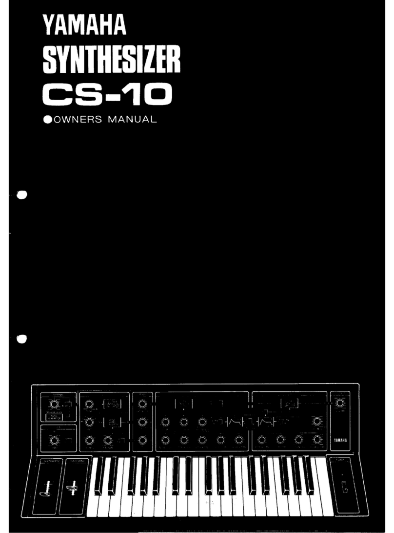
Yamaha CS-10 User manual


SYNTHESIZER CS-10
We thank you very much for your purchase of our YAMAHA Synthesizer CS-10.
CS~10 is asynthesizer developed based on YAMAHA's superior technology and rich
experience cultivated over the years with YAMAHA Electone Organs and by giving
full play to latest IC technology.
EXTERNAL
TRIGGER LEVEL (page 12)
Adjusts trigger level produced by
EXTERNAL terminal iriput.
EXT/NOISE (pages 7, 12)
Aswitch for effecting switchover
between EXTERNAL terminal
input and noise.
LFO
•SPEED (page 8)
Adjusts the frequencies of LFO
(tow frequency osciilator).
•^/ \\ Sine/saw-tooth (Page 8)
Effects switchover between the
wave forms of the LFO.
is J
vco
TUNE (Page 8)
Used for adjusting intervals.
Tuning is to be carried out after about
30 minutes have past, when the inter-
val have stabilized, following switch-on
of power.
FEET (Page 8)
Shifts over sound range of keyboard.
LFO MOD
Modulates VCO with LFO (low fre-
quency oscillator).
PW/PWM control (Page 8)
Depending on how the PW/PWM switch
is positioned, functions as aPM, or
PWM control.
PW: By changing the putse width of
the square wave, becomes a
sound source other than that of
symmetrical square waves.
PWM :Changes the pulse width periodi
calty.
PM/PWM switchover switch
Effects switchover between PW and
PWM.
MIXER
•EXT/NOISE
K
PL
Saw-tooth
wave.
Square wave
Selects the sourf^
source, by adjust-
ing the respective
levels and mixing
them. (Page 7)
PORTAMENTO
Sets the shift time
for "PORTAMENTO"
effect.
(Page 11)
JK

VCF
HPF/BPF/LPF (Page 9)
Selects the filter type.
LFO MOD (Page 10)
Modulates VCF with LFO.
CUTOFF FRO. (Page 9)
Makes the basic tone.
RESONANCE (Page 9)
Further emphasizes the tone produced by
the CUT OFF FRO.
INITIAL LEVEL
ATTACK LEVEL
ATTACK TIME (A)
DECAY TIME (D)
RELEASE TIME (R)
Produces the VCF envelope.
NORMAL/TIME X5
Expands the time for "A",
5times the normal time.
Pages 9and 10)
(Page 10)
'D" and "R" to
TRIGGER (Page 10)
KBD: For ordinary keyboard playing
this KBD-side is to be used.
EXT. Used with external signals.
Trigger Indicator
Trigger signals used tor controlling
EG-VCF and EG-VGA cause this indi-
cator to light up.
VGA
•HOLD/EG (Page 10)
When set to HOLD, will cause
signals to pass the EG/VCA.
•LFO MOD (Page 11)
Modulates VCF with LFO.
•ATTACK TIME •DECAY
TIME •SUSTAIN LEVEL
•RELEASE TIME (Pages 10& 11)
Produces envelope for VGA.
•NORMAL/TIME X 5 (Page 11)
Increases the time of "A",
"D" and "R" to 5times the
normal one.
OUTPUT
•VOLUME
(Page?)
This is a
control
for over-
all volume
adjust-
ment.
VOLTAGE
CONTROLLED
FILTER 3I(
VOLTAGE
CONTROLLED
AMPLIFIER
OUTPUT
HI.-
CUT OFF FRO RESONANCE
^___^_^ EG Is
^z:^ Af°-7|J"',r'i3 Lj J2:::cAn=,„^
--S ''^ 5S-^ "• 1S'~'LS-
?L ATTACK LEVEL ATTACK TIME DECAY TIME RELEASE TIME
-L S
—
f>—L0—' ^10 S-
ATTACK TIME DECAY TIME SUSTAIN LEVEL RELEASE TIME
YAMAHA
POWER
POWER
INDICATOR
POWER
SWITCH
e

WHAT IS ASYNTHESIZER
Unlike other musical instruments, the synthesizer
has no fixed sound of its own. Thus, before playing it,
it is necessary to make the sounds. But with the synthe-
sizer you will be able to make, with your own hands
and by synthesizing sounds, anew type of sounds that
can never be made by any other muscial instrument.
THE THREE ELEMENTS OF SOUND
How does asynthesizer make sounds? Before ex-
plaining the arrangement of the synthesizer, let us
consider what kind of properties sound has.
Sound produced by such muscial instruments as the
piano and guitar has an interval and sound level, accord-
ing to the keyboard or chord used. It is possible to
change the intervals by changing the length of the
chord for the portion that is vibrating. In this case, the
chord's number of vibrations per second also changes.
The chord will vibrate more slowly, the lower the
interval becomes. In this way, it is possible to express
the difference in intervals by the number of vibrations
(frequencies).
Interval
Bass sounds
Treble sounds
wwwv
However, between the sounds of apiano and a
guitar, there is adifference in tone even when both
sounds are of the same interval: no one will mistake
the tone of the piano from that of aguitar. This is
because there is adifference in the way the chords
vibrate (the vibration wave form), due to the
difference in the arrangement by which the sounds
are made to generate, and because of the difference
in the shape and size of the musical instruments.
Tone difference Tone difference is reflected in wave form.
Furthermore, even when both the interval and tone
quality are the same there is adifference in sound, as
when the same key of the piano is hit in aforcible
manner and agentle manner, it would be easy to
o
discern the two sounds from each other because of
the magnitude (volume) of the sound. This is because
adifference will be produced in the size and amplitude
of the chord vibrations, due to the intensity with which
the chord has been struck.
In this way, sounds produced by musical instruments
have such elements as intervals, tone and volume,
whose differences render the sound with certain charac-
teristics. These elements are referred to as '*the three
elements of sound", which may be also considered as
being the difference in the frequencies, wave forms and
amplitude.
CHANGES WITH TIME IN SOUNDS
However, the elements which render sounds with
certain characteristics are not confined to these three.
Taking the piano for example, the volume will reach
maximum the instant the key is hit, then will decrease
gradually. When the finger is released from the key-
board, the sound will fade out. In the case of the organ,
the action of depressing the keyboard will cause the
volume to rise to acertain level, which will be retained
for the duration the key is depressed. The sound will die
away when the fingeixis released from the key.
Envelope Maximum volume ^Envelope
(Such lines do not
really exist.)
K£r ON K£r OFF
Further, in such muscial instruments as the trumpet,
the harmonic spectrum changes together with the
change in volume. The tone changes too, along with
the passage of time.
Thus, such sounds as those of musical instruments
undergo deUcate changes from the time the sound is
generated to the time it fades away. The mode in which
sound changes with time is known as "envelope".
HARMONICS
What must we do in order to produce electrically
sounds that have the three elements of sound, that is,
the intervals, tone and volume, and which vary with
time (has an envelope). Before going into the matter,
let us view sound again from adifferent angle.
As regards the vibration wave forms by which the
tone is determined, it is known that any given wave
form can be measured by using the sine wave as a
measure. In other words, aU wave forms can be
analyzed into alarge number of sine waves. For ex-
ample, let us overlap, over asingle sine wave, wave
forms having an integral multiple number of vibrations.
c
o
such as 2-fold, 3-fold, and so on. You will see that the
wave form will gradually come to resemble asaw-tooth-
like wave form. In addition to this, you will see that
this saw-tooth wave form has acycle similar to that of
the sine wave that has been used as the basis .This sine
wave that has the basic cycle is referred to as the funda-
mental sound and the sine waves of harmonic over-
tones as the harmonics. In the case of musical instru-
ments, the way in which harmonics are contained in
sounds will depend on the arrangement by which sounds
are caused to generate. When we discuss the difference
in tones (wave forms), it is the same as discussing what
kind of harmonics the sounds contain
.
Saw-tooth wave Wave form obtained by adding
harmonics of the 2nd -10th to
fundamental wave.
Wave form obtained by adding
the 2nd harmonics to funda-
mental wave.
Wave form obtained by adding
the 2nd and 3rd harmonics to
fundamental wave.
VCF renders the harmonic spectrum with characteri-
stics, by varying the cut-off frequency.
Wave form variation Filter (LPF) Wave form changes.
Harmonic structure variation
r
Level
Harmonics t
!,Level
h^
f'
Level Disappears by
'being cut off.
Fundamental Cut off frequency
In addition to adjusting the cut-off frequencies by
means of aknob, the tone is caused to undergo achange
with time (from the time the sounds generate to the
time they die away) to give it an "envelope''. This is
accomplished by effecting control on the filter's cut-off
frequencies by means of the envelope generator.
VGA
The VCA block functions to give volume an envelope.
The mode of volume starting from the generation
(positive edge) of the sound, up to the point the sound
fades away leaving reverberations is produced by con-
trolling the envelope generator's A.D. and S.R., which in
turn, controls the amplification degree of the VCA
amplifier.
STRUCTURE OF SYNTHESIZER
In the synthesizer, sounds are synthesized by effect-
ing control on the four properties of sound (the three
elements of sound plus the envelope), dividing control
into 4blocks.
Control of intervals is effected by the VCO, that of
harmonic spectrum by the VCF, that of volume by the
VCA and that of envelope by the EG (envelope gene-
rator). The following describes the controls by each
block.
VCO
The VCO block produces asound source of fre-
quencies corresponding to the intervals of the keyboard.
The sound source wave forms produced by the VCO
consists of such waves as saw-tooth waves and square
waves that include many harmonics in aregular manner.
These waves are oscillated, using an electrical circuit.
VCF
The VCF block makes the tone, by changing the
harmonic spectrum of the sound sources by cutting, or
emphasizing, apart of the harmonics by passing the
sound sources through filters. The boundary between
the portion that passes through the filter and the portion
that is cut off is known as the cut-off frequency. The
VCF signals Envelope generator VCA output
The intervals oscillated by the VCO reach the VCF
where they undergo achange with regard to their
harmonic spectrum by being passed through afilter.
These signals rendered with certain tone characteristics
are given avolume envelope at the VCA and are fed out.
In this way, all elements of the properties of sound are
controlled electrically, by utilizing the three elements of
sound and the envelope. The synthesizer has, in addition
to the blocks described, other blocks such as the LFO
that renders delicate changes to the sounds. But in this
case, too, the job is performed by controlling the three
elements of sound and the envelope.
We hope that you have fully understood the points
described in this section in order to enjoy the immense
pleasure of opening apath that will lead you into a
new world of music using anew musical instrument,
the synthesizer.
©

CONNECTION
®($)
OUTPUT
m
AC outlet
KEY VOLT
IN
8OUT
—TRIGGER
IN OUT
EXTERNAL-
For connections of terminals 3&4
refer to Page 12.
Connection cord
Stereo amplifier (MONO)
Pin plug
ToAUX
terminal
3^ DQ!/;
Electric guitar
Guitar amplifier \^ to LOW INPUT
Ci
©POWER CORD
Insert plug into AC outlet.
(D OUTPUT (output terminal)
The CS-10 can be connected to any type of ampli-
fier. Use acord whose one end has aplug that
matches the configuration of the input terminal of
the amplifier to be used. The amplifier's input ter-
minal should be connected to such terminals as:
Guitar amplifier LOW INPUT
Stereo amplifier . . .AUX terminal
Electone EXT IN, AUX IN, EXP IN.
(D KEY VOLT and 4TRIGGER
By connecting asynthesizer having the same KEY
VOLT and TRIGGER terminals as the YAMAHA
synthesizers, it is possible to build a2-system syn-
thesizer. For further details, see page 12.
@EXTERNAL
By connecting such instruments as an electric guitar
as asound source, the control block will function
to provide asynthesizer effect. For further details,
see page 12.
©

FUNCTIONS KEYBOARD/MIXER
The following describes the function of each section in compliance with the signal
flow. Actually turn and with the description of each item and confirm the change to
acquire proper knowledge of the functions.
®POWER (Power switch)
Depress POWER switch on this side. This will
cause the pilot lamp to light and the synthesizer to
be put into the operation mode.
(g) VOLUME
This is used to adjust the overall volume. Set the
control on the amplifier's side to an optimum posi-
tion.
(D KEYBOARD
The CS-10 is a3-octave monotone synthesizer
that has 37 keys.
•When 2, or more keys are pressed simultaneously,
priority will be given to the key of the higher
interval.
To produce actual sounds by depressing the
keys, the controls of the VGA and VCF blocks
should be positioned as shown in the drawing.
VCF HPF/BPF/LPF switch >LPF
CUT OFF FREQ.^ H(turned fully clockwise)
VCA HOLD/EG switch >EG
•When set to HOLD, the sound of the key
depressed immediately prior to this will be
produced, even when releasing the finger
from the keyboard.
TRIGGER »KBD (M)
SUSTAIN >10 (turned fully clockwise)
€m:
C^ YAMAHA
HLPF KBD EG
==^z^
a^;-34^-^W'^^s
10
t"^-
CUT OFF FRO Si..so^ANC?:
ilTACtf i-i'-iil ATTACH "iWi Str^" TiV? ?tLSAsE TIM? •~r\ACr TiME L*[C-A>' ^:Vf SUSTAIN LEVEL s
MIXER
Select the wave form that will be used as the
sound source and adjust the input level for the
VCF block using the MIXER controls.
@EXT/NOISE Adjusts signal level of NOISE, or
EXTERNAL terminal.
(5) IX :Adjusts level of saw-tooth wave.
(6) PL ;Adjusts level of square wave.
NOISE
This is white noise which contains in an even
manner frequency components from the bass to
the treble range, and is best suited as sound effects
for wind, waves, train, etc. This noise can be
obtained by positioning the EXT/NOISE switch to
NOISE,
•EXTERNAL: Refer to page 12.
@©(6)

FUNCTIONS VCO/LFO
d) TUNE (Interval)
This control functions to adjust intervals. When
turned clockwise, the pitch will increase, and when
turned counterclockwise, the pitch will decrease.
This control is employed when tuning the synthe-
sizer to other musical instruments.
•Tuning is to be carried out after about 30 minutes
have past when the interval have stabilized,
following switch-on of power.
©FEET (Feet change switch)
This instrument covers 3octaves by its 37 keys.
And, by the use of this FEET switch, the sound
range that is covered may be shifted as shown in the
drawing.
®PW/PWM( pulse width/pulse width modulation
)
PW: Pulse width
With the changeover switch set to PW, turn con-
trol.
This will cause the pulse width to change, thereby,
causing the harmonic structure to change as well.
Thus, it can be used as asound source that differs
from one fsymmetric square waves
.
PWM:Pulse width modulation
When the control is turned, with the changeover
switch set to PWM, it will cause the pulse width to
be modulated with the period set by the SPEED
control of LFO.
@LFO MOD
This modulates the oscillation frequency of VCO
with the period of LFO, to render an effect resembl-
ing "vibrato".
©®(4) {§)
,'^^^. .__ —
.
Cfc- ^-
Sizi- .
,-"\
M,5
FEET
Trnmiir IMMfnirTO
eFEET
4FEET
8FEET €1
16FEET
32FEET
64FEET
PW: Pulse width At maximum change
-50%- 90%-
Pulse width: 90%
PWM: Pulse width modulation At maximum change
.-© 55% 7b% %%
CD ©
It changes in the order of
LFO:
LFO
The LFO is alow frequency oscillator block that
functions to give aperiodic vibration to intervals,
tone and volume with regard to the VCO, VCF and
VGA blocks.
®SPEED
This is acontrol for adjusting the oscillation
frequency. The variable range is from 0.1 to 100
Hz. The frequency becomes higher, the farther the
control is turned clockwise. By varying the speed,
it is possible to produce effects of different sen-
sations.
(2) 'X./ rv CHAMGE SWITCH
By changing the wave forms of LFO, different
effects can be produced.
®
®d)
iO£..:::i
C^ >
ft :b
..
_o,.. ^"-"-..'"' ^; "•
-0- '"-^--"1
si5'"v-!
mm

FUNCTIONS VCF
The tone is created by effecting control on the harmonic structure by passing the VCO signals
through afilter.
©HPF/BPF/LPF FILTER SWITCH
HPF: HIGH-PASS FILTER
Frequency components that are higher than the
cut off frequency set by means of CUT OFF FRQ
are passed through this filter. It is employed, for
example, when cutting the fundamental sound and
controlling the low frequency range.
BPF: BANDPASS FILTER
The intermediate frequency components between
the cut off frequencies are passed through this fiher.
LPF: LOW.PASS FILTER
Frequency components lower than the cut off
frequency are passed through this filter. This is
afilter commonly used for synthesizers.
(2) CUT OFF FRQ (Cut off frequency)
Control the tone by adjusting the boundary
between the portion to be passed through the filter
and that which is to be cut off. This changes the
harmonic structure of the sound source.
The more this control is turned clockwise, the
higher the cut off frequency becomes.
•While in the LPF mode, if the CUT OFF FRQ
control is turned too far in the counterclockwise
direction, it may cause even the fundamental
sound to be cut off, resulting in no sound at all.
(D RESONANCE
Turning of this RESONANCE control in the
clockwise direction will cause the harmonics in the
neighborhood of the cut off frequency to be empha-
sized, thereby giving even stronger characteristics to
the tone.
®EG-VCF (Envelope generator)
The change in tone, from the instant the key is
depressed to the point the sound fades out, is made
by this EG. This is achieved by varying the filter's
cut off frequency with time.
INITIAL LEVEL (ID
Set the harmonic structure for the point the sound
starts when the key is depressed. The more the con-
trol is turned toward the "-5" side, sound will be
started from afurther lower cut off frequency.
ATTACK LEVEL (AL)
The maximum level up to which the harmonics
structure is to be changed is set by this control.
The farther control is turned toward the "+5'' side, it
will cause the harmonic structure to vary to ahigher
cut off frequency.
|) (|) ®
-~- 1
;—i
Through resonance of the fc,
the harmonics are emphasized
fc :Cut off frequency
(D @
KEY ON time
©

FUNCTIONS VCF/VCA
ATTACK TIME (A)
Sets the time it will take the harmonics structure
to vary from IL to AL.
DECAY TIME (D)
Sets the time it will take the harmonic structure
set at AL to settle down to the sustaining state set by
means of the CUT OFF FRQ.
RELEASE TIME (RT)
Sets the time it wDl take from the instant the key
is released to the time the harmonic structure returns
to its state of the starting of sound.
(g) NORMAL/TIME X5
When positioned to "TIME x5'Mt wUl cause the
AT, DT and RT time to be increased to 5times the
NORMAL one, thereby enabling changes over a
vaster range.
©LFO MOD
Enables an effect similar to "growl" gained by
modulating the cut off frequency of the VCF with
LFO's period.
®TRIGGER
Controls the start of the EG (envelope generator)
of the VCF and VCA. When the trigger is applied,
it will cause the trigger indicator to illuminate.
Set this to the KBD-side when using the keyboard,
and to the EXT-side when using external signals.
EXT (External signals)
Controls start of EG by the use of external input.
(See TRIGGER LEVEL.)
KBD-S (Single trigger)
After pressing akey, and then pressing the next
key before the sound fades out (slur touch), the
second sound will be produced by the envelope
which, in turn, is produced by the trigger of the key
that has been pressed first.
KBD-M (Multi trigger)
In the slur touch, anew envelop will start to take
place by the trigger of the key that has been newly
depressed.
®e>
if
I1
Q': iQ
Qt :^Ql ":lQt -^Qi.
Mill I
EGsaT -fin
^fffii^F^':'
tJi tt
KBDS KBD^M
'- The interval will
change at the next
key but the envelope
remains unchanged.
'— Aenvelope generated
by the first key
^Anew envelope
starts generating by
the next key.
'—Aenvelope generated
by the first key
VCA
The signals sent out from the VCF will be given atimewise variation in volume by means
of the VCA 5envelope generator
®HOLD/EG (Hold switch)
By setting this switch to the HOLD side, the
interval of the key depressed immediately before
setting of switch will be continued to be fed out,
no matter where the EG control may be positioned
to. This switch offers convenience for tuning and
when sounds are to be produced for tentative pur-
poses. Setting to the EG side will permit gaining
of the volume variation set with the "A", "D'\
"S" and "R" control.
®
d) EG-VCA (Envelope generator)
Similar to the VCF, the volume from the instant
asound is started up to the time it fades out is varied
with time by setting the "A'\ "D", "S" and "R"
controls. The envelope effect is gained by changing
the amplification degree of the amplifier with time.
ATTACK TIME (AT)
Sets the time for the period from tjie time the
key is depressed up to the time the sound reaches
maximum.

FUNCTIONS vca/EFFECT
DECAY TIME (DT)
Sets the time for the period from the time of
maximum volume up to the time the volume settles
down to the sustaining state set by the SUSTAIN
LEVEL.
SUSTAIN LEVEL (SL)
Sets the SUSTAINING mode volume for the
period while the key is depressed.
•When the SUSTAIN level is maximum, DECAY
TIME will become irrelevant no matter where
the control may be positioned to.
RELEASE TIME (RT)
Sets the time for the period from releasing of key
up to fade-out of sound.
(DNORMAL/TIMExS
When positioned to "TIME x5", it will cause the
AT, DT and RT time to be increased to 5times the
NORMAL one, thereby enabling changes over avaster
range.
(4) LFOMOD
Enables an effect similer to "tremoro" gained by
modulating the amphfication degree of the VCA
with LFO's period.
®(D (g) ®
XEYON KEY OFF
EFFECT
®®
®PORTAMENTO
As shown in the drawing, when one key is de-
pressed and then another key of another interval is
depressed in succession, the interval can be shifted
smoothly from the first interval to the next. The
interval shifting time will become longer, the more
the PORTAMENTO lever is set toward the "L"
side.
PITCH BEIMD
The pitch may be changed continuously by,
manual operation by sliding the PITCH BEND lever
vertically.
When not in operation, the PITCH BEND lever
should be positioned to the center click. The range
of variation is within ±1 octave.
o

HOW TO USE EXTERNAL TERMINAL
By connecting such external signals as those of an
electric guitar and an electronic piano to the
EXTERNAL terminal provided on the rear panel, such
sound sources can be to added the VCF. At the same
time, as it is possible to detect these wave forms and use
them an trigger signals (equivalent to keyboard data
for KEY-ON and KEY-OFF) to effect control of the
start of the envelope generator (EG), it can be used
for synthesizing operations (can function as aguitar
synthesizer, etc.) by the use of external sound sources.
•It is also possible to control the keyboard by treat-
ing the external signals as asound source, indepen-
dent of the VCO as in the case of NOISE.
•When atrigger is to be applied with the use of
external signals (when the EXT/KBD switch is set
to EXT), keyboard performance will not be
possible.
®EXTERNAL (External input signal)
Aterminal from which external signals such
as those of an electric guitar, electric piano, or the
like, is to be fed in.
©0/-20 INPUT SENSITIVITY CHANGE SWITCH
Used for high level inputs such as an electric
guitar, electronic piano, etc.
—20 .... Used for low level inputs such as micro-
phones.
(D EXT/NOISE (External input/noise)
The switch is to be set to the EXT side when
external signals are used as the sound source.
(T) (2
EXTERNAL
4) (D
TWGGEB LEVEL
iKOISE Ii
IOENEHATOB I
'13
G'-^--i
][
©JJ
c
©TRIGGER LEVEL
The most common way of setting is to set the
trigger switch (EXT/KBD) to EXT, and then to set
the TRIGGER LEVEL to the minimum level that
will cause the trigger indicator to be illuminated.
WHEN USING 2SETS OF SYNTHESIZERS
With the KEY VOLT and TRIGGER terminals
provided on the rear panel, by transmitting the
keyboard data of this CS-10 to the control block of
another CS-10 (or another-type synthesizer provided
with similar terminals), it is possible to use this instru-
ment as a2-system synthesizer.
®KEY VOLT
Keyboard data signals used for controlling the
intervals oscillated by VCO, or the like.
©TRIGGER
Keyboard data that indicates the timing for
depressing the key (KEY-ON) and for releasing it
(KEY-OFF). It is used to effect control on the
envelope generator (EG) of the VCF and VCA.
•The drawing at right shows connections for key-
board performances using Synthesizer 1, and
effecting control with both Synthesizers 1and 2.
•In carrying out connections, special care should
be taken not to make such errors as connecting
an OUT terminal to another OUT terminal as it
will become the cause of troubles.
Synthesizer 1
Synthesizer 2
®
o

SEQUENCE OF OPERATION
BASIC SETTING
1
^.. ,1
9- ..".l*... -..'',;::":,.]
-^0'
""T :
%.^—
-
feif
SETTING
1Referring to "CONNECTION", set the synthesizer.
2Switch on the switches of the synthesizer as well
as of the amplifier and adjust the amplifier's
VOLUME control to abest suited position,
3Following switch-on of power, when about 30 min-
utes have past, carried out tuning.
SOUND MAKING
1Prior to playing the synthesizer, you must start by
making your own original sounds.
2Flowing from the left side of the control panel
toward the right, signals are controlled by means
of the respective controb.
3When akey is depressed, asignal corresponding to the
keyboard's interval will be produced at the VCO
block.
To allow the original oscillation signal to be fed out
as it is (without being given any "spicing" by the
VCF and VGA blocks), the controls of the VCF
and VCA blocks should be set as shown in the above
drawing,
4VCO BLOCK/MIXER BLOCK
•Select the sound source that will be used as the
basic sound by means of the MIXER controls.
•When the key is depressed, sound will be pro-
duced,
•By the use of the FEET switch, determine the
keyboard interval range.
5VCF block
•Sets up the basic harmonic structure. After
selecting the fiher with the HPF, BPF, or LPF
switch, the harmonic structure is produced by
using the CUT OFF FRQ and RESONANCE
controls.
•Next, atimewise variation is given to the har-
monic structure by the use of EG-VCF (INITIAL
LEVEL, ATTACK LEVEL, ATTACK TIME,
DECAY TIME AND RELEASE TIME).
VCA block
•The volume for the period, from the start of the
sound up to the time it fades out, is given atime-
wise variation by the use of EG-VCA (ATTACK
TIME, DECAY TIME, SUSTAIN LEVEL and
RELEASE TIME).
LFO/EFFECT
•This functions to select the speed and wave form
for the LFO block. If necessary, the LFO MOD of
the VCO, VCF and VCA blocks are to be adjusted.
•Performance is rendered with variations by using
the levers for PORTAMENTO and PITCH BEND
effects.
Steps 5through 7constitute quhe basic steps
for sound making. Actually, to make sounds that
will fit those of your image, it is necessary to carry
out repeated adjustments of the respective controls
until asound that best fits your image is created.
By recording on the SOUND MEMO the positions of
the respective controls of the original sound created
in this manner, reproduction at any time will be
possible.
®

BASIC SOUND MAKING OPERATIONS
To ensure proper setting of the controls of each block, it is not only necessary to have
aproper understanding of the function of each control, but it is also necessary to under-
stand how the controls are correlated.
The following describes the process of sound making while also describing the key
points.
765432
1^
s
n
O:- ^i -^^
HOW TO SELECT THE SOUND SOURCE
The matter of whether it is better to use the saw-
tooth wave, or the square wave, as the sound source is
decided after actually listening to the two sounds and
comparing them. But in the case of making artificial
sounds of muscial instruments, excepting those of closed
wind instruments such as the clarinet, it is most common
to select saw-tooth waves having integral- multiple
harmonics.
On the other hand, when sounds distinctly charac-
teristic to the synthesizer (such as cosmos sounds)
are to be made, use of square waves proves to be more
effective. The sounds of saw-tooth waves and square
wave should be compared by actually listening to both
of them.
In order to do this, first set the controls in the
manner of the basic setting illustrated in Fig. 1, and
then switch the MIXER alternately over to "IX 1"
and '' PL 2", depressing the keyboard each time to
confirm the difference.
In this case, f\ 1is to be set to "0", while HL 2is
to be set to maximum. (Fig. 2)
:-ffl
C&
i/'^*—vh^ifllL
»
%iL^''\.
Ol
SUSTAIN iEVCL unmu
Fig. 1o
Gl—.—»";; s
'"O-
-:<;^v- -^
OF W:S
Fig. 2
o
VCF BLOCK
The more the harmonics of the saw-tooth wave, or
square wave, increases to ahigher order, the smaller the
amplitude will become. Accordingly, the more the
harmonics are of alower order, the the tone-determining
factor will become larger.
For example, when the cut off frequency is set to a
high level on the "H" side with the fiher set to LPF 1,
no marked change will be observed in the tone even
when the cut off frequency is controlled by the EG, or
LFO. On the other hand, when the cut off frequency is
set so that cut off will take place even down to low-
order harmonics, the EG and LFO effects will become
marked. Confirm this by using the LFO MOD 2.
First, with the CUT OFF FRQ 3fully turned clock-
wise, slowly turn the LFO MOD 2control. Then,
position the CUT OFF FRQ 2to the center and turn
the LFO MOD control in the same manner. You will
most probably see that the position at which the LFO's
modulated sound can be confirmed will differ vastly:
#^. Cf "''" ^^SF^^^^s
-f. }: :^ 1I
Q: :0 O: ^Qr :fi XOJ
Fig. 3

Now, restore the LFO 2to its original position and
apply PWM by setting the PW/PWM 4switch to PWM.
Turn control 5to the center. You will see that atone
differing from that of LFO MOD will be gained this way.
Next, turn RESONANCE fully clockwise to emphasize
the change in the tone. Now, let us control the EG,
using this tone.
To increase the change in tone, set IL 1and AL 2
respectively to "-5" and "+5" (Maximum).
In this state, no change will appear in the tone when
the key is depressed. Turn AT 3and DT 4fully clock-
wise. Depress akey. By hstening, have you noticed that
the tone has changed in the same manner of EC's curve
5?
Next, let us apply achange to the tone, following the
releasing of the key. Turn RT 6fully clockwise. Have
you noticed that no RT 6effect wOl be seen here? The
sound will disappear the instant the finger is released
from the keyboard. (Fig. 5)
VGA BLOCK
You have seen that the RT of VCF appears to be
somehow correlated to the VCA. The correlation of
the VCF's EG and VGA's EG is not confmed to the
RT alone.
Generally, in musical instruments, it takes acertain
time for the sound to reach its maximum level from
the time the sound is started to be heard, and at the
same time the tone at maximimi volume will contain
harmonics of the highest order.
In this way, generally, tone variation and volume
variation agree with each other. So, as in the case of the
VCF, turn the AT 1,DT 2and RT 3of the VCA
fully clockwise. However, since SL 4is at the
maximum level in this state, no matter how DT 2is
adjusted, no effect will be produced. Thus, SL 4
should be turned down to around the middle. (Fig. 6)
OUTPUT VOLUME
In the synthesizer, provided VOLUME 1is held
at aconstant level, the maximum value (peak level) of
amplitude will always be maintained constant. However,
in practice, due to the difference in the wave forms, the
volume will sound different to one's ears. Thus, it is
necessary to make final adjustments of the VOLUME 1
.
This completes the jobs required for sound making.
This is aspecial example of sound making introduced
to help the user understand the functions of each
controls. Thus, when you have fully understood the
functions of each block and each control, it is time
for you to make your challenge in creating your own
original sounds.
546
S::a
;}-
m'
Q
y/^c
uffi ^'^^-^i/
r?-
Ot la
w
Fig. 4
23456
1:1 T^
^-tX IS^^Hv^
ffi Q
tI
3- i&
iO
Fig. S
51
^"^{SF
tSc ^
-i:,ix; n
imm
Fig. 6
—"I
.—___.„ :.:..! ,ou fUT
,o.'i...i k:
?-a
—
J'~\.—ID
VOLUME
^,^ j^ 5s YAMAHA
Fig. 7©

TROUBLE SHOOTING
NO SOUND
£
Sounds that have
been set are not heard.
During operation, sounds
have ceased to come out.
1
During performance, sounds have
suddently ceased to come out.
Set to the basic
setting shown on page 13 Restore setting to the basic
setting shown on page 13.
(Do sounds come out? )
(Are the controls of the
amplifier normal? )
Has the Synthesizer ->- Amplifier
-* Speaker connections been
properly executed?
c
Is there any disconnected power
cord, or connection cord of the
amplifier, or synthesizer?
o
After thoroughly checking each item, if the situ
ation still cannot be remedied, please refer the
matter to your nearest YAMAHA service shop.)
f
Faint sounds (Volume
will not increase).
OPERATES BUT NOT IN
ANORMAL MANNER.
Sounds come out but
are not normal. Other controls do not work.
Are the VOLUME controls of
the synthesizer and amplifier
properly set?
If sounds have been normal at the
basic setting shown on page 13,
then the trouble is due to the
misoperation of controls.
As the controls of the EG are
correlated, setting is to be
carried out with the function
of each switch kept in mind. o
(Are the amplifier's sensitivity and
output large enough? )
(Is setting of EG—VGA normal? )
After setting the IL and AL of
the EG-VCF, aclick wilt be
heard when AT and DT are "0".
When SL is "0", only small
sounds will be heard if AT
and DT are too smalt.
I
Alarge change in volume is
observed at the position to
which CUT OFF FRQ
control is set.
L
C
i£
Please read the contents of the Instruction
BOOK carefully to fully understand the
functions of the respective controls and
witches to ensure proper operation of them. )
®

BLOCK DIAGRAM/SPECIFICATIONS
KEY
eOARO
OUT \^
KEY VOLT
IN r
OUT \^
TRIGGER
IN
EXTERNAL r
FEET TUNE PW/PWM CUT OFF FRQ. RESONANCE
PITCH SEND
PORTAMENTO
Kn?t??/
61 32 16 S42
vco
SPEED led" LFO MOD^^ PWM //
LFO
PWM
n//
TpwI
wsc:jT
Tr
MIXER
PW
NOISE-G
0! -20 EXT
NOISE
•f
VCF
NOISE/EXT
FILTER
VGA -f-
LFO MOD
EG-VCF
iMi ii.»<j-/r_,^ ,j^^^
K9D TRIGGER 1
EXT„ /
"led' IL AL AT OT RT
VOLUME
1
OUTPUT
/LFO MOD
eg-vca:
TIME
o
1.> :\ MI
AT DT SL RT
SPECIFICATIONS
Keyboard 37 keys, 3octaves
CONTROLS
VCO FEET: 2', 4', 8', 16', 32', 64'
TUNE: +50 to -50*cents
LFO MOD :+60 cents (Max.)
—60 cents
PW: 50 ^90%
PWM; 75 ±20% at Max. (LFO SINE)
PORTAMENTO: SHORT -^ LONG
4sec. at LONG
PITCH BEND: +1oct.
-1 oct.
OUTPUT WAVE FORM: (\,rL
VCF CUTOFF FRO
RESONANCE: Q=10 at Max.
LFO MOD ±3 OCT
EG: IL 0^-5
AL 0^+ 5
AT 1msec. ^1sec.
DT 10 msec. ^10 sec.
RT lOnri sec. '^10 sec.
EG TIME: NORMAL x5
OUTPUT: Changeover of
LPT, BPF, HPF
VCA LFO MOD: AM 100 %at Max.
EG: AT 1msec, '^ 1sec.
DT 10 msec. ""10 sec.
SL 0^10
RT 10 msec. '^10 sec.
EG: TIME: NORMAL x5
VOLUME: O^Max.
TRIGGER SWITCHOVER
EXT: TRIGGER ON WITH EXT IN
KBD
SINGLE: FOR KBD SLUR, TRIGGER
ON FOR ONLY BEGINNING.
MULT: TRIGGER ON CONSTANTLY
LFO SPEED: 0.1 Hz ^100 Hz
WAVE FORM:
SWITCHOVER BETWEEN
^AND r\
EXT TRIGGER LEVEL: ON-OFF
SETTING OF TRIGGER
0/-20: SWITCHOVER AT
20 dB SENSITIVITY
NOISE WHITE NOISE
POWER SOURCE 110, 130, 220 or 240V
selectable S0/60Hz
POWER CONSUMPTION 12 watts
EXTERNAL APPEARANCE
DIMENSIONS: 710(W) x290(D) x155(H) (mm)
28(W) x11-7/16x6-1/8 (in.)
WEIGHT: APPROX. 8kg
(17.8 lbs)
®

Gil
n-
r:-
at
OIs
Ii
SI I
LiJ i-
aJ
Oi
^
MS
m
u
as
rn I^
m
H=
Of O
>a.ix
O! :oi
0=
11s?
®
01
_—
r
'T3
Oi
\
5!?
di
Pi
5
O^
a? »o^
3S>
-o
Oi «^
r~->.
1
'i!n
<^--^ -JL-
az 1L-LJ 1>
^fel^
'''''tr
"^H
Please copy the drawing and use it as amemorandum for your "original sounds.

Other manuals for CS-10
3
Table of contents
Other Yamaha Synthesizer manuals

Yamaha
Yamaha DX100 Operating instructions

Yamaha
Yamaha CS-70M User manual

Yamaha
Yamaha MONTAGE M6 User manual

Yamaha
Yamaha DX11 User manual

Yamaha
Yamaha MX88BK User manual

Yamaha
Yamaha CS-80 User manual

Yamaha
Yamaha SY55 User manual

Yamaha
Yamaha YFP-70 User manual

Yamaha
Yamaha JOGR JOGRR CS50 User manual

Yamaha
Yamaha DX5 User manual

Yamaha
Yamaha CP-20 User manual

Yamaha
Yamaha YM3806 Manual

Yamaha
Yamaha DX21 User manual

Yamaha
Yamaha PF-1000 User manual

Yamaha
Yamaha PF-1500 User manual

Yamaha
Yamaha PortaSound PSS-470 User manual

Yamaha
Yamaha CS-10 User manual

Yamaha
Yamaha Loopfactory DX200 User manual

Yamaha
Yamaha P-120 User manual

Yamaha
Yamaha SY-35 User manual