manuals.online logo
Brands
  1. Home
  2. •
  3. Brands
  4. •
  5. Yamaha
  6. •
  7. Synthesizer
  8. •
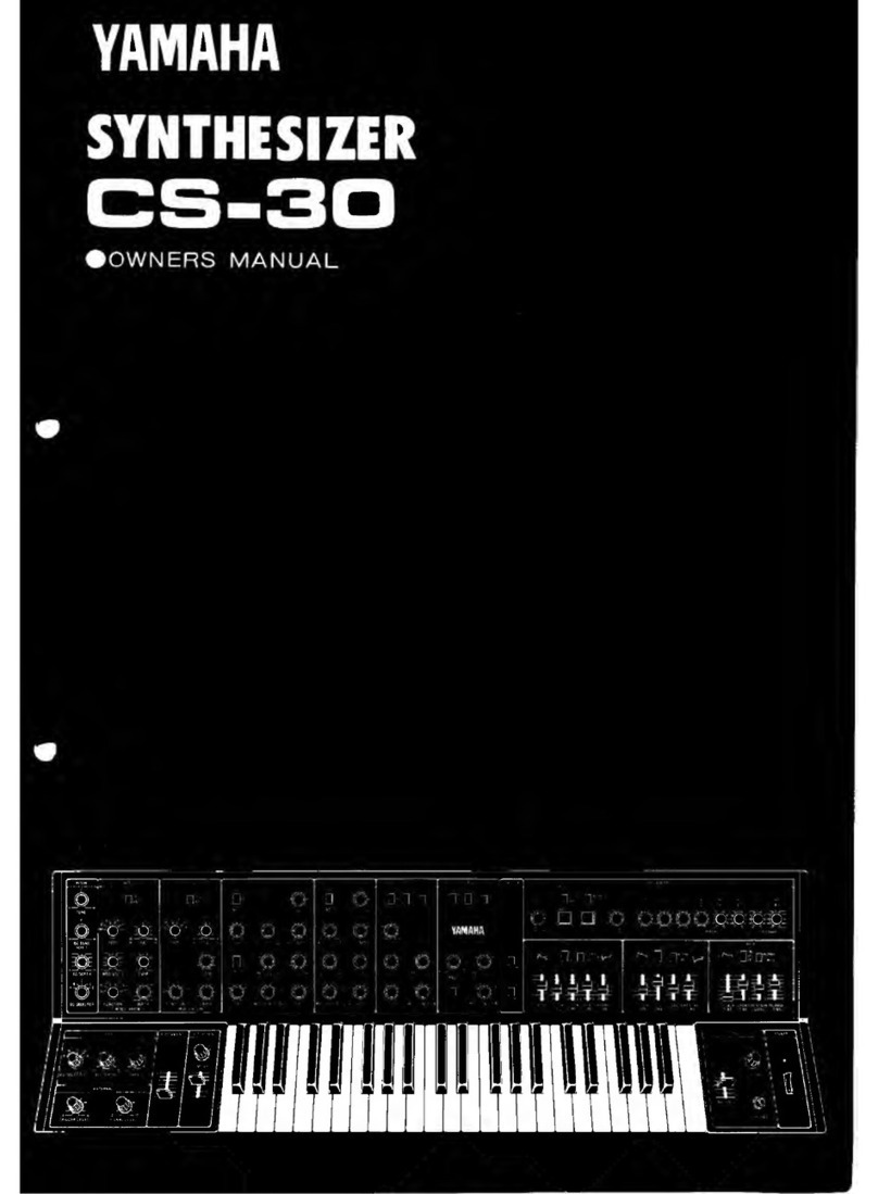
  9. Yamaha CS-30L User manual

Yamaha CS-30L User manual

Other manuals for CS-30L

2

Other Yamaha Synthesizer manuals

Yamaha TG-33 User manual

Yamaha

Yamaha TG-33 User manual

Yamaha YS100 User manual

Yamaha

Yamaha YS100 User manual

Yamaha P-120 P-120S User manual

Yamaha

Yamaha P-120 P-120S User manual

Yamaha P-150 User manual

Yamaha

Yamaha P-150 User manual

Yamaha DX7 II FD User manual

Yamaha

Yamaha DX7 II FD User manual

Yamaha TX816 Manual

Yamaha

Yamaha TX816 Manual

Yamaha FB-01/U User manual

Yamaha

Yamaha FB-01/U User manual

Yamaha CS01 User manual

Yamaha

Yamaha CS01 User manual

Yamaha SY-1 User manual

Yamaha

Yamaha SY-1 User manual

Yamaha P-120 User manual

Yamaha

Yamaha P-120 User manual

Yamaha SY.22 User manual

Yamaha

Yamaha SY.22 User manual

Yamaha CS-5 User manual

Yamaha

Yamaha CS-5 User manual

Yamaha PF-1000 User manual

Yamaha

Yamaha PF-1000 User manual

Yamaha PF-500 Installation and operation manual

Yamaha

Yamaha PF-500 Installation and operation manual

Yamaha FB-01 User manual

Yamaha

Yamaha FB-01 User manual

Yamaha pf10 User manual

Yamaha

Yamaha pf10 User manual

Yamaha CS-5 User manual

Yamaha

Yamaha CS-5 User manual

Yamaha PortaTone PSR-400 User manual

Yamaha

Yamaha PortaTone PSR-400 User manual

Yamaha S90 XS Editor VST S70 XS Editor VST User manual

Yamaha

Yamaha S90 XS Editor VST S70 XS Editor VST User manual

Yamaha Loopfactory AN200 User manual

Yamaha

Yamaha Loopfactory AN200 User manual

Yamaha CS-60 User manual

Yamaha

Yamaha CS-60 User manual

Yamaha SY55 User manual

Yamaha

Yamaha SY55 User manual

Yamaha SY-35 User manual

Yamaha

Yamaha SY-35 User manual

Yamaha DX5 Quick start guide

Yamaha

Yamaha DX5 Quick start guide

Popular Synthesizer manuals by other brands

NEON CAPTAIN Radioator user manual

NEON CAPTAIN

NEON CAPTAIN Radioator user manual

Roland JD-800 owner's manual

Roland

Roland JD-800 owner's manual

Joranalogue Contour 1 user manual

Joranalogue

Joranalogue Contour 1 user manual

Full Bucket Music Mono/Fury manual

Full Bucket Music

Full Bucket Music Mono/Fury manual

IK Multimedia UNO Synth PRO X user manual

IK Multimedia

IK Multimedia UNO Synth PRO X user manual

Kawai MP7 Software update

Kawai

Kawai MP7 Software update

Roland Gaia SH-01 Quick guidebook

Roland

Roland Gaia SH-01 Quick guidebook

Behringer DEEPMIND 12 quick start guide

Behringer

Behringer DEEPMIND 12 quick start guide

Roland GR-30 manual

Roland

Roland GR-30 manual

Moog Minitmoog 300A Owner's service manual

Moog

Moog Minitmoog 300A Owner's service manual

Gotharman Gotharman's anAmoNo-box user manual

Gotharman

Gotharman Gotharman's anAmoNo-box user manual

QuStream HDFS-550 Technical manual

QuStream

QuStream HDFS-550 Technical manual

Akai AX80 Operator's manual

Akai

Akai AX80 Operator's manual

Roland GS-500 instructions

Roland

Roland GS-500 instructions

Octave Cat SRM Service manual

Octave

Octave Cat SRM Service manual

Dreadbox Murmux Initiate manual

Dreadbox

Dreadbox Murmux Initiate manual

neutral labs ELMYRA 2 Build guide

neutral labs

neutral labs ELMYRA 2 Build guide

Waldorf KYRA user manual

Waldorf

Waldorf KYRA user manual

manuals.online logo
manuals.online logoBrands
  • About & Mission
  • Contact us
  • Privacy Policy
  • Terms and Conditions

Copyright 2025 Manuals.Online. All Rights Reserved.

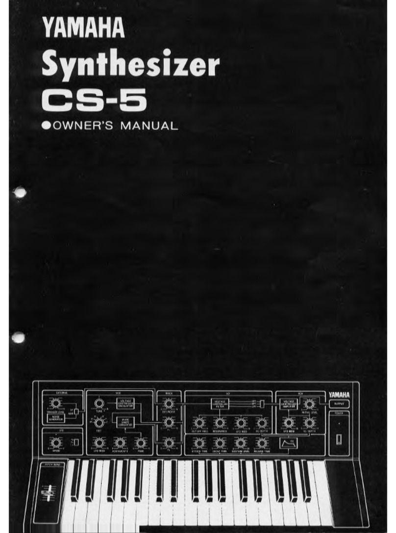
SYNTHESIZER CS-30L
We thank you very much for your purchase of our YAMAHA synthesizer CS-30L. The CS-30L is a
full-fledged synthesizer developed based on YAMAHA 's superior technology and rich experience cultivated
over the years with YAMAHA Electone Organs and by giving full play to the latest in IC technology.
The synthesizer, unlike other musical instruments, has no fixed sound of its own. However, it has the
capacity of producing, with practically unlimited freedom, new sounds that no other instruments can
produce. The new sounds that you have created yourself with the CS-30L, will no doubt direct you along
apath that will lead you into anew world of music.
The CS-30L is asynthesizer equipped with 2systems of VCO, VCF and VCA as well as 3Eds. Further,
it is provided on its rear panel with terminals that will enable its use also as aguitar synthesizer as well as
connection to 2, or more, other synthesizers. To make full use of such functions and to discover original
sounds that are uniquely yours, we urge you to read the contents of this Owner's Manual carefully.
Full attention should be paid to the following points
prior to operation.
•Place of installation
When installing the synthesizer, such places as those
subjected to direct sunshine, or dusty or highly
humid places should be avoided, Furthermore, in
no case should it be installed close to fire, or heat-
generating objects such as apower amplifier, as it
may not only cause disorders and cabinet deforma-
tion but may also lead to afire disaster.
•Cleaning
When cleaning the set, do not wipe the panel, or
keyboard with athinner-type liquid, or spray of the
same-type liquid; as it will cause discoloration, or
stains. Always wipe it with asoft and dry piece
of cloth,
•Connection
Connections such as to amplifiers should be carried
out properly with full care. Erroneous connections
will lead to disorders of the synthesizer and ampli-
fier.
•VOLUME
The application of an excessive input to the amplifier
may cause damage of the amplifier or speakers. For
this reason, careful consideration must be given when
setting the volume.
CONTENTS PAGE
CHARACTERISTIC POINTS OF
SYNTHESIZERS 4
CONNECTION 6
BASIC SETTING 7
FUNCTIONS OF EACH SECTION
KEYBOARD/PITCH 8
VC01/VC02 9
VCF1/VCF2 10
VCA1/VCA2 11
TRIGGER/EG 12
EG/EFFECT 13
LFO/EFFECT 14
EXTERNAL 15
OPERATION SEQUENCE 16
TROUBLE SHOOTING 19
SOUND MEMO 20
BLOCK DIAGRAM 21
SPECIFICATIONS 22
CHARACTERISTIC POINTS OF SYNTHESIZERS
The function of the synthesizer is to electrically
synthesize and control the three elements of sound,
that is, interval, tone and volume as well as the timewise
change from the instant asound is generated to the
point it fades away.
The interval is controlled by the VCO, tone by the
VCF, volume by the VCA and the timewise variation
of sound by the EG, "VC" in VCO, VCF and VCA
stands for "voltage-controlled". Now, let us consider
what kind of function this voltage control has in the
synthesizer. The drawing at the right is the block
diagram showing the basic composition of asynthesizer.
•KEYBOARD CIRCUIT
This circuit generates the key's voltage (KEY
VOLT) that corresponds to the interval, and the
signal voltage (TRIGGER) that indicates that the
key is being depressed. Although the TRIGGER will
become "o" volt when the finger is released from
the key, the KEY VOLT that indicates the interval
will be memorized by the SAMPLE AND HOLD
(S/II) circuit until the next key is depressed.
The drawing at the right shows the relationship
between the key's interval and KEY VOLT voltage
together with the wave forms of the TRIGGER and
KEY VOLT signals mi (E) do (C) -* sol (G)
are depressed.
•VCO (Voltage control oscillator)
The VCO makes asound source of afrequency
that corresponds to the KEY VOLT of the key-
board circuit. It oscillates simultaneously such sound
source wave forms as saw-tooth waves and square
waves that have agreat number of harmonics and
sine waves of asingle frequency. Although the
oscillator frequency corresponds linearly to the KEY
VOLT value, if the oscillator should be controlled
while adding an AC voltage such as low frequency
oscillator (LFO) to the KEY VOLT voltage, it will
be possible to modulate the key interval with the
LFO, or the like. The function of adding this voltage
is carried out by an adder. Regarding this voltage
value that is used to control the VCO, it is possible
to freely control the VCO's oscillating frequency
in accordance with the voltage value since asyn-
thetic voltage formed by several AC wave forms is
used instead of afixed DC voltage.
The drawing at the right shows acase of VCO
control in which the sine waves of the LFO is
added to the KEY VOLT. Needless to say, it is
also possible to add an EG voltage in place of, or
simultaneously with, the LFO.
•VCF (Voltage controlled filter)
The VCF, which is the heart of the synthesizer,
VCO VCF VCA
KEYBOARD FOLLOW
EG
KEY VOLT
KEYBOARD
EG
TRIGGER
VOLTAGE KEY VOLT
C
PITCH
HOLD HOLD
mm TRIGGER
E| I[c
EG C
132
^KEYON
L-KEY OFF
-KEYON LKEY OFF
PITCH
VCO MOD
CONTROL VOLT
LFO
KEY VOLT
VCO OUT
creates the tone by changing the harmonic structure
by cutting, or emphasizing, with the filter apart of
the harmonics of VCO-produced sound source having
alarge number of harmonics.
The VCF creates the tone by changing the cut-
off frequency (existing on the borderline between
the passage and shield-off sections) by controlling
the voltage. To eliminate any harmonics structure
deviation fKEY BOARD FOLLOW) caused by the
difference in intervals, it is designed so that the
cut-off frequency will shift along with the shift in
the interval, by adding the KEY VOLT voltage of
the keyboard circuit to the DC voltage generated
with the use of the control. The tone can be rendered
with atimewise variation by adding to these con-
trol voltages avoltage such as that of the LFO, or
EG, that changes with time as in the case of the
VCO.
The drawing at the right illustrates the mode in
which the cut-off frequency of the LPF is controlled
by the EG.
VCA (Voltage controlled amplifier)
The VCA is an amplifier block whose amplifica-
tion degree is varied by the control voltage.
The drawing at the right shows acase in which
the amplification degree of the amplifier is controlled
by the EG voltage to give atimewise variation
(envelope) to the volume, from the point the sound
starts up to the point it fades away. Naturally, as
in the cases of the VCO and VCF, it is possible
to add avoltage such as of the LFO to the EG
voltage and use the resulting voltage as VGA's con-
trol voltage.
CUT OFF FRO.
-KEY VOLT
AMPLITUDE
INPUT OUTPUT
EG (Envelope Generator)
The EG has the function of producing the voltage
curve that indicates the condition in which the
sound changes in order to render the sound with a
timewise variation. Given asignal to initiate the
start and end of the envelope by the TRIGGER
voltage of the keyboard circuit, the EG generates
signals that will be used as the control signals for
the VCO, VCF, VCA, etc.
In addition to the elements described above, the
synthesizer has such elements as the LFO (low
frequency oscillator) that functions to give aperi-
odical variation, and controls to enhance the effects
of the performance. But in any case, the fact re-
mains the same that something is controlled by
changing the voltage.
In this way, since all controls in asynthesizer are
effected by using the voltage value as a medium,
the synthesizer is capable of producing various
variations of sounds with ease.
EG 1,1
TRIGGER
KEY-ON KEY-OFF ON OFF ON
Difference in envelope waveforms caused by
trigger waveforms.
CONNECTION
(T) POWER CORD
Connect the power cord plug into an AC outlet.
(2) OUTPUT
These are output terminals. They are terminals
for three different outputs: "1" and "2" will feed out
outputs respectively of VCA-1 and VCA-2, while "1 +
2" will feed out an output wherein VCA-1 and VCA-2
are mixed.
•Switchover can be effected among the voltage levels
to be fed out.
•The amplifier to be connected to the synthesizer
should have as flat as possible frequency response.
(3) FOOT SWITCH
SUSTAIN/PORTAMENTO
By connecting the FOOT switch, the effects of
the SUSTAIN and PORTAMENTO levers can be can-
celled.
@FOOT CONTROLLER
BRILLIANCE/VOLUME
By the use of the FOOT CONTROLLER, the
BRILLIANCE and VOLUME levers can be operated.
©KEY VOLT &(6) TRIGGER
By connecting the set with another synthesizer
having KEY VOLT and TRIGGER terminals, this
set can be used as amultiple-system synthesizer.
See Page 15 for further details.
®EXTERNAL
By connecting an electric guitar, or an electric
piano to this terminal, asynthesizer effect can be
given to the sound source. For further details, please
refer to Page 15.
•Connections should be carried out carefully as an
erroneous connection will become the cause of
troubles of the synthesizer and amplifier.
•Never apply an excessive input (5V, or more) to
the KEY VOLT's IN terminal as it will cause trouble
to generate in the synthesizer.
BASIC SETTING
The functions of the respective controls and switches will be described in the section starting
from Page 8. Here we shall merely refer to how basic setting is carried out when sounds are to be
produced experimentally to check the synthesizer, or amplifier.
This is for the case in which the saw-tooth waves (|\ )of VCO-1 are fed out from OUTPUT 1
and the square waves (V\_) of VCO-2 from OUTPUT 2in their original form. OUTPUT 1+2 will feed
out awaveform wherein the two are mixed.
—12 >H A7*3
n"43j! tuts,; ssa- Q;h^< .v
VV^10 ^6
D16 15 H8=^4
i
•*
ii'"V i.i ~13 'A iii•s* * S»'•i,
18 16 g.5II;1IM| IMr"
91
•Setting is carried out by checking the controls and
switches from 1to 18.
•Once the controls and switches are set in the state
of basic setting, sounds will be produced no matter
how other controls and switches may be set. How-
ever, to acquire abetter understanding of the func-
tions of each section, we suggest that you set them
as shown in the diagram.
•When sounds cannot be produced for some un-
known reason, the setting should be brought back
to the basic setting.
LEVEL
OUTPUT
1
LFO IN EG IN
EG OUT—
A*BfCf D* Ef
EG-1 EG-2
mm <Sa# mm fcb-3
functions KEYBOARD/PITCH
ill !Mil
Hf§
iqam
illllL
(2) (3) (4)
POWE R
©POWER
This is the power switch. When switched
the POWER indicator will illuminate.
ON,
OUTPUT
(2) VOLUME
These controls are used to control the overall
volume of CS-30L. The control on the amplifier
side should be fixed to an optimum position.
(3) BALANCE
Used to control the volume balance between
VCA-1 and VCA-2 in the CS-30L which has 2systems
of the VCO, VCF and VCA.
KEYBOARD
The CS-30 is amonotone synthesizer that covers
3-1/2 octaves with its 44 keys. When 2, or more,
keys are depressed simultaneously, priority will be
given to the key of the higher, or highest interval.
(Priority to higher sound)
®PHONES
This is an output terminal for the headphones.
PITCH
©TUNE
Used for adjusting the intervals. VCO-1 and VCO-
2will change in the same manner.
•It takes roughly 30 minutes for the stabilizer's inter-
vals to stabilize. Accordingly, when tuning is to be
carried out, power should be switched on approxi-
mately 30 minutes prior to tuning.
(DDE TUNE
Used for adjusting the intervals of VCO-1 alone.
The interval of VCO-2 will remain unchanged.
©-
(g>—
(3)(4>
(3)EG SELECTOR
Effects switchover of envelope generator (EG).
(4) EG DEPTH
Used when modulating the VCO with the envelope
generator: adjusts the depth.
w1
--J -__H
FUNCTIONS VC01 /VC0 2
©-
(6>
(5}
(4> 3©e o
:Jl=- —_JK
©FEET
As stated earlier, the keyboard covers 3-1/2
octaves with its 44 keys. By making use of this
FEET Switch, the sound range to be covered can
be shifted as shown in the diagram.
•VC01: Covers 2' ~64'
•VC02: Covers 4' ~128'
©PWAdjusts the pulse width of the square wave out-
put of VCO. (50% ~90%)
(3)PWM
Changes the pulse width at intervals equivalent
to LFO's period. (10%~90%)
(4) MODULATION FUNCTION
Used for switching over the way in which VCO
modulation is to be applied.
•At S/H, sounds whose intervals vary in an irregular
manner will be fed out.
•At EXT, the intervals will be varied by the external
input.
©MODULATION DEPTH
Modulates the VCO using the period of LFO.
PW: Pulse Width (at maximum change)
-5095- -90%—
Pulse Width: 90%
PWM: Pulse Width Modulator
"2596 7596
It changes in the order of
®-©-©-©-®.
U-O'
©MOD VC0Z
VCOl will be modulated by the output of VC02.
FUNCTIONS VCF1 /VCF2
(1) ©
3QE ©
(4) (I) © ©
LEVEL KBD F0L10W RESONANCF
MOD DEPTH EG DEPTH
-0 'O
'
LEVEL MOD FUNCTION EG SEtBCTOFi
O3&
FOLLOW SESONANCE
MOD DEPTH El
£
10D FUNCTION EG SEIECTOP
(8) C7)
ffiOARD r
EG IN
VCD
LFO IN
LFO IN
IINPUT LEVEL
)... -.[Sl+Sjf
._>-<_
VLEVEL
WI
>;<-»l—I•
VCF-1 -
LFO IN EG IN
Li
INPUT
VCF IHP
—-*r
4-^
!!
S i
I1
•
VCF-2 -
IT
LFO IN EG II
n+2
LFO iN EG IN
©INPUT/LEVEL
These are input changeover switches and acon-
trol for the VCF.
•No control is provided for the VCF-2 side.
©CUT OFF FRQ
Adjusts the cut off frequency of the VCF.
(3) RESONANCE
Adjusts the resonance in the neighborhood of
the VCF cut off frequency.
(4) KBD FOLLOW
It is designed so that the cut off frequency of
the VCF will shift, following the intervals of the
keys. This is the control used for adjusting the
following properties.
(5) MOD FUNCTION
Selects waveform of LFO with which VCF is to be
modulated.
•At S/H, sounds whose tones vary in an irregular man-
ner will be fed out.
•At EXT, the tones will be modulated by the external
input.
(6) MOD DEPTH
Adjusts modulation degree.
EG SELECTOR
Selects envelope generator.
®EG DEPTH
Adjusts the way in which EG is to be applied.