Yamatake HTY79 User manual

AB-5963
1
Insertion Dewpoint
Temperature / Humidity Sensor
HTY79X3 / HY79X3
General
Insertion dewpoint temperature / humidity sensor
HTY79X3 series uses a Pt100 platinum film temperature
sensing element and a polymer capacitive film humidity
sensing element (FP3 specially developed by Yamatake)
which ensures highly accurate and reliable tempera-
ture/humidity sensing. It is designed to be installed in
return air ducts of commercial buildings, in return air
chambers of air handling units or in ventilated shield for
meteorological instruments. HY79X3 series for sensing
only dewpoint temperature without separate temperature
sensor is also available.
Features
1)Wide sensing range
2)Excellent long term stability
3)Highly resistant to environment
4)Quick response and high repeatability.
5)Easy to install in a duct (bracket prepared)
6)Splash-proof housing (IP54)
Models
Model No. Shape Type Power
supply Humidity
output Temperature
output Fixed Fixed Description
HTY79 Insertion dewpoint temperature sensor (w/separate
temperature sensor)
HY79 Insertion dewpoint temperature sensor
0 Insertion length: Long
1 Insertion length: Short
3―
T Shared 24 V DC, 24 V AC
1 Humidity output 1-5 V
4 Humidity output 4-20 mA
6 Humidity output 0-10 V
0 W/o temperature sensor
P Temperature Pt 100
00―
Specifications/Instructions
▲HTY7903
▲HTY7913

2 AB-5963
Select a model No. from below
HTY7903T1P00 Dewpoint (1-5 V) + temperature (Pt 100) Insertion length: Long
HTY7903T4P00 Dewpoint (4-20 mA) + temperature (Pt 100) Insertion length: Long
HTY7903T6P00 Dewpoint (0-10 V) + temperature (Pt 100) Insertion length: Long
HTY7913T1P00 Dewpoint (1-5 V) + temperature (Pt 100) Insertion length: Short
HTY7913T4P00 Dewpoint (4-20 mA) + temperature (Pt 100) Insertion length: Short
HTY7913T6P00 Dewpoint (0-10 V) + temperature (Pt 100) Insertion length: Short
HY7903T1000 Dewpoint (1-5 V) Insertion length: Long
HY7903T4000 Dewpoint (4-20 mA) Insertion length: Long
HY7903T6000 Dewpoint (0-10 V) Insertion length: Long
HY7913T1000 Dewpoint (1-5 V) Insertion length: Short
HY7913T4000 Dewpoint (4-20 mA) Insertion length: Short
HY7913T6000 Dewpoint (0-10 V) Insertion length: Short
Safety Instructions
Please read instructions carefully and use the product properly. Please keep this instruction on hand for reference at
any time.
Usage Restrictions
This product is targeted for general air conditioning. Do not use this product in a situation where human life may be
affected. If this product is used in clean rooms or places where reliability or control accuracy is particularly required,
please contact Yamatake’s sales representatives. Yamatake Building Systems Co., Ltd. bears no responsibility for
any benefit, or lack of benefit, derived from the operation by the customer.
CAUTION
●Installer must be a trained, experienced service technician.
●Check the ratings given in this instructions to prevent equipment damage.
●Check the environment given in this instructions to prevent equipment damage.
●Disconnect power supply before wiring to prevent electric shock or equipment damage.
●All wiring must comply with local codes and ordinances.
●Use crimp contacts with insulation jackets for wire terminals.
●Do not remove or disassemble casing except for wiring. May result in equipment damage.
●When the product is faulty, the reduced output may result in excessively humid status. Take safety
measures at controller.

3 AB-5963
Specifications
Item Specifications
Temp. –20 to 60 °CMeasurement range Dewpoint –40 to 60 °C DP (–20 to 60 °C)
Temp. 100 Ω/ 0 °COuput signal Dewpoint 1-5 V DC (linear to –40 to 60 °C DP) (output impedance: min. 10 kΩ)
0-10 V DC (linear to –40 to 60 °C DP) (output impedance: min. 10 kΩ)
4-20 mA DC (linear to –40 to 60 °C DP) (maximum permmisible load 300 Ω)
Temp. +/– 0.3 °C (at condtions of –20 to 60 °C)Sensing accuracy Dewpoint +/– 1 °C DP (at condtions of 30 to 90 % RH 25 °C)
+/– 2.5 °C DP (at condtionas of 30 to 90 % RH –5 to 55 °C)
Temp. Max. 4 min.Time constant
(at air velocity 2 m/s) Dewpoint Max. 1 min. (when humidity is constant)
Temp. Rated operaing condtions: –20 to 60 °C 0 to 100 % RH (non-condensing)
Extreme oprating condtions: –20 to 60 °C 0 to 100 % RH (non-condensing)
Storage condtions: –30 to 70 °C 5 to 95 % RH (non-condensing)
Humid. Rated operaing condtions: –5 to 55 °C 10 to 100 % RH (non-condensing)
Extreme oprating condtions: –20 to 60 °C 0 to 100 % RH (non-condensing)
Storage condtions: –30 to 70 °C 5 to 95 % RH (non-condensing)
Environmental conditions
Air velocity Extreme oprating condtions : 0 to 15 m / s
Power supply 24 V AC +10 / –15 % (50/60 Hz), 24 V DC +/– 10 % (only for HTY、HYseries)
Power consumption 0.6 VA (at conditions of 24 V AC, HTY, HY series 1-5 V, 0-10 V output model)
450 mW (at conditions of 24 V DC, HTY, HY series 1-5 V, 0-10 V output model)
1.4 VA (at conditions of 24 V AC, HTY, HY series 4-20 mA output model)
1.2 W (at conditions of 24 V DC, HTY, HY series 4-20 mA output model)
Dielectric strength 500 VAC less than 1 mA of leak for 1 minute
Insulation resistance 500 VDC min. 20 MΩ
Vibration resistance 9.8 m/s² (10 to 150 Hz)
Protection Housing IP54 (when splash-proof connectors and disgnated multi-core calbes are used or when a designated
conduit is used)
Insatllation Duct, air chamber, ventilated case for meteological instruments (with special bracket)
Wiring Terminal block connection
Material Housing: GF20 % Polycarbonate mixed resin, gray (equivalent to DIC-651)
Filter cap: denatured PPE resin, gray (equivalent to DIC-651)
Weight Approx. 240 g (7903 series) Approx. 210 g (7913 series)
Accessories None
Order separatly 83157235-001 Mounting bracket
83157240-004 Conduit mounting set (for HTY, HY series、applicable cable outer diameter11 to 14 φ)
83104098-004 Seal connector (for HTY, HY series、applicable cable outer diameter 10.5 to 14.5 φ)
DY8000A1001 Sensor shield for outdoor
DY3002A1005 ventilated case mounting bracket (L shape metal)
Order separately for
maintenance 83162945-003 Filter set

4 AB-5963
Dimensions (mm)
(1) 7903 series
(2) 7913 series
(3) Mounting bracket
62.5
25 50 60
40
6072.3
φ30
3.3
247.6 51.3
45.6 67.3
A
70
φ20
110
1135
A
108.6 51.3
45.6 67.3
70
φ20
110
1135

5 AB-5963
Installation
Important
1)Select a location where the typical temperature and
humidity of the measured fluid can be sensed and
where the wind speed requirements are met.
2)Make sure that the temperature and humidity elements
are entirely immersed in the measured fluid. Also,
make sure that air can pass over the side of the sensor.
3)Allow adequate service clearance at the front of the
cover.
4)When installing in steam heating air handling unit,
make sure the steam does not directly expose. (It
may exceed the extreme operating condition
5)When inserting the insertion part facing upward,
prevent dew condesation. (The condensated dew will
remain in the fileter cap and measurement difference
will occur until it becomes dried.)
CAUTION
Do not step on the unit.
Mounting 7903 series (duct mounted)
1)Prepare the mounting bracket in advance.
Attach the mounting label at the sensor mounting
position and make a hole in the duct at the point
indicated on the label. Fix the mounting bracket onto
the duct with M4 screws, inserting packing between the
duct and the bracket.
Cover the duct with an insulating material. (If you cover
the duct with an insulating material first, fill the
clearance between the bracket and the duct with the
insulating material after fixing the bracket.)
2)Turn the stopper of the main unit to the left and insert
the main unit into the bracket, aligning the claw to the
bracket groove. Fix it by turning the stopper 45 ° in
the clockwise direction.
Mounting 7913 series (air handling unit
mounted)
1)Prepare the mounting bracket in advance. Attach a
mounting label at the desired mounting position and
make a hole in the air handling unit return air chamber.
Fix the mounting bracket onto the duct with M4 screws
(included) between the duct and the bracket.
2)Turn the stopper of the main unit to the left and insert
the main unit into the bracket, aligning the claw to the
bracket groove. Fix it by turning the stopper 45 °
clockwise.
Duct
Air flow
Duct
Packing
A
ir flow
Insulating material
Panel
Panel
Air flow
Claw
Stopper
45° (2)
(1)
45° (2)
(1)
Claw
Stopper

6 AB-5963
Wiring (common instructions for 7903 series
and 7913 series)
1)Dismount the cover.
(i) Cable connection
Prepare the proper seal connector (order separately) in
advance, if required.
Screw the threaded seal connector into the main and
lead the cable through it.
(ii) Conduit connection
According to the number of cable cores, prepare a
conduit set (order separately) in advance. Fix the
conduit connector and the attachment tentatively with a
screw. Select an O-ring ideal for the cable.
Lead the cable, as shown in the following diagram.
Pull up the cable and fix the attachment to the main unit
with a screw.
Tighten the nut on the conduit at a point where the
conduit lock screw can be tightened easily.
2)Connect the wires to the terminals and close the cover.
Tighten the seal connector. (only when cable
connected)
Terminal Nos. and cable cores
Seal connector
(order separately)
Nut attached to
conduit
Attachment
Conduit connector
(nominal size: 25 mm)
Pull the cable
Tightening direction
Nut attached to conduit
Conduit connector
(nominal size: 25 mm)
Straight box connector
(nominal size: 24-25 mm)
Conduit lock
screw
Attachment
O-ring
Tighten
Allow sufficient
service clearance
~(+)
Pt 100
1
2
3
4
5
6
7
A
B
B
24 V AC
(24 V DC)
1-5 V DC
0-10 V DC
4-20 mA
HTY7903T1P00
HTY7903T4P00
HTY7903T6P00
HTY7913T1P00
HTY7913T4P00
HTY7913T6P00
(Cable cores:7)
⊥(–)
+
–
HY7903T1000
HY7903T4000
HY7903T6000
HY7913T1000
HY7913T4000
HY7913T6000
(Cable cores:4)
Power
supply
Dewpoint
Tempe
rature

7 AB-5963
Wiring Instructions
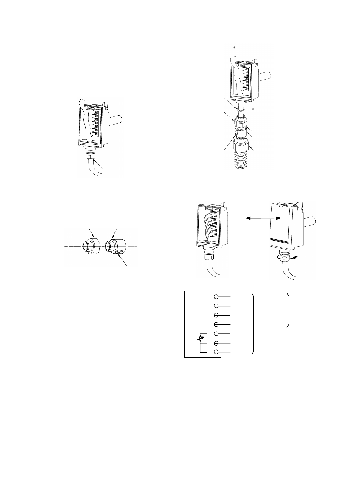
Shielded multi-core cables (CVV-S) of 1.25 mm² or 2
mm² are recommended. Be sure to ground the shielded
cable on the controller side.
If you don't need splashproof, a 1.25 mm² or 2 mm² IV
cable may be used for power and a 1.25 mm² shielded
cable for humidity and temperature signals.
The maximum cable length is 100 m.
Never connect power supply to temperature output.
Always check wiring before supplying power.
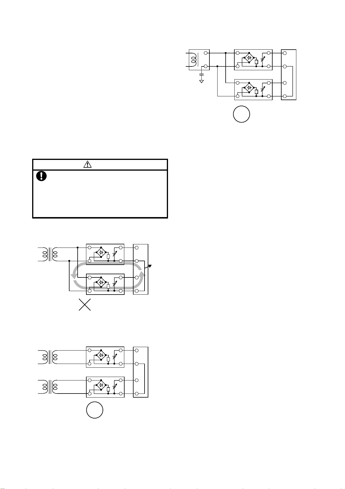
Never share 24V AC transformer to other products.
Use of individual AC transformer of humidity
transimitter
CAUTION
Use insulated transformer to supply 24 V AC
power supply voltage.
Never share 24 V AC power supply with other
equipment.
If a transformer is shared with other equipment,
loop will be formed at common and the
sensor/transmitter may be damaged.
•Transformer (24 V AC power supply) shared
•Transformer (24 V AC) separated
•24 V DC power shared
Follow the next instructions to prevent an induction cur-
rent flowing from the humidity sensor to the controller
input circuit, or to prevent an influence on the generating
noise due to inadequate time constant of the controller
input.
•Use a controller with a low pass filter with a removal
ratio of 40 dB or higher (normal mode).
•Connect an isolator to the controller input circuit if a
removal ratio is unknown.
•If you use a Yamatake cotnroller, no problem will
occur.
Maintenance
Since the temperature / humidity sensor have been in-
spected and adjusted accurately before shipment, they
need no adjustment at the site. However, follow the
maintenance instructions below :
1)Periodical inspection
Determine the periodical inspection intervals according
to the amount of suspended dust and other
contaminants in the environment. Regulary check the
sensor’s accuracy and the condition of its cover.
2)Troubleshooting
If any problem occurs during operation, refer to the
following table for appropriate solutions.
No common loop formed
Common loop formed, however, not so
affected by common mode noise.
Good
24 V DC
+
++
+
⊥
⊥⊥
⊥
+
++
+
-
--
-
+
++
+
-
--
-
+
++
+
-
--
-
~
~~
~
⊥
⊥⊥
⊥
~
~~
~
+
++
+
-
--
-
-
--
-
Temperature / humidity sensor
Common loop formed
Not Good
24 V AC
Multi-loop
controller
Common
share
+
++
+
⊥
⊥⊥
⊥
+
++
+
-
--
-
+
++
+
-
--
-
-
--
-
~
~~
~
⊥
⊥⊥
⊥
Temperature / humidity sensor
~
~~
~
-
--
-
+
++
+
Good
24 V AC
+
++
+
+
++
+
-
--
-
+
++
+
-
--
-
+
++
+
-
--
-
~
~~
~
⊥
⊥⊥
⊥
24 V AC ~
~~
~
⊥
⊥⊥
⊥ -
--
-
Multi-loop
controller
Temperature / humidity sensor
Multi-loop
controller
Temperature / humidity sensor

8 AB-5963
Troubleshooting
Problem… Check… Action…
- No output
generated
- Unstable output
- Check loose
connection
- Check Incorrect
wiring
- Check supply voltage
- Check sensor
damage
- Tighten the terminal
brock
- Re-wire
- Replace sensor
- Slow response
- Error in output
- Check the sensor for
water leakage or
condensation
- Check the installed
location
- Check the dust, soil.
- Removetheunit from
bracket.
Dry the unit with no
power.
- Refer tothe
Installation
instructions
- Clean filter
- Replace filter
- Humidity one point
adjustment
- Replace the product
3) Replacing the filter:
(1) Prepare filter set (order separately) in advance.
Remove the filter cap and filter by hand.
(2) Cover the sensor with the new filter and then put
the new filter cap over.
(3) Tighten the filter cap.
4) Humidity one point adjustment
When you find a calibration error in the humidity sen-
sor, re-calibrate the sensor using the adjustment vol-
ume (VR1, VR2) located on the circuit board. The out-
put value is increased by turning this volume in clock-
wise direction and decreased by turning it counter-
clockwise. Use refelenced humidity meter of ade-
quate accuracy. A digital multimeter is recommend-
ed to check the output voltage.
Parts Identification of adjustment volume
Cautions
1. After unpacking, age the transmitter in the ambient
atmosphere for at last 24 hours.
2. To calibrate and adjust, take care the heat from human
body or appliances.
3. When one-point adjustment is done at an environment
where relative humidity is higher than 50 % RH, the
dewpoint temperature accuracy specifications may not
be met to where relative humidity is under 50 % RH.
Yamatake Building Systems Co., Ltd.
Yamatake Corporation
International Business Division
Totate International Bldg.
2-12-19, Shibuya, Shibuya-Ku
Tokyo, 150-8316, Japan
Phone: 81-3-3486-2350
Facsimile: 81-3-3486-2592
Rev. 1.0 Dec. 2000 Printed in Japan. AB-5963 0.5H-H (W)
Specifications are subjects to change without notice.
①
②
Filter cap (The cap will remove
with the filter inside.)
Loosen
Filter cap
Filter
Filter cap
Tighten
Rough adjustment knob (VR2)
Fine adjustment knob (VR1)
This manual suits for next models
1
Table of contents
Other Yamatake Accessories manuals
Popular Accessories manuals by other brands

eXempt
eXempt C3 Pro user manual

Vega
Vega PROTRAC Series operating instructions

Thermo Electron
Thermo Electron 3950 Operating and maintenance manual

Dorner
Dorner AquaPruf 7400 Ultimate CE Series Installation, Maintenance, and Parts Manual

Guzzanti
Guzzanti GZ-40R instruction manual

Bosch
Bosch ISW-EN1247 installation guide