Yamato WA Series User manual

AUTO PURE WATER PURIFIER
WA / WC / WB / WG SERIES
MODEL
WA301/311 Series
WC301/311 Series
WB301/311 Series
WG301/311 Series
INSTRUCTION MANUAL
- FIRST EDITION –
•Thank you for purchasing WA / WC / WB / WG Series Auto Pure
Water Purifier of Yamato Scientific.
•To use this unit properly, read this "Instruction Manual" thoroughly
before using this unit. Keep this instruction manual around this unit
for referencing at any time.
WARNING: Carefully read and thoroughly understand the important
warning items described in this manual before using this unit.
Yamato Scientific America Inc.
Santa Clara, CA

CONTENTS
♦HEALTH AND SAFETY……………………………………………………………......
1
♦SYSTEM OVERVIEW ……………………………………………………...…….…….
2
●FLOW DIAGRAM ……………………...……………………………………........
2
♦MODEL TYPES ……………...…………………………………………………………
3
♦MODEL CONFIGURATION ……………………………………………...……………
4
●MODEL & VOLTAGE OPTIONS………...……………………………….............. 4
♦INSTALLATION ……………………....……………………………………………......
5
♦SYSTEM CHECKLIST …………………………...…...………………………............
6
♦INSTALLATION ……………………...…...………………………….………………...
8
● SYSTEM WALL MOUNT INSTRUCTION ….……………………………………........ 8
● REMOTE CONFIGURATION INSTRUCTION ………………………………….......... 9
● ELECTRICAL CONNECTIONS…....……….…………………………….................... 10
♦FACTORY INSTALLED OPTIONS….…………………………….………………….
11
♦HOME SCREEN OVERVIEW...……………………………………………………….
14
♦SYSTEM HARDWARE OVERVIEW………………………………………………….
15
● START UP CONSUMABLES…………………………………………………............
15
♦COMMISSIONING & START UP……………………………….…………….……...
16
♦OPERATION PROCEDURES…………………………………………………………
18
● INITIALIZING THE SYSTEM FOR THE FIRST TIME………………………………
18
● NORMAL OPERATIONS………………………………………………………………
21
● DISPENSING OPERATIONS………………………………………………..............
23
♦MAIN MENU – SERVICE CONFIGURATION………………………………….……
26
♦CONFIGURATION MENU………………………………………….………………….
27
♦SYSTEM AND INFORMATION & EVENT LOGS………………….………………..
29
♦MAINTENANCE………………………………………………………………………...
30
♦HEALTH STATUS………………………………………………….…………………...
31
♦CONSUMABLE REPLACEMENT……………………………….……………………
33
♦FILTER DETECTION AND LEAK DETECTION ERRORS………………...………
35
♦SANITIZATION …………………………………………………………………………
36
♦TROUBLESHOOTING ………………………………….…………………………......
41
♦SYSTEM & CONSUMABLES………………………………………...….……………
44
♦SPARE PART DETAILS & DIAGRAM…….……………………….…………...…...
46
♦DIMENSIONAL DRAWINGS…………………………………………….…………….
47
♦PRE-INSTALLATION CHECKLIST……………………………………….………….
49
♦AFTER SERVICE & WARRANTY ………………...…………………………………
50
You have a quality, world class water treatment system that will provide ultrapure water
for many years of trouble-free operation. Years of engineering and experience went into
the design and manufacture of this instrument which will dispense water exceeding Type
I water purity standards.

Installation and service of the equipment should be performed by authorized and trained
personnel. Safety measures and local guidelines must be followed. Use good practices
wearing personal protective equipment (PPE) during the installation and service of the
equipment.
Electricity – Auto Pure lab water equipment should be powered by a grounded GFI electrical
connection. Do not open the system unless the system is unplugged. Before any installation
or service is performed on the equipment, make sure the power is isolated. To unplug the
system, do not pull directly on the cord but grip the plug and remove it from
the outlet.
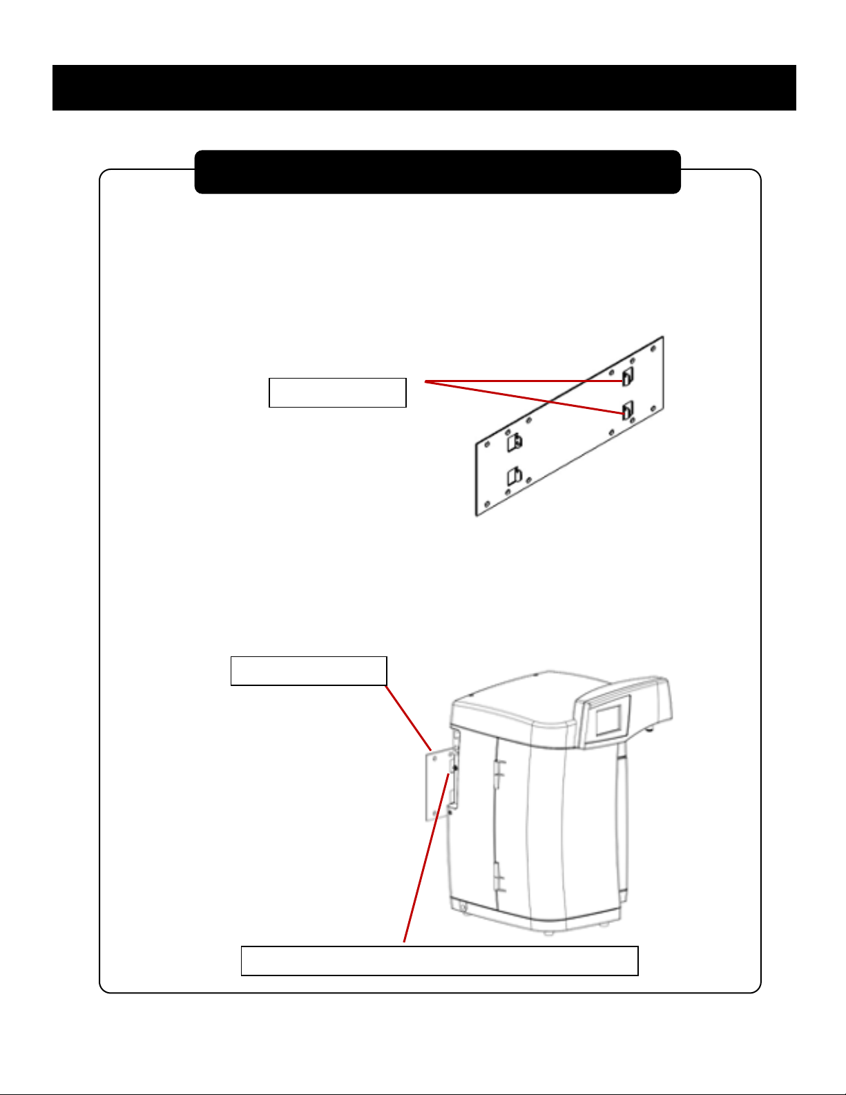
Ultraviolet Light – Auto Pure lab water systems may include an ultraviolet light lamp in a
stainless-steel housing. Make sure all power is removed prior to accessing the side panel to
perform any UV maintenance. Make sure gloves are used when handling the UV bulb.
(Gloves must be worn when handling the UV bulb. Which protects the integrity of the bulb)
Do not look directly at the UV lamp while the system is operating.
Water Supply – Good piping practices should be followed feeding water to the lab equipment.
Isolation valves, pressure gauges and bleed valves are recommended on the main water
supply. Pressure should be regulated to meet the minimum and maximum specifications
stated for the equipment.
Sanitization – Make sure PPE is worn during any sanitization process. The Phoenix system
uses chlorine dioxide gas as a disinfectant. Gas is generated within the system, but the
chlorine dioxide gas will be discharged during sampling and flushing sequences. Chlorine
dioxide gas is a respiratory irritant. Avoid breathing fumes and ensure the area is sufficiently
ventilated.
1
HEALTH AND SAFETY

The Auto Pure Lab water system delivers Type 1, 18 MΩ quality water on demand. Water is
purified in a staged process consisting of high-purity ion exchange resins to remove dissolved
minerals and internal recirculation to maintain purity. At discharge, a final 0.2µm filter removes
particulates and bacteria to attain CLSI / ASTM Type 1 water specifications. Additional optional
technologies are incorporated depending on model. Resistivity monitor provides feedback of the
final water quality.
The Auto Pure system is designed to recirculate through multiple technologies to maintain purity.
At designated periods, the system will transition from “Polishing” mode to “Stand By” mode and
the recirculation pump, solenoid, and UV (if installed) will be automatically turned off via the PLC
Controller. The main screen provides resistivity, TOC (if installed) and the life of the consumables.
The status bars will transition from green, to yellow and to red. The user will still be able to operate
the unit during all of these conditions. The unit comes with a built in Leak Detector and when
alarmed, it will automatically shut down the system. Alarms and service events are conveniently
logged. The unit comes with volumetric dispensing and provides the user six different batch sizes.
The user can enter in a numeric value, in mL units, for repeated dispensing. A button is pressed
and it will stop automatically once the limit has been reached.
2
SYSTEM OVERVIEW
FLOW DIAGRAM

\
3
MODEL TYPES

Countertop Remote Configuration
ARI-PHADG - Dispensing Gun with 0.2 micron Final Filter – Factory Installed option.
Recirculating gun mounted on the side of the unit with approximately 5 feet of span.
User manually dispenses water. Option not available with remote configuration
ARI-PHADF - Direct Feed – Factory installed option. Secondary Port on the side of the
system. Used to feed ancillary equipment such as analyzers and scientific equipment.
Internal pressure switch automatically keeps the system operating during a water draw
condition. Note, there is no final filter on this port. A downstream final filter may be
considered.
ARI-PHAWB - Wall Mounting Bracket – Factory Installed option. Wall mounting bracket
supplied with additional support base plate to the main system.
110 VAC / 60 Hz
220 VAC / 50 Hz
4
MODEL CONFIGURATION
MODEL OPTIONS
VOLTAGE OPTIONS

It is recommended to review the pre-site requirements before proceeding with the installation.
Read through the entire manual prior to the start of the installation. Read through the entire
manual prior to the start of the installation. Review all paperwork of items that have been ordered
and compare to the items that have shipped. If any parts are missing, notify the factory or your
sales contact.
CONNECTIONS
- Inlet - 3/8” Quick Disconnect Inlet
- Outlet – ¼ FNPT
- Direct Feed Port – 3/8” CPC Female Bulkhead with CPC Male x 3/8” OD Tube Compression
POWER REQUIREMENTS
- 110 VAC 60 Hz (1.0 amp), 220 VAC / 50 Hz (0.5 amp)
- Dedicated GFCI protected outlet six feet within the system
FEED WATER PRESSURE
20 – 90 PSIG regulated. If gravity feed water is used, an external delivery pump with auto shut
off will be required (Part number: ARI-1200109)
PARAMETER REQUIREMENT
Source/Type
Reverse osmosis (RO) or Service deionization (SDI)
preferred. 0.2μm particulate prefiltering is recommended
for SDI and tap water feeds
Conductivity RO: < 20μS/cm
SDI: > 1 MΩ (Resistivity)
TOC
(Using appropriate conditioning
as necessary)
RO: < 50 ppb
SDI: < 200 ppb
Temperature 20° F to 100°F (5° C to 38°C)
Pressure 20 PSIG minimum / 90 PSIG maximum
(1.38 to 6.21 bar)
Fouling Index Silt Density Index: < 3
Dissolved Carbon Dioxide < 30 ppm
Free Chlorine < .05 ppm
5
INSTALLATION REQUIREMENTS
INFLUENT WATER SPECIFICATIONS

Special care should be used for shipping and delivery of these systems. Similar care should be
considered when removing the system from the box. Items should be inspected and itemized
upon removal to ensure they have not been damaged in transit. Immediately report any noticeable
damage to shipping carrier. DO NOT remove the system from the box by grabbing the top control
module. Only move the system by holding to the bottom base. Unnecessary stress at the top
control can cause misalignment issues.
MAIN CHECKLIST
System (Conditioning Cartridge, Polishing Cartridge, and final filter sold separately)
Countertop – WA / WC / WB / WG Auto Pure Water Purification System
Or
Remote Configuration – WA / WC / WB / WG Auto Pure Water Purification System with side
remote connections.
Remote Configuration – Control Unit with Arm, tubing/electrical bundle, Mounting Hardware
and Adjustment tool
Options
Wall Mounting Bracket Plate (ARI-PHAWB). Includes locking hardware only.
Installed Dispensing Gun (ARI-PHADG). Dispensing Gun Tubing connected to side system
with bracket. 0.2-micron filter (ARI-PF006402) included with ARI-PHADG
Direct Feed Port (ARI-PHADF). Side port with CPC 3/8” Female panel mount and loose
CPC 3/8” Male x 3/8” Compression fitting
UV Module (for WC and WG Series). UV factory installed behind side left panel. UV Bulb
shipped inside of the unit.
UF Module (for WB and WG Series). UF factory installed behind side left panel.
Ancillary Components
Power cord
Instructions
Certificate of Conformance
6
SYSTEM CHECKLIST

Drain Fitting – ¼ MNPT x HB
6 feet of 3/8” OD Tube for inlet
6 feet of 3/8” Hose for Drain Connection
Final Filter (if ordered)
Recommended Items needed for Installation
(2) 3/8” Quick Connection Isolation Valve for upstream isolation and depressurization
(not included)
0-100 psi pressure gauge (300 grade stainless steel) for diagnostics (not included)
Tube Cutter
#2 Phillips Head Screwdriver
Teflon Tape
Basic Hand tools (adjustable wrench, pliers, socket wrench, etc.)
Tie-wraps
Optional Items
Drill for Wall Mount
Level for Wall Mount
1-1/2 or 2” Hold Saw (Remote Config – If countertop hole is needed)
Measuring Tape
Small electronics size flat screwdriver (Electronics diagnostics)
6 feet of 3/8” Hose for commissioning
7
SYSTEM CHECKLIST & UNPACKING GUIDE

Wall mount must be capable of supporting a minimum weight of 50 lbs. (22.7 kg). The
wall mount bracket has holes on 16” centers to be secured to studs. If studs are not
available, a plywood sheet mounted to the wall is recommended. Make sure holes are
level.
•Mount bracket with small slots in tabs pointing up.
•Align slots in system back plate with tabs on mounting bracket. Insert tabs into slots
and slowly lower system. Ensure all tabs are fully engaged and base of system is
parallel to floor.
•To lock unit to the bracket, insert rubber bushing with screw and washer (provided)
into frame as shown. Tighten screw to lock wall bracket to frame
8
INSTALLATION
SYSTEM WALL MOUNT INSTRUCTION
Tabs pointing up
Wall mount bracket
Insert bushing assembly here to lock system to bracket.

Control Module with Arm
Maximum weight requirement for reticulating control arm is 30 lbs.
For wall mount of control arm make sure that a stud or plywood backing
is used for proper mounting.
Remove plastic screw covers from Arm
Using a level and measuring tape, mark three holes as shown. Drill a
pilot hole using 3/16” drill bit and drill 2.2” deep
ARM MOUNT BRACKET
HOLE TEMPLATE
Mount the reticulating arm with the hardware provided. Re-
attach plastic covers.
Tension of the arm can be adjusted using the allen key provided.
These are located at the three pivot joints.
The tubing and electrical bundle is approximately 1” in diameter.
If a penetration through a sink is needed for an “under the sink”
configuration, a minimum of 1-1/2” hole is required for the
fluidics/electrical bundle. Use an appropriate hole saw for the
countertop material of construction. Approximately 8 feet of
tubing and electrical is provided. Installer can trim down the
tubing to eliminate excess but make sure there is enough slack
to allow for full range of motion of the reticulating arm and
enough slack to remove the system for routine maintenance and
repairs. Electrical cannot be modified. Make the termination
points at the side, base system.
SIDE VIEW OF REMOTE
ARM WITH BASE
9
REMOTE CONFIGURATION – CONTROL UNIT WITH ARM
INSTALLATION

Remote dispense electrical connection: Rotate connector to align
tabs on umbilical plug with slots on Phoenix socket and then
insert plug. Repeat with the outer locking sleeve. When slots and
tabs are aligned, push and turn to lock connector in place.
Power switch is located on left side of system. Ensure power switch is in OFF position.
Insert power cord into electrical connection module. Insert other end of cord into GFCI
power source.
WARNING! Must be a grounded electrical connection.
Left side panel
10
REMOTE CONFIGURATION – CONTROL UNIT WITH ARM
INSTALLATION
ELECTRICAL CONNECTION

The UV system is designed to reduce bacteria and oxidize Total Organic Carbon (TOC).
The bulb produces a dual wavelength of 185 / 254 nm and will irradiate the water. The UV
bulb is protected with a quartz sleeve within the stainless steel chamber. Each system that
has this option will have the bulb shipped factory installed with the unit. It is important to
verify and inspect the UV bulb prior to commissioning (see UV Bulb Replacement Section)
CAUTION!Wear gloves when handling the UV bulb to avoid contamination and
reduced service life.
CAUTION!Never look directly at the UV bulb while in operation.
An LED, located by the dual pack mechanism, is pro-vided to give visual indication when
the UV Bulb is on. The UV will turn on during POLISHING mode and will be off during
STANDBY mode.
For access to UV system, remove side left panel. UV module is conveniently on an
angle for bulb replacement. The UV bulb has four male connectors, and the UV socket
has a female connection. A boot has a frictional fit to protect from water.
UV BULB BOOT
11
ULTRAVIOLET LIGHT (WC & WG SERIES)
FACTORY INSTALLED OPTIONS

The Ultrafiltration (UF) module is designed to remove bacteria, endotoxin, and
RNase/DNase enzymes. The filter is part of the recirculation loop and is installed in the
system prior to shipment. The UF is located behind left side panel mounted in the vertical
position.
OPTIONS
Direct Feed
For systems plumbed with a direct feed option, an additional outlet port is provided on the
side of the system above the feed water inlet. To connect the system to the remote
demand, a male/female valved fitting has been supplied. When the two halves are
detached, water will not flow from the direct feed outlet port.
Direct Feed Side Port Male CPC Quick Fitting
The female side has a short 3/8” bulkhead connection with an internal check valve.
The male side (with O Ring) is shipped separately and uninstalled. It has a 3/8” OD
Compression.
NOTE: During the initial rinse and air bleed procedure of the cartridges, the direct feed
connection must be bled. Place the outlet end of the tubing in a drain or container. Insert
and connect the male/female fittings as shown. The female fitting has a metal locking
collar to prevent separation. Pull on the connection to verify it is engaged and does not
leak. Observe the water stream. When air bubbles no longer appear disconnect the
fittings.
12
FACTORY INSTALLED OPTIONS
ULTRAFILTRATION (WB & WG SERIES)

Recirculating Dispensing Gun
The dispensing gun option is factory installed using concentric, coiled tubing to send flow
to the gun and back through the inner tube to keep the water recirculating. The gun is
actuated with a lever and water is dispensed through a supplied 0.2-micron capsule filter.
The gun has a mounting bracket on the right side of the system. With this option, the gun
is treated like a direct feed and a pressure switch will turn the system on during standby
and will disable certain ser-vice functions. Approximately 4 feet of coiled tubing is included.
Note, recirculating gun is not available with Phoenix Remote configuration.
13
FACTORY INSTALLED OPTIONS
ULTRAFILTRATION (WB & WG SERIES)

1. DISPENSE
Press to toggle dispensing of water
2. BATCH
Press to display the BATCH SELECT menu
3. MENU
Press to display main menu
4. CONSUMABLE REPLACEMENT & HEALTH
Displays current status of consumables:
• Green – Full life
• Yellow – Partial life
• Red – Needs replacement
Press and hold any component to display.
See MAINTENANCE Section for more details
5. RECIRCULATION MODE
• Initial Rinse
• Polish
• Standby
• Direct Feed
6. ALARM STATUS
Green Check: No Alarms
RED “X”: Alarm present
7. RESISTIVITY
Displays final resistivity. Press to momentarily
display conditioning cartridge resistivity. Press
and hold to display Alarm set points.
14
HOME SCREEN OVERVIEW

1. CONDITIONING PACK LEVER
2. DUAL CONDITIONING CART
3. DRAIN CONNECTION
4. CONTROL PANEL
5. DISPENSE PORT WITH FILTER POLISHING CART LEVER
6. POLISHING CART
1. POLISHING CARTRIDGE
2. DUAL CONDITIONING CARTRIDGE
3. SUB-MICRON FINAL FILTER
15
SYSTEM HARDWARE OVERVIEW

Feedwater - It is recommended to use reverse osmosis, deionized, or distilled water sources.
Make sure all pretreatment piping and systems have been properly flushed and free of
contamination. A mini-mum of 30 psi feed is required and at least 30 liters of a water source.
The Phoenix system cannot use a gravity fed pretreatment therefore, a delivery pump may be
required.
Dual Conditioning Cartridge Installation
1. Remove plastic plugs from the top of the cartridge pack
2. Lift the lever on the left side of the mechanism.
3. Insert conditioning cartridge. Align base of cartridge with the contour in the base of the
system. Label should be facing out.
4. Slowly lower the lever making sure the plungers align properly as they seat into the
cartridge.
CAUTION!
DO NOT APPLY EXCESSIVE FORCE when lowering the lever. If plungers
cannot seat, realign cartridge, and lower the lever again. Ensure that the lever is
in its fully down and locked position.
Lever down, cartridge installed
16
COMMISSIONING AND START UP

Polishing Cartridge Installation
1. Remove plastic plugs from the top of the cartridge pack
2. Open the right white door and lift the lever on the right side of the mechanism.
3. Insert the cartridge with connections facing into the system. Label should be
facing out. Flanges on the side of the cartridge will rest on the alignment guide.
Alignment guide
4. Push cartridge towards system until it stops.
5. Slowly lower the lever to secure the cartridge. The cartridge will be drawn into the
final position.
6. Make sure the lever is in its fully down and locked position.
17
COMMISSIONING AND START UP

Initializing the System for the First Time
Note: This is for the first-time set-up only. In the on-screen directions you will be skipping steps
that would normally be required during consumable replacement.
Note: Some steps are applicable only to individual models. If your specific model does not have
a UV bulb and/or Ultrafilter, these components will be greyed out on the Home Screen Display.
•Ensure feed water supply is on and connected to system.
•Turn on power switch. Splash screen will display.
•For the first time, select “Installation Start Up Procedure”. By holding down “NEXT” in the
instructions, this selection will automatically reset the date stamp for all of the consumables.
Otherwise, “Normal Start” will keep the existing date codes that were previously set.
Start Up of WB and WG Series using Ultrafilters:
Leak Detection (left panel)
18
OPERATION PROCEDURES
This manual suits for next models
11
Table of contents
Other Yamato Water Filtration System manuals

Yamato
Yamato Pure Line WL320A User manual

Yamato
Yamato WS 200 User manual

Yamato
Yamato Pure Line WL220T User manual

Yamato
Yamato Autostill WG251/1001 User manual

Yamato
Yamato Pure Line WE200 User manual

Yamato
Yamato WG 203 User manual

Yamato
Yamato WG 1000 User manual

Yamato
Yamato WG270 User manual

Yamato
Yamato WA500 User manual

Yamato
Yamato Pure Line Series User manual