YASKAWA Motoman ArcWorld II-200 User guide

Motoman, Incorporated
805 Liberty Lane
West Carrollton, OH 45449
TEL: (937) 847-6200
FAX: (937) 847-6277
24-Hour Service Hotline: (937) 847-3200
/QVQOCP:4%%QPVTQNNGT
#TE9QTNF++
5[UVGO/CPWCN
HQT724QDQV
Part Number: 147051-1
Release Date: August 15, 2002
Document Version: 2
Document Status: Final

The information contained within this document is the proprietary property of Motoman, Inc., and may not be
copied, reproduced or transmitted to other parties without the expressed written authorization of Motoman,
Inc.
©2003 by MOTOMAN
All Rights Reserved
Because we are constantly improving our products, we reserve the right to change specifications without
notice. MOTOMAN is a registered trademark of YASKAWA Electric Manufacturing.

MOTO
MAN
i ArcWorld II-200 System Manual
TABLE OF CONTENTS
Section Page
LIST OF FIGURES...........................................................................................................................iii
LIST OF TABLES ............................................................................................................................iii
1 INTRODUCTION
1.1 About this Document....................................................................................................1-1
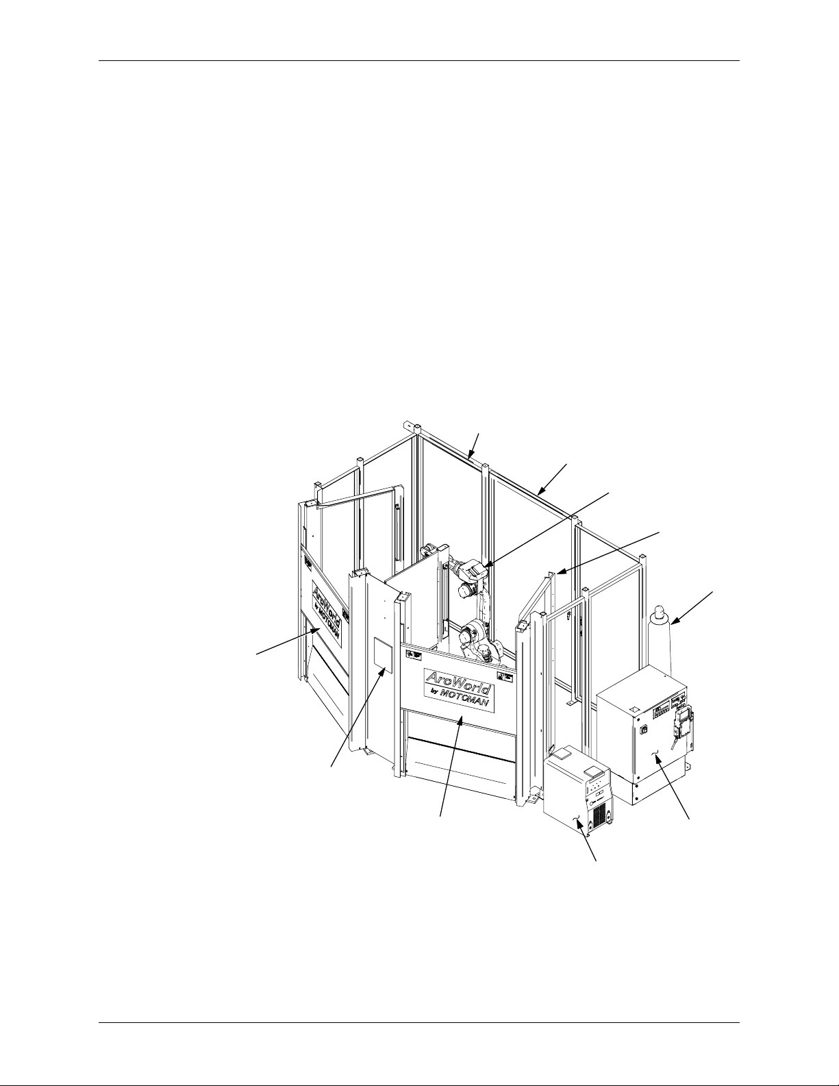
1.2 System Overview ..........................................................................................................1-2
1.2.1 System Layout ................................................................................................1-2
1.2.2 Major Components .........................................................................................1-3
1.2.3 Optional Equipment ........................................................................................1-3
1.3 Reference to Other Documentation................................................................................1-3
1.4 Customer Service Information ......................................................................................1-4
2 SAFETY
2.1 Introduction..................................................................................................................2-1
2.2 Standard Conventions ..................................................................................................2-2
2.3 General Safeguarding Tips............................................................................................2-3
2.4 Mechanical Safety Devices ...........................................................................................2-3
2.5 Installation Safety .........................................................................................................2-4
2.6 Programming Safety.....................................................................................................2-4
2.7 Operation Safety ...........................................................................................................2-5
2.8 Maintenance Safety.......................................................................................................2-6
3 EQUIPMENT DESCRIPTION
3.1 UP-series Robot Description ........................................................................................3-1
3.2 XRC 2001 Controller ....................................................................................................3-1
3.2.1 Playback Panel ...............................................................................................3-2
3.2.2 Programming Pendant ....................................................................................3-3
3.2.3 Brake Release .................................................................................................3-6
3.3 Operator Station............................................................................................................3-6
3.3.1 Cycle Start ......................................................................................................3-6
3.3.2 AUTO/MANUAL ..............................................................................................3-7
3.3.3 Emergency Stop (E-STOP) ..............................................................................3-7
3.4 Barrier Assembly ..........................................................................................................3-7
3.4.1 Stationary Weld Tables ...................................................................................3-7
3.5 Safety Features .............................................................................................................3-8
3.5.1 Arc Screens ....................................................................................................3-8
3.5.2 Fencing ...........................................................................................................3-8
3.5.3 Emergency Stops (E-STOPS) ..........................................................................3-8
3.5.4 ENABLE Switch ...............................................................................................3-9
3.5.5 Interlocked Cell Door ......................................................................................3-9
3.5.6 Light Curtains .................................................................................................3-9
3.5.7 Brake Release .................................................................................................3-9

ArcWorld II-200 System Manual ii
MOTO
MAN
Section Page
3.6 Welding Equipment ......................................................................................................3-9
3.6.1 Power Sources ................................................................................................3-9
3.6.2 PWF4 Wire Feeder ........................................................................................3-11
3.6.3 Universal Welding Interface (UWI) ................................................................3-11
3.6.4 GMAW Torch ................................................................................................3-11
3.6.5 Motoman Torch Mount .................................................................................3-11
4 INSTALLATION
4.1 Materials Required........................................................................................................4-1
4.1.1 Customer-Supplied Items ...............................................................................4-1
4.1.2 List of Tools ....................................................................................................4-1
4.2 Site Preparation............................................................................................................4-2
4.3 Removal from Shipping Skid........................................................................................4-3
4.3.1 Unloading Procedures ....................................................................................4-3
4.4 Cell Components..........................................................................................................4-4
4.4.1 List of Components ........................................................................................4-4
4.5 Assemble Cell Components..........................................................................................4-5
4.5.1 Setting Up the Cell ..........................................................................................4-5
4.6 Leveling and Securing the Equipment...........................................................................4-5
4.7 Removing the Shipping Brackets/Bolts.........................................................................4-6
4.7.1 Robot Shipping Brackets Removal ..................................................................4-6
4.7.2 Positioner Shipping Bolts Removal ................................................................4-7
4.8 Connecting the Cables..................................................................................................4-8
4.8.1 Connecting the Earth Ground ..........................................................................4-8
4.8.2 Connecting the Robot Cables .........................................................................4-8
4.8.3 Connecting the Com-Arc III and the Wire Cutter (Optional) ............................4-9
4.8.4 Connecting Water Circulator (Optional) ..........................................................4-9
4.9 Connecting the Power.................................................................................................4-11
4.10 Conducting a Safety/Operation Check ........................................................................4-12
4.11 Installation of Tooling and Fixtures.............................................................................4-12
5 OPERATION
5.1 Programming................................................................................................................5-1
5.1.1 I/O Assignment ...............................................................................................5-1
5.2 Daily Operation.............................................................................................................5-3
5.2.1 Start-Up ..........................................................................................................5-3
5.2.2 Robot Home (Cube 24) Position .....................................................................5-3
5.2.3 Starting the Master Job ...................................................................................5-3
5.2.4 Perform Operation Cycle .................................................................................5-4
5.2.5 Shutdown .......................................................................................................5-4

MOTO
MAN
iii ArcWorld II-200 System Manual
Section Page
5.3 System Recovery ..........................................................................................................5-5
5.3.1 Alarms and Errors ...........................................................................................5-5
5.3.2 Error Messages ...............................................................................................5-5
5.3.3 Door Default Settings ......................................................................................5-5
5.3.4 Shock Sensor Recovery ..................................................................................5-6
5.3.5 E-STOP Recovery ...........................................................................................5-6
5.3.6 Using the Brake Release .................................................................................5-7
6 MAINTENANCE
6.1 Periodic Maintenance...................................................................................................6-1
INDEX
LIST OF FIGURES
Figure Page
Figure 1-1 System Layout...........................................................................................................1-2
Figure 3-1 XRC 2001 Controller.................................................................................................3-1
Figure 3-2 Controller Playback Panel.........................................................................................3-2
Figure 3-3 Programming Pendant..............................................................................................3-3
Figure 3-4 RS-232C Serial Port..................................................................................................3-5
Figure 3-5 Enable Switch............................................................................................................3-5
Figure 3-6 Operator Station........................................................................................................3-6
Figure 3-7 Available Power Sources.........................................................................................3-10
Figure 4-1 Area Needed for Installation......................................................................................4-2
Figure 4-2 Remove Shipping Bolts.............................................................................................4-3
Figure 4-3 System Components.................................................................................................4-4
Figure 4-4 Leveling Bolts...........................................................................................................4-6
Figure 4-5 Location of Robot Shipping Brackets........................................................................4-6
Figure 4-6 Location of Positioner Shipping Bolts.......................................................................4-7
Figure 4-7 Connecting Robot to the Controller...........................................................................4-9
Figure 4-8 Water Circulator Connections.................................................................................4-10
Figure 4-9 Incoming Power Connections.................................................................................4-11
LIST OF TABLES
Table Page
Table 3-1 Weld Table Specifications ............................................................................................3-7
Table 5-1 XRC 2001 User Inputs .................................................................................................5-2
Table 5-2 XRC 2001 User Outputs ...............................................................................................5-2
Table 6-1 Periodic Maintenance ..................................................................................................6-1
This manual suits for next models
1
Table of contents