Yeasn YF-100 User manual

YF-100
Slit Lamp
User Manual
Version: 1.4
Revision Date: 2023. 01

Product Name: Slit Lamp
Nome do produto: Lâmpada de fenda
Nombre del producto: Lampara de hendidura
Ürün Adı: Biomikroskop
Nome prodotto: Lampada a fessura
Produktname: Spaltlampe
Nom du produit: Lampe à fente
Име на продукта: Прорезна лампа
Produkto pavadinimas: Plyšinėlempa
Nazwa produktu: Lampa szczelinowa
Název produktu: Štěrbinová lampa
Toote nimi: Pilu lamp
Produkta nosaukums: Spraugas lampa
Όνομα προϊόντος: Σχισμοειδή λυχνία
Numele produsului: Lampăcu fantă
Productnaam: Spleetlamp
User Manual Download link: www.yeasn.com/en/
Link para download do manual do usuário: www.yeasn.com/en/
Manual de usuario Enlace de descarga: www.yeasn.com/en/
Kullanım Kılavuzu İndirme linki: www.yeasn.com/en/
Manuale d'uso Link per il download: www.yeasn.com/en/
Link zum Herunterladen des Benutzerhandbuchs: www.yeasn.com/en/
Lien de téléchargement du manuel d'utilisation: www.yeasn.com/en/
Линк за изтегляне на ръководството за потребителя: www.yeasn.com/en/
Naudotojo vadovo atsisiuntimo nuoroda: www.yeasn.com/en/
Link do pobrania instrukcji obsługi: www.yeasn.com/en/
Uživatelská příručka Odkaz ke stažení: www.yeasn.com/en/
Kasutusjuhendi allalaadimise link: www.yeasn.com/en/
Lietotāja rokasgrāmatas lejupielādes saite: www.yeasn.com/en/
Εγχειρίδιο χρήστη Σύνδεσμος λήψης: www.yeasn.com/en/
Link de descărcare manual de utilizare: www.yeasn.com/en/
Gebruikershandleiding Downloadlink: www.yeasn.com/en/

Preface
Thank you for purchasing and using our Slit Lamp.
Please read this User Manual carefully before using this device. We sincerely
hope that this User Manual will provide you with sufficient information to use the
device.
Our pursuit is to provide people with high-quality, complete-function and more
personalized devices. Information in promotional materials and packing boxes is subject
to changes due to performance improvement without additional notice. Chongqing
Yeasn Science - Technology Co., Ltd. reserves the rights to update the devices and
materials.
If you have any questions during using, please contact at our service hotline: (86-023)
62797666, we will be very happy to help you.
Your satisfaction, our impetus!
Information of manufacturer
Name: CHONGQING YEASN SCIENCE - TECHNOLOGY CO., LTD
Address: 5 DANLONG ROAD, NAN’AN DISTRICT, CHONGQING, CHINA.
Tel: 86-23 62797666

Content
1. Specifications ............................................................................................................... 1
1.1 Uses .................................................................................................................... 1
1.2 Microscope ......................................................................................................... 1
1.3 Slit Illumination.................................................................................................. 1
1.4 Base movement .................................................................................................. 1
1.5 Chin Rest unit..................................................................................................... 2
1.6 Voltage ............................................................................................................... 2
1.7 Weight and dimension........................................................................................ 2
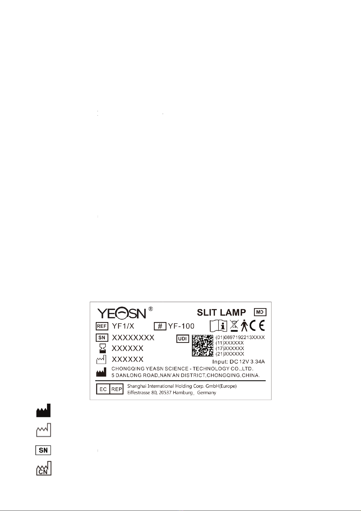
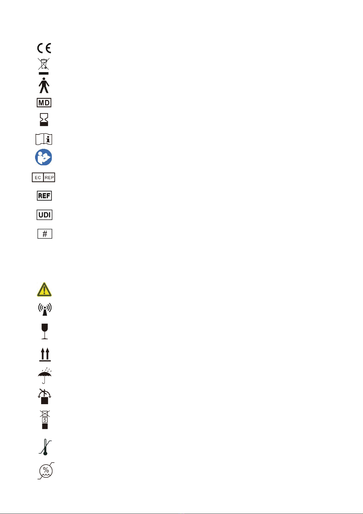
1.8 Name plate and indications ................................................................................ 2
2. Safety Precautions ........................................................................................................ 4
3. Instrument structure...................................................................................................... 6
4. Installing..................................................................................................................... 11
4.1 Parts list ............................................................................................................ 12
4.2 Accessories list ................................................................................................. 12
4.3 Installing steps.................................................................................................. 13
4.3.1 Install Head rest unit (C) ............................................................................... 13
4.3.2 Install base unit (D) ....................................................................................... 13
4.3.3 Install Rail cover (E) ..................................................................................... 14
4.3.4 Install Slit projector unit (B).......................................................................... 14
4.3.5 Install Eyepiece unit (A)................................................................................ 15
4.3.6 Install Breath screen (F) ................................................................................ 15
4.3.7 Connect the plug............................................................................................ 16
4.4 Checking after installing................................................................................... 16
4.4.1 Power connection .......................................................................................... 16
4.4.2 Check each unit ............................................................................................. 16
5. User instruction .......................................................................................................... 17
5.1 Preparation before use ...................................................................................... 17
5.1.1 Diopter compensation accommodation ......................................................... 17
5.1.2 PD adjustment ............................................................................................... 18
5.2 Locate the head of the testee............................................................................. 19
5.2.1 Locate the head of the testee.......................................................................... 19
5.2.2 Fix the sight line of the testee........................................................................ 19
5.3 Three-dimensional location of the base operation object................................. 19

5.4 Illumination adjustment.................................................................................... 20
6. Maintenance ............................................................................................................... 22
6.1 Replace Chin-rest papers.................................................................................. 22
6.2 Maintenance and care ....................................................................................... 22
7. Cleaning and protection.............................................................................................. 22
8. Environmental Conditions and Service Life .............................................................. 22
9. Troubleshooting guide................................................................................................ 23
10. Circuit diagram......................................................................................................... 24
11. Manufacturer’s Responsibility ................................................................................. 24
12. Disposal and Environmental protection ................................................................... 24
13. Guidance of EMC and other interference................................................................. 25

1
1. Specifications
1.1 Uses
For eye examination and aid in the diagnosis.
Contraindications: none.
Target groups of patients: adults, children.
Intended users: optometrists in hospital ophthalmology and optical shops.
The people who use this product are ophthalmologists in hospitals or clinics, and optometrists in
optical shops. To operate this product, they should have relevant knowledge of eye examinations and
have the relevant skills to operate the product.
1.2 Microscope
1) Type Galileo binocular converging
2) Model of magnifying 5 steps by drum rotation
3) Eyepieces 12.5×
4) Total magnification rate 6.4×, 10×, 16×, 25×, 40×
5) Range of PD adjustment 55mm to 80mm
6) Diopter adjustment -5.00D to +5.00D
1.3 Slit Illumination
1) Slit Width 0mm to 14mm continuous (become a circle at 14mm)
2) Slit Length 1mm to 14mm continuous
3) Slit Apertures φ0.3mm, φ5.5mm, φ9mm, φ14mm
4) Slit Rotation 0° to 180°continuous adjustable from vertical to horizontal direction
5) Filters Heat absorption, redfree, cobalt blue
6) Illumination white LED bulb, brightness adjustable (lx)
1.4 Base movement
1) Longitudinal (In/Out) Movement 100mm
2) Lateral (Left/Right) Movement 100mm
3) Vertical (Up/Down) Movement 30mm
4) Horizontal Movement 10mm

1.5 Chin
1) Chin R
e
2) Fixatio
n
1.6 Volt
a
1) Power i
n
2) Output
o
3) Output
v
1.7 Wei
g
1) Packag
e
2) Overall
3) Net wei
* The des
i
notice.
1.8 Nam
e
Name plat
e
In case th
e
contact au
t
M
D
S
e
C
o
Rest uni
t
e
st Elevatio
n
n
light
ag
e
n
put of ada
p
o
f adaptor:
v
oltage
g
ht and d
i
e
Dimensio
n
weight
ght
i
gn and sp
e
e
plate a
n
e
and indic
a
e
name pl
a
t
horized di
s
M
anufacture
r
ate of man
u
e
rial numb
e
o
untry of
m
t
n
p
tor:
1
1
i
i
mension
n
6
1
1
e
cifications
n
d indica
t
a
tions are p
a
a
te is not p
s
tributors.
r
u
facture
er
m
anufacture
70m
m
Red
L
1
00-240 V
A
1
2 V DC 3.
3
i
lluminatin
g
6
30mm×46
1
8.5kg
1
5 kg
are subject
t
ions
a
sted on th
e
asted well
2
m
L
ED
A
C, 50/60
H
3
4 A; 40 V
A
g
lamp 3V,
0mm×400
m
to change
s
e
instrume
n
or the cha
r
H
z; 1.0-0.5
A
A
fixation po
i
m
m
s
due to tec
t to arise e
n
r
acters bec
o
A
i
nt lamp 3
V
hnical upd
a
nd
-users' no
o
me uncle
a
V
a
tes withou
t
tice.
a
r to recog
n
t
additiona
l
n
ize, pleas
e
l
e

3
CE marking
Correct Disposal of This Product (Waste Electrical & Electronic Equipment)
The applied part of the device is Type B (Head rest unit)
Medical device
Use-by date
Consult instructions for use
Refer to instruction manual / booklet
Authorized European representative
Catalogue number
Unique Device Identifier
Model number
G.W. Gross Weight
DIM. Dimension
Attention! Please refer to accompanying documents
Nonionizing radiation
Fragile, handle with care
This way up
Keep dry
Do not roll
Stacking limit by 5
Temperaturelimit
Humidity limitation

4
Atmospheric pressure limitation
We will make available on request circuit diagrams, component part lists, descriptions that will
assist service personnel to repair those parts of ME equipment that are designated by the
manufacturer as repairable by service personnel.
2. Safety Precautions
The slit lamp is an instrument consisting of a high-intensity light source that can be focused to
illuminate the eyes with a thin beam of light. The binocular slit-lamp examination provides a
stereoscopic magnified view of the eye structures, which can be used for examination and auxiliary
diagnosis of a variety of eye conditions.
Please read the following matters needing attention carefully in case of personal injury, device
damages or other possible hazards:
●To avoid operation in flammable or explosive environment with dust, or high temperatures.
For indoor use only, keep the slit lamp clean and dry.
●To avoid operation near water and prevent any kind of liquid drop on the instrument.
●To avoid place in humid, dusty, or rapid humidity and temperature variation ambient conditions.
●Dedicated power adaptor configured for the device should be used: model GSM40A12
(component of device), Input 100V~240V 50/60Hz, Output 12V 3.34A.
●Do not plug in patch board or power extension cords.
●For emergency situations, cut off the power supply firstly, but avoid pull the power cord.
●Wet hand is not allowed to touch power to avoid shock.
The power cord is forbidden to tread, knot and place heavy object on.
●Not position the device to make it difficult to disconnect the supply mains.
●Check the power cord frequently and before operating to avoid fire and electric shock.
●Disconnect the plug before clean and disinfection.
●Cut off power and put on dust cover when not using it.
●To prevent the instrument from falling and breakdown, it shall be properly installed or placed on
a sound and hard surface, with an inclination angle of less than 10°
●Do not disassemble the instrument or change the electrical system.
●In case of moving the installed instrument in short distance, please lock all movable parts. During

5
movement, please push with hand holding the table top with hand or hold with two hands. If it is
long distance movement, please put it back to the original package firstly.
●Electrical medical devices and systems are subject to special EMC measures and must be
installed in accordance with the EMC instructions contained in this accompanying document.
-Portable and mobile HF communication systems may interfere with electrical medical devices.
-The operation of other lines or equipment than those listed may lead to higher emissions or may
reduce the device's resistance to interference.
- Do not use a power adaptor that is not configured with the device, otherwise it may increase the
electromagnetic emission amount, which may reduce the capacity of resisting disturbance.
●In case of a problem, please refer to the troubleshooting guide.
●Do not serviced or maintained while in use with the patient.
●Notification:Any serious event related to the device to the user and/or patient shall be reported to
the manufacturer and competent authority of the Member State where the user and/or patient is
located.
Caution: The user is cautioned that changes or modifications not expressly approved by the
party responsible for compliance could void the user's authority to operate the equipment.

6
3. Instrument structure

7
○
1 On/Off Switch
Main power switch of slit lamp.
○
2 Accessories Drawer

8
Storage the focusing test rod and other accessories.
○
3 Table top
Mounting substrate of each component,
Platform used by the operator.
○
4 Base
Supports the microscope and the illumination arms, control the horizontal movement of slit lamp.
○
5 Joystick
Incline joystick to move the instrument slightly in the horizontal surface and rotate it to adjust the
elevation of the microscope.
○
6 Intensity Control Knob
Continuous adjustment the illumination.
○
7 Filter Base
Changing filters by turning the base and meet requirement of various inspections.
○
8 Slit Apertures Adjustment Base
Changing the Slit Apertures by turning the base.
○
9 Breath Screen
It can stop the breath between the operator and testee in order to avoid embarrassment.
○
10 Fixing screw for Breath Screen
Install the breath screen.
○
11 Fixation light
Show the eye-gaze direction of testee and position the eyeball of testee.
○
12 Slit Projector Head
The core parts of slit imaging, do not scratch the optical surface in order to avoid effect of image
quality.
○
13 Slit Rotation Scale
Indicate the slit rotation angle.

9
○
14 Slit Width Knob
The slit width is continuous adjustable.
○
15 Illumination Angle Ring
The long line on illumination base and value on corresponding lamination angle ring show the angle
of two arms, indicate the angle between observation and illumination direction.
○
16 Illumination Angle Base
○
17 Linkage Knob
Turn this knob, slit projection system and microscope arm are in linkage moving state.
○
18 Microscope Arm Locking Knob
Locks the rotational movement of microscope arm and make it not able to turn in order to make the
positioning of observation easily.
○
19 Rail Cover
To protects the rail surface.
○
20 Power socket
Supply power to slit lamp through power cord.
○
21 Focusing Ring
Adjust the eyepiece diopter in order to get clear image before use.
○
22 Connector Locking Knob
When the instrument need maintenance, take apart the observation parts and clean the lens by loose
the knob.
○
23 Dispersion Lens
Used for enlarging illumination filed under low magnification ratio.
○
24 Accessory Interface
Installation of tenonometer and other accessories.
○
25 Magnification dial
Changing the magnification ratio.

10
○
26 Moveable Arm
Supporting the observation parts, confirm the observation angle by turning the arm.
○
27 Slit Base
Change the slit direction by turning the slit base.
○
28 Illumination Base
○
29 Instrument Base Locking Knob
Lock the knob, the instrument base will be fixed.
○
30 Slide Plate
Make the base move by moving joystick on the slide plate.
○
31 Head Rest
Support the fore head of the testee, position the head of the testee.
○
32 Eye Position Mark
When the horizontal center of testee’ eye in the same horizontal plane of this mark, then the
microscope height which controlled by joystick is at the centering position.
○
33 Chin-Rest Fixed Pin
Fix the paper on the chin-rest.
○
34 Chin-rest
Support the chin of the testee, position the head of the testee.
○
35 Chin-rest Adjustment Knob
Adjust the height of chin rest by turning the knob.
○
36 Illumination cable

11
4. Installing
This instruction manual is for YF-100 Slit Lamp. All parts must be taken out carefully from the
package, and then be put on installing.

12
4.1 Parts list
No. Parts name Qty. Note
A Eyepiece unit 1
B Slit projector unit 1
C Head rest unit 1
D Base unit 1
E Rail covers 2
F Breath screen 1
G Workbench 1
The three units are already
installed well into a component
R Power box 1
S Accessories box 1
H Power adaptor 1
4.2 Accessories list
No. Parts name Qty. Note
J Dust plate 1
L Focusing test rod 1
M Dust cover 1
P Connector locking knob 1
O Allen key(4mm) 1 Installing tool
N Allen key(5mm) 1 Installing tool
T Yellow filter unit 1
U Hexagon socket screw (M5) 2

13
4.3 Installing steps
4.3.1 Install Head rest unit (C)
1) Place the head rest unit (C) and workbench (G) as shown in Figure 1.
2) After aligning the screw holes, use an allen wrench (N) to tighten the two hexagon socket screws
(U).
Figure 1
4.3.2 Install base unit (D)
1) Install the gear wheels of both sides of Base unit (D) on the gears of workbench (G).
2) Note that the gear wheel should be installed in corresponding place of gear (Figure 2), then check
if the Base unit (D) can roll steadily forward and backward on workbench (G).
3) Connect the Illumination cable.
Figure 2

14
4.3.3 Install Rail cover (E)
1) Align the insert of the rail cover with the groove at the bottom of the rack;
2) Insert the rack cover in the direction shown (Figure 3).
Figure 3
4.3.4 Install Slit projector unit (B)
1) Drive out the hexagon socket countersunk head screws (Figure 4) beneath the central shaft of Slit
projector unit (B) with the allen key (O).
Figure 4
2) Connect the central shaft of Slit projector unit (B) to connection base of Base unit (D) , then
tighten the hexagon socket (O) countersunk head screws with the allen key (O) (Figure 5).
3) Connect the plug below the slit projection part (B) to the corresponding socket above the
workbench (G).

15
Figure 5
Note: when connecting the central shaft and connection base, the locating pin on connection
base should be positioned in the locking slot on the central shaft.
4.3.5 Install Eyepiece unit (A)
Take the Eyepiece unit (A) out carefully; Install the U-groove on the bottom of the Eyepiece unit (A)
into the U-guide which supports the bent arm. Tighten the connector locking knob (P) after the front
part of U-groove getting close to the connector locking knob (Figure 6).
Note: please do not touch the optical lens in the process of installing Eyepiece unit.
Figure 6
4.3.6 Install Breath screen (F)
1) Put the installing hole of breath screen (F) through the hook of the Eyepiece unit (A).
2) Strip off the protective film on breath screen. Breath screen can be removed and independently
kept when not being used.
Table of contents
Other Yeasn Medical Equipment manuals