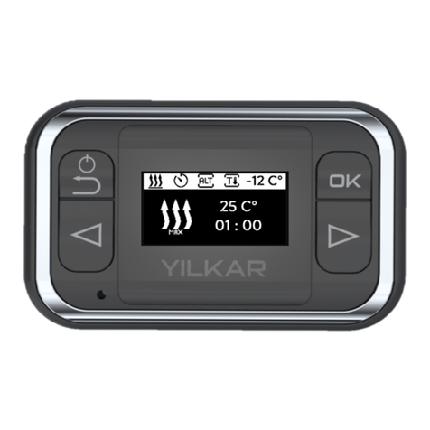
YILKAR YH Basic User manual

EN
YH Basic
Operating instructions
YH BASIC Control Panel

Contents
1 Warranty and liability ......................................................1. 3
Introduction .................................................................................1. 3
2.Safety ......................................................................................... 3
3.Overview .................................................................................... 4
4.Heating operation ........................................................................ 5
5.Ventilation Operation ................................................................... 6
6.Error reporting ............................................................................ 6
7.Set Temperature Control ............................................................ 7
7.1 Standart mode ................................................................. 7
7.2 Room thermostat mode ................................................... 7
8.Resetting the Device .................................................................... 8
9.Information Screen ........................................................................ 8
10.Cleaning ..................................................................................... 8
11.Error codes ................................................................................. 9
11.Technical information ................................................................. 15

3
1. Introduction
To fully enjoy the comfort of your Yılkar heater, please read this user manual carefully. If you have
additional questions regarding assembly or operation, please contact your specialist dealer or
Yılkar service. The experts here will gladly provide you with reliable and expert knowledge.
Please keep this manual carefully.
We wish you a good trip.
This manual is part of the device and contains information for the user to use the device safely.
The operator's manual describes all the functions of the control panel. If you have any questions,
please contact service and / or customer service.
This user manual should be forwarded to the next owner of the device.
1.1 Warranty and liability
Yılkar accepts no liability for defects, damage and damages caused by non-compliance with the
installation instructions and user manual, as well as the warnings provided within them.
This disclaimer applies especially to:
Improper use
Repairs not carried out by a Yılkar service workshop
Use of non-genuine parts
Conversion of the unit without permission from Yılkar
2. Safety
Explosion hazard in environments with flammable vapors, flammable gas and hazardous
materials (eg gas stations, storage tanks, fuel, coal, wood or grain tanks)
Do not switch on or operate the heater !!
Warning !
Inhalation of toxic gases in confined spaces, danger of poisoning and suffocation
The heater should never be operated in confined spaces such as garages or workshops
without exhaust gas discharge, including the programming function !!
Warning !
Fire hazard due to flammable materials or liquids in the hot air stream (Air heater).
Do not block hot air flow !!
Warning !

1
1Heating On / Off button
Heater shutdown button (5 seconds)
2Ventilation On / Off
2 4
3
3. Overview
4
65
3Increase direction button
4Decrement direction button
5Ambient temperature sensor
6Display screen
Ventilation active
Heating active
Error alert
Symbols :

4. Heating operation
Heating start
Pressing the button with the heating icon starts the
heating mode.
The YH Basic control panel controls the air heater based on the SET value.
In case of heating, the heating sign appears on the screen.
Heating setting
The set setting can be easily changed while in heating. Follow the instructions.
5
Increasing or decreasing the set temperature can be
done with the arrow keys.
For the function of the set temperature, see. s. 7
Heating stop
If you press the button with the heating icon, the heater
will stop if heating is active.
The heating sign will disappear from the screen.
Attention! If you press the fan button while in heating state, the heating stops
again. The device starts to fan.
Your heater starts heating with the temperature you set last.

5. Ventilation Operation
Ventilation start and stop
6
Pressing the button with the ventilation icon will start
the ventilation mode.
The YH Basic control panel controls the air heater based on the SET value.
In case of ventilation, ventilation sign appears on the screen.
If you press the button with the ventilation icon again,
the ventilation mode is stopped.
Attention! If you press the heating button while the ventilation is on, the ventilation
stops again. The device starts heating.
6. Error reporting
If the device detects any error, it will show an error code on
the screen.
You can find information about the problem and how to fix it
from the error table.
For the error table, see. p.7

Your heater heats at maximum level until it reaches the set temperature.
If the set temperature is reached, it goes into standby mode.
If the ambient temperature falls below the set value, it will reactivate and heat.
7. Set Temperature Control
7.1 Standart mode
It contains a temperature sensor where it senses the
ambient temperature in the section where the air circulation
is located in your heater. Your heater transfers the medium
to the set temperature by making a comparison according to
the temperature detected by this sensor as a standard.
7.2 Room thermostat mode
There is one temperature sensor on your control panel to detect the ambient temperature. If
you switch your device to room thermostat mode, your heater will compare the temperature
perceived by this sensor and bring the environment to the set temperature.
To activate the room thermostat mode, consult your
Yılkar authorized service center or follow the instructions
specified in the installation instruction.
SET temperature setting range is between 10 °C and 35 °C.
Your heater starts showing the ambient temperature
it senses 300 seconds after starting the heating.
The term "temp" means that the ambient temperature
is displayed.
The term "temp" indicates that you are in Standard
mode.
The phrase "RTemp" indicates that you are in Room
thermostat mode.
7

8
8. Resetting the Device
If you press the button with the close icon for more
than 5 seconds, the button turns itself off.
If you press the on button again, the button will reset
your heater by turning it on.
If it resolved the error; the error will be removed from the screen.
If the error is not resolved; the device re-detects the error.
The software version information related to the connected
control panel is displayed on the start screen.
The demonstration switches to the main menu after 3
seconds.
9. Information Screen
10. Cleaning
Please use only a soft, lint-free cloth for cleaning the control panel.
Moisture should not get into the body.
Do not use glass cleaners, household cleaners, sprays, solvents, alcohol-containing or abrasive
cleaners.
It is forbidden to include the control panel in domestic waste.
Please observe the national legal regulations on waste management for electronic products.
Error indication E 17 means there is a communication problem.
To solve the problem, the heater must be de-energized and re-
applied.
It is not possible to reset from the button.

9
10. Error codes
Cause: The cable may be cut or the socket may be disconnected. The glow plug may be defective or
broken.
Device Response: When the device sees the error, it wants to switch to stop mode. If the system is
hot, it will operate cooling mode before stopping.
Troubleshooting:
* Check glow plug cable and sockets.
* Remove the spark plug and check the internal resistance test.
YH 12 Volts - 0.6 Ω + - 0.1 Ω
YH 24 Volts - 1.6 Ω + - 0.2 Ω
* If the resistance values are not within this range, replace the glow plug.
* Reset the device from the button or disconnect the power supply and then connect again.
E 01 : Glow Plug Open Circuit
Cause: Cable may be cut or short-circuited.
Device Response: When the device sees the error, it wants to switch to stop mode, if the system is
hot, it will operate cooling mode before stopping.
Troubleshooting:
* Check glow plug cable and sockets.
* Remove the glow plug and check it by performing a current test.
8 volts - 7.8A ± 1.5A @ 20 ° C
18 volts - 5.2A ± 0.5A @ 20 ° C
* If the values are not in this range; Replace the glow plug.
* If no problems are observed in the cable, sockets and current test, replace the YHC.
* Reset the device from the button or disconnect the system from the power supply and connect again.
E 02 : Glow Plug High Current
Cause: The cable may be cut or the socket may be disconnected. The fuel pump may have failed.
Device Response: If the system detects an error while in the stop mode, the system will not operate
and an error will appear on the screen. If the pump is in an open state while the system is running, the
system will likely go into stop mode by cooling to detect that the flame has gone out (E19) or that the
combustion has not started (E15).
Troubleshooting:
* Check the fuel pump cable and connectors.
* Disconnect the fuel pump connector (J7) and measure the resistance value of the fuel pump.
12v pump - 5 Ω ± 0.5 Ω
24v pump - 20.8 Ω ± 0.5 Ω
If the resistance does not match, replace the fuel pump.
If the resistance is correct, reconnect the fuel pump.
* YH Disconnect the external connector J8-J9 and measure the resistance between pins 3 and 4 on J9
if it is OK (approx.2 Ω); Replace the YHC.
* Reset the device from the button or disconnect the system from the power supply
and connect again.
E 03 : Fuel Pump Open Circuit

10
Cause: Cable may be cut or short-circuited.
Device Response: If the system detects an error while in the stop mode, the system will not operate
and an error will appear on the screen. If the pump is short-circuited while the system is running, the
system will likely go into stop mode by cooling to detect that the flame has gone out (E19) or that the
combustion has not started (E15).
Troubleshooting:
* Check the fuel pump cable and connectors.
* Disconnect the fuel pump connector, if fault code E03 (Fuel Pump Open Circuit) is displayed, the fuel
pump is faulty. Replace the fuel pump.
* If the fault code E04 remains the same, disconnect the connector YH External connector J8-J9 and
check that pin 3 (blue wire) on J9 is shorted to ground (pin 1) to the fuel pump. If it is OK, replace YHC.
E 04 : Fuel Pump High Current
Cause: The cable may be cut or the socket may be disconnected. The fan motor may have failed.
Device Response: If the system detects an error while in the stop mode, the system will not operate
and an error will appear on the screen. If the fan motor is open while the system is running, the system
will likely go into stop mode by cooling to detect that the flame has gone out (E19), that the combustion
has not started (E15), or that the fan will detect a malfunction.
Troubleshooting:
* Check the fan motor cable and sockets.
* Unplug the fan motor cable from the YHC and perform a resistance test. If the resistance test is
smooth; Replace the YHC.
* Reset the device from the button or disconnect the system from the power supply and connect again.
E 05 : Blower Motor Open Circuit
Cause: Cable may be cut or short-circuited. If any part enters the suction impeller side while the
device is operating, this malfunction may occur as a result of the fan's current rise if an impeller
prevents rotation of the impeller. If the magnetic field reader on the YHC is prevented from seeing the
impeller, this fault may occur as the current will rise again.
Device Response: If the system detects an error while in the stop mode, the system will not operate
and an error will appear on the screen. If the fan motor overcurrent detection occurs while the system
is running, the system will go to stop mode.
Troubleshooting:
* Check the fan motor cable, sockets, and device impeller to prevent operation.
* Apply current test to the fan motor. To do so, pull the socket out of the motherboard.
Apply 8v voltage to the fan motor for 12v, 18v for 24v, and measure the current strength after 40
seconds.
Current strength = <6A - Fan motor is OK. Replace the YHC.
Current> 6A - Replace fan.
* Reset the device from the button or de-energize the system. Restart the device if the error is
corrected and the system will continue to run smoothly.
E 06 : Blower Motor High Current

11
Cause: The cable may be cut or the socket may be disconnected. The indoor temperature sensor may
have failed.
Device Response: When the device sees the error, it wants to switch to stop mode.
Troubleshooting:
* Check the internal temperature sensor cable and sockets.
* Remove the internal temperature sensor and check by applying resistance test.
If the internal resistance is > 15KΩ değiştir, replace the internal temperature sensor.
* If the resistance test is OK, replace the YHC.
* Reset the device from the button or disconnect the system from the power supply and connect again.
E 07 : Indoor Temperature Sensor Open Circuit
Cause: The cable may be cut or the socket may be disconnected. The flame monitoring sensor may
have failed.
Device Response: When the device sees the error, it wants to switch to stop mode.
Troubleshooting:
* Check the internal temperature sensor cable and sockets.
* Remove the internal temperature sensor and check by applying resistance test.
If the internal resistance is > 70KΩ, replace the flame monitoring sensor. @ 20 ° C
* If the resistance test is OK, replace the YHC.
* Reset the device from the button or disconnect the system from the power supply and connect again.
E 08 : Flame Monitoring Sensor Open Circuit
Cause: The cable may be cut or the socket may be disconnected. The overheating sensor may have
failed.
Device Response: When the device sees the error, it wants to switch to stop mode.
Troubleshooting:
* Check the internal temperature sensor cable and sockets.
* Remove the internal temperature sensor and check by applying resistance test.
If the ohmic resistance is> 1200 Ω, replace the overheating sensor. @ 20 ° C
* If the resistance test is OK, replace the YHC.
* Reset the device from the button or disconnect the system from the power supply and connect again.
E 09 : Overheating Sensor Open Circuit
Cause: Cable may be cut or short-circuited.
Device Response: When the device sees the error, it wants to switch to stop mode. If the system is
hot, it will operate cooling mode before stopping.
Troubleshooting:
* Check the internal temperature sensor cable and sockets.
* Disconnect the internal temperature sensor connector, and reset the device from the button. If the
fault code E07 (Internal Temperature Sensor Open Circuit) is displayed, the internal temperature
sensor is faulty. Replace the internal temperature sensor.
* Or remove the internal temperature sensor and check by applying resistance test.
If the internal resistance is too low (about 0), there is a short circuit. Replace the internal
temperature sensor.
* If the resistance test is OK, replace the YHC.
*Reset the device from the button or disconnect the power supply and then connect again.
E 10 : Indoor Air Temperature Sensor High Current

12
Cause: Cable may be cut or short-circuited.
Device Response: When the device sees the error, it wants to switch to stop mode. If the system is
hot, it will operate cooling mode before stopping.
Troubleshooting:
* Check the flame monitoring sensor cable and sockets.
* Disconnect the flame monitoring sensor socket, and reset the device from the button. If the fault code
E08 (Flame Monitoring Sensor Open Circuit) is displayed, the flame monitoring sensor is faulty.
Replace the flame monitoring sensor.
* Or remove the flame monitoring sensor and check by applying resistance test.
If the internal resistance is too low, there is a short circuit. Replace the flame monitoring sensor.
* If the resistance test is OK, replace the YHC.
* Reset the device from the button or disconnect the power supply and then connect again.
E 11 : Flame Monitoring Sensor High Current
Cause: Cable may be cut or short-circuited.
Device Response: When the device sees the error, it wants to switch to stop mode. If the system is
hot, it will operate cooling mode before stopping.
Troubleshooting:
* Check overheating sensor cable and sockets.
* Disconnect the overheating sensor connector, and reset the device from the button. If the fault code
E09 (Overheating Sensor Open Circuit) is displayed, the overheating sensor is faulty. Replace the
overheating sensor.
* Or remove the overheating sensor and check it by performing a resistance test.
There is a short circuit if the ohmic resistance is too low. Replace the overheating sensor.
* If the resistance test is OK, replace the YHC.
* Reset the device from the button or disconnect the power supply and then connect again.
E 12 : Overheat Sensor High Current
Cause: The voltage increases to 30 volts for 24-volt devices and 15 volts for 12-volt devices and if the
supply is present for more than 20 seconds, the device detects high voltage failure.
Device Response: If the device detects this fault in stop mode, it will not allow the system to operate if
the voltage drops and becomes operational, the error goes away automatically and the system can be
started. If such an error occurs while the device is running, the device will send itself to the stop mode
by cooling and the error will remain on the screen.
Troubleshooting:
* Check that the supply voltage from the vehicle to the system is within the appropriate range.
YH 24v - Supply voltage < 30v.
YH 12v - Supply voltage < 15v.
* If the supply voltage is appropriate, reset the device from the button or disconnect the power supply
and then connect again.
E 13 : High Voltage Failure

13
Cause: The voltage drops below 21 volts for 24-volt devices and less than 10.5 volts for 12-volt
devices, and the device detects a low voltage failure if the supply voltage is present for more than 20
seconds.
Device Response: If the device detects this fault in stop mode, it does not allow the system to operate
if the voltage rises and becomes operational, the error goes away automatically and the system can be
started. If such an error occurs while the device is running, the device will send itself to the stop mode
by cooling and the error will remain on the screen.
Troubleshooting:
* Check that the supply voltage from the vehicle to the system is within the appropriate range.
YH 24v - Supply voltage> 21v.
YH 12v - Supply voltage> 10.5v.
* The voltage on the vehicle battery must not different from the voltage on the J9 connector. If this is
the case, please note that the “+” terminal of the battery is in contact with oxidation or contact.
* If the supply voltage is appropriate, reset the device from the button or disconnect the power supply
and then connect again.
E 14 : Low Voltage Failure
Cause: The fuel tank may be out of fuel, the fuel hose may be clogged, the exhaust hose may be
clogged, or the combustion air intake hose may be clogged. The glow plug may have failed and the
fault could not be detected electrically.
Device Response: If the device does not detect combustion in the combustion chamber shortly after it
starts working, it tries to start the combustion again after cooling for a while. If it encounters the same
situation 2 times in a row, it will give the error.
Troubleshooting:
* Make sure the exhaust outlet and combustion air intake hoses are not blocked or improperly installed.
* Make sure there is fuel in the fuel tank.
* Make sure the fuel hose is not blocked.
* Make sure glow plug is working.
* Try to start the device after refueling the fuel tank, if the device does not work in 2 attempts, it will give
the same error again, reset it from the button or disconnect the power supply and then connect again.
E 15 : Ignition Start Failure
Cause: The device may have overheated in any way during operation. The temperature sensor on the
housing or the temperature sensor in the suction line may be detecting temperatures that are higher
than required. If the power is cut off for any reason while the system is operating, this may occur when
the power is turned on again.
Device Response: When the device detects this error, it will go into stop mode by cooling if it is
working. It will clear the error if the device is reset or if the power is supplied and reconnected. If this
error occurs when the device is de-energized and turned on again, all the sensors on the device will
detect high temperature and the error will be displayed and the error will remain on the screen until the
reset is made with the button.
Troubleshooting:
* Make sure that there are no airflow obstructions in the air inlets and outlets of the device.
* Make sure that the pipe length between the device and the blowing grille is within the standards.
* Check the cables and sockets of the temperature sensors on the device.
* If a problem is not observed, reset the device from the button or disconnect
the power supply and then connect again.
E 16 : Overheating Failure

14
Cause: Deformation may occur in the cables that the device communicates with the control unit. There
may be a failure in the YHC or control panel.
Device Response: When the device detects this error, it will go into stop mode by cooling if it is
working.
Troubleshooting:
* Check the cables and sockets where the device communicates with the control unit.
* If there are no problems, replace the control unit and perform the necessary repair if there is
deformation in the cables or sockets.
* The device cannot be reset from the control panel !! Power down the system and give it again.
E 17 : Control Unit Communication Failure
Cause: While the device is operating, an element that prevents the operation of the fan may have
entered the device. The magnetic sensor may have malfunctioned. If the device is intervened, the
distance between the outside air impeller and the holder T plastic may be incorrectly set. There may
be elements that impede the operation of the propeller that delivers air to the combustion chamber.
For similar reasons, since the fan motor tries to maintain its operating speed, the current it uses may
increase and the device may see fan motor high current failure.
Device Response: When the device detects this error, it will switch to stop mode if it is working.
Troubleshooting:
* Make sure that no external elements get inside the device.
* Ensure that the distance between the outside air impeller and the holder T plastic is within the
standards.
* Make sure that the YHC is in the correct position.
* Be sure to reset the device from the button or disconnect the system from the power supply and
connect again.
E 18 : Fan Operating Failure
Cause: The fuel tank may be out of fuel or the fuel hose may be clogged. The combustion air intake or
exhaust outlet may be clogged or deformed. The exhaust line or indoor air intake line may be improperly
installed, with with inverse airflow into the device.
Device Response: If the device is working when it detects this error, it will switch to stop mode by
cooling.
Troubleshooting:
* Make sure the exhaust outlet and combustion air intake hoses are not blocked or improperly installed.
* Make sure there is fuel in the fuel tank.
* Make sure the fuel hose is not blocked.
* Try to start the device after refueling the fuel tank, if the device does not work in 2 attempts, it will give
the same error again, reset it from the button or disconnect the system from the power supply and
connect again.
E 19 : Combustion Stop Failure

15
Cause: Occlusion may occur on the air intake side or the outlet side during operation. There may be a
detection problem with the flame monitoring or overheating sensor.
Device Response: If the device is working when it detects this error, it will switch to stop mode by
cooling.
Troubleshooting:
* Make sure there is no blockage in the air intake and outlet of the device.
* After making sure of these situations, reset the device from the button or disconnect the system from
the power supply and connect again.
E 20 : Air Blockage Failure
Cause: YHC fault may have occurred.
Device Response: If the device is working when it detects this error, it will switch to stop mode by
cooling.
Troubleshooting: Replace YHC. After replacement, reset the device from the button or disconnect
the system from the power supply and connect again.
E 21 : EEPROM Failure
Cause: If the system is operated in room thermostat mode, there may be a malfunction of the
temperature sensor on the control unit.
Device Response: If the device is working when it detects this error, it will switch to stop mode by
cooling.
Troubleshooting:
* Replace the control unit.
* After replacement, reset the device from the button or disconnect the system from the power supply
and connect again.
E 20 : Control Unit Temperature Sensor Failure (Opsiyonel)
11. Technical information
The Control Unit is designed for Engine, Diesel Fuel Pump and Glow Plug 12 V and 24 V.
Control Panel and temperature sensor components are not voltage dependent.
Permissible ambient temperatures
Operation: –40 ° C to +40 ° C
Storage: –40 ° C to +90 ° C
Diesel fuel specified by the manufacturer according to DIN EN590 should be used. The use of additives
has no known adverse effects. If fuel is taken from the vehicle tank, follow the additional instructions
provided by the vehicle manufacturer.
Attention !
The installation instructions must be read and followed carefully before installing the heater
and operating the device. Regulations will be invalid and YILKAR will not take any
responsibility if improper installation or work is done or determined to be done.

Part No: URT.T.50a / 21.10.2019 / Rev.01 • The right to make changes is reserved. • Printed in Turkey • © Yılkar Airconditioned, 2020
Vehicle Heating Cooling and Ventilation Systems
Phone : +90 224 215 53 28 (pbx)
Fax : +90 224 215 99 24
Address : Küçükbalıklı Mah. 580.Sok
No:6 Osmangazi / BURSA / TURKEY
www.yilkarklima.com
Table of contents
Other YILKAR Control Panel manuals