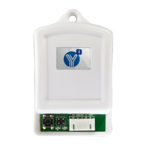
Yli Electronic YK-968 User manual

Model:YK-968
Touch One-door Access Controller
TECHNICAL PARAMETERS
FACTORY DEFAULT SETTINGS
NO
1
2
3
4
5
6
7
8
9
ITEM
Operating voltage
Operating current
Dimensions
Weight
Ambient temperature
Relative humidity
Storage
Card type (alternative)
Card reading distance
PARAMETER
DC 12V±10%
< 100mA
120mm x78mm x22mm
130g
-10℃70- ℃
20% 80%-
1000 users
EM(ID) card(IC card for option)
1-15CM
123456
Card or Access PIN
5secs
Auto
Off
Input
Programming Password
Open Mode
Output signal time
Backlight
Security function
WG26Port
LED AND BUZZER INDICATES
www.yli.cn We create security
test ed
Ger man y
EMC
R
Fast flash: light on 0.5sec,light off 0.5 sec Slow flash:light on 0.1 sec,light off 0.1sec
Standby State Red light(SlowFlash)
Unlocked state GreenLight(FastFlash)
Read card to open
(Enterpasswordthen press“#”)ValidCard:Greenlightkeepson ,1 shortbuzz
InvalidCard:3 shortbuzz
EnterAccessPIN to open Correct Password:Greenlightkeepson ,1 shortbuzz
Incorrect Password:3 shortbuzz
Card+AccessPin
(After Read card to enter Access Pin,thenPress
“#”)
InvalidCard:3 shortbuzz
ValidCard:GreenlightFastflash
Correct Password:Greenlightkeepson ,1 shortbuzz
Incorrect Password:3 shortbuzz
Programming operating state indication(Take the programming operating of adding Users
for example)
Steps soundand light hint
#GreenlightFastflash,1shortbuzz
123456# CorrectPass word:Redlightkeepson ,1 shortbuzz
WrongPassword:3 shortbuzz
1 Read Card GreenlightFastflash:1long buzz indicatecan add cards,3
shortbuzz indicate can’t add cards
#Inputcorrect:1long buzz
Inputwrong:3shortbuzz,Redlightslowflash,Meanwhile
Exit programmingstate

INSTALLING WIRING DIAGRAM
ACCESS CONTROL FUNCTION SETTING
Jp1 Jp2
www.yli.cn We create security
SILKPRINT COLOR FUNCTION
12V Red DC 12V Input
GND Black Power
PUSH Blue Low-leveloutput
OPEN Yellow DoorRelease
BELL Gray BELL
No.
1
2
3
4
5
6 BELL White
NO SILKPRINT COLOR FUNCTION NOTE
1 12V Red DC 12V Output
Somemodels
withoutthis
interface
2 GND Black Power
3 DATA0 Green WG dataline0
4 DATA1 White WG dataline1
5 NC Brown RelayNC Output
6 COM Blue Relay Com output
7 NO Purple RelayNO Output
PUSH
GND
12V
NC
NO
GND
(Access control power supply)
POWER Door Release BELL
Wg26 OUT/IN(this interface
only apply to some models)
Connect with Automatic
Door and Barrier
NC COM NO
Lock
Lock
+
+
12V GND DO D1
12V GND PUSH OPEN BELL BELL JP 1
JP 2
EXIT
DOOR
Programming Operating Instruction:(The programming Code Factory Defaults:123456)
NAME ContinualKey-Press(ReadCard)Operating NOTE
AddUser #programmingPassword#1ReadCard#
Add(Modify)Public
Accesspassword
#programmingPassword#21New
Password#
DeleteAll User
DeleteUser(ReadCard)
#ProgrammingPassword#400000
#ProgrammingPassword#410000
This operation willdelete
all users,but will not delete
Public Access Password
Continual Read Cardcan
delete multiple Cards at
one-time
Modify programming
Password
#programming Password#0 New
programming Password #Repeat the New
programming Password#
LOST PASSWORD:according
to the initial programming
operation
Continual Read Card can
add multiple Cards at
one-time
Only can set one set of
Public Access password:use
password to
access,input”password”,
then press #
Common
operation

www.yli.cn We create security
Extended
operation
Add personalAccess
Password
#ProgrammingPassword#22NEW
password#
Can set up multiple sets of
personal
password:Accessedby
Password,input password
then press#
Add User Card(input Card
Number) #ProgrammingPassword#23#Manual
inputinitialcard number
The Card Number can be
the 10 digits in the blank
spaceon the left side of the
Card or the 8 digits on the
right side of the card,the
machine identify automatic
Add UserCard(Continual
CardNumber)
#ProgrammingPassword#23#Manual
inputinitialcard number Card
Quantity#
The Card quantity must be
4 digits(input 0020 can add
20 cardsat one-time)
Add ”Card+Password”
User
#Programming Password#3ReadCard
NEW password#
Modify the corresponding
password, please refer to
the instruction of modifying
corresponding personal
Access password
DeleteUser(inputID No.) #Programming Password#42User ID
The UserID must be 4
digits,for example
0001,0020,etc.Details
shownin User ID
Instruction
Delete User(input Card
No.)
#Programming Password#43 Manual
input card number
Delete User(input
password)
Delete all Password User #Programming Password#45 1111#
Modify Relay unlocking
time
Set the open mode #Programming Password# 6 x x #
Cardreaderfunction #ProgrammingPassword#604#
“xx”can be 01(Read
Card);02(Read Card or
Password);or
03(Card+Password)
Read card under this
Mode ,WG Interface will
output WG26 Signal,this
product can be used as
Card reader(only apply to
some models)
Set Security Function #Programming Password#7xx#
“xx”can be 01 or
02(Security feature Close
/Open)/03 or 04(Tamper
alarm Close/Open)(only
apply to some models)
Set Backlight Mode #Programming Password#8xx#
xx”can be 01(Light
NC)/02(light
NO)/03(Auto)(only apply to
some models)
Resetmachinefactory
Settings #Programming Password#899#
All machineparameterswill
be restoreto Factory
default
The Card Number can be
the 10 digits in the blank
space on the left side of the
Card or the 8 digits on the
right side of the card,the
machine identify automatic
#Programming Password#44 Personal
Access password#
Delete the corresponding
User of this card ,and the
corresponding Card number
of this password will be
delete as well
All the User that only
accessed by personal
Password will be delete
#Programming Password# 5 x x# “xx is 2 digits,Up to 99
seconds,if input 00,the
Relay signal Instantaneous
output(0.2sec)

INITIALIZE THE PROGRAMMING CODE(123456)AND the Card SETTING MANAGEMENT
MODIFY THE CORRESPONDING PERSONAL ACCESS PASSWORD OF CARD
www.yli.cn We create security
Step 1: Power off ,the RST(SI) wire jumper hat connect to 2/3 interface ,re-up electricity ,
3 long buzz then the Green Light fast flash,the programming code restore to Factory default
Step 2:(If No need to manage Cards,This step can be omitted):Continual to read two blank
Cards(the first one is Added Card,the second one is deleted card),Red light flash,
continuous short buzz.
Step 3:Power off,wire jumper reconnect 1/2,re-up electricity,initialize programming code and
managed card Adding finished
THE USE OF MANAGED CARD
Add User Card : In the standby status,read added Card,then read the user Card want to add at the
end ,read added Card to log out .
Delete User Card: In the standby status,read deleted Card,then read the user card want to
delete,at the end read deleted Card to log out .
Delete all Users:In the standby status,read deleted Card,then read the added card,at the end to
read deleted Card to log out .This operation will delete all users,include personal password
user(not include public password)
USER NO. INTRODUCTIONS
The machine default user ID is contained by 4 digits(for example,0001),add a user each time ,the
user number will add 1 automatic,when remove a single user,this number will be emptied,will not
influence the serial number of new added user(the new added user number will be the last added
user number +1),after execute the delete all user command(the programming command 40 or use
Managed Card),the user number will re-start from 0001.Public access password doesn’t occupy
the User Serial Number.
Set the open mode as “Card+ Password”,user read card then input password and press”#”,open
successfully within 5 sec,long press ”#” until the green light fast flash,meanwhile,input new
password # repeat new password #,1 long buzz,the corresponding personal Access password of
this card is modified successfully.
Other Yli Electronic Controllers manuals