CashDro CashDro3 User manual

Bill Device CD3
Code:
ENCD3BD001
Version:
1.01
Date:
2017/09/22
Bill Device

Summary
1 Composition.........................................................................................1
2 Operational use...................................................................................2
3 Status led.............................................................................................3
Connections.........................................................................................
5 Test......................................................................................................5
6 Maintenance manual............................................................................6
6.1 Supplies.............................................................................................................6
6.2 Cleaning............................................................................................................7
6.2.1 Bill Validator........................................................................................................7
6.2.2 Chassis and recyclers.........................................................................................8
6.3 Interval.............................................................................................................10

1 Composition
1. Front of the validator
2. Switches of the validator
3. Led status of the validator
. Front connector
5. Switches of the recyclers
6. Led status of the recyclers
7. Recyclers extraction button
8. Validator extraction button
Composition | 1
1
234
7
8
6
5
Stacker
Recyclers set
Bill validator
Chassis

2 Operational use
In CashDro3 the bills are stored in the recycler by means of a stacking system.
The recyclers module consists of 2 recyclers of different denominations, which by default
will be 5 € and 10 €.
This method minimizes jams and increases dispensing speed.
The capacity of 100 bills of each recycler, will not be real if the bills are a little doubled,
since it is the maximum capacity as long as the bill is in optimal conditions.
When the recycler reaches its maximum capacity, which may be variable, the remaining
bills will be placed in the stacker.
Do not under any circumstances, keep the door open for recyclers during an operation.
Operational use | 2
or change the denomination of any recycler, the three plastic guides
must be purchased and changed in the recyclers modul.
Consult the manual available in the private area of the web.

3 Status led
Status led of the
validator
Device status
Blue Activated
Front off Stand by
Red or Green Incidence
Status led of the
recyclers
Device status
Green Initializing
Off Stand by
Red Error during
firmware updating
Status led | 3
1
2
3
4
2
3
5
1
2
3
4
5

4 Connections
The Bill Device has 3 connectors on the back of the chassis with the connected cables
which power and communicate Bill Device with the MiniPC and the Power Supply.
Connections | 4

5 Test
To verify the proper operating state of Bill Device the following checks must be carried out:
•Check that the assembly of Bill Validator, Bill Recycler and Stacker is correct and
there is not any element with mobility
•Verify bills are properly stacked in the Recyclers module
•Verify that the connector of Recyclers module and Bill Validator are intact
•Check that visually there are not external damages
•Verify that the firmware version is the proper
•Check that all Switch are in OFF position
•Validate that optical sensors of the Bill Validator do not have scratches
Test | 5

6 Maintenance manual
6.1 Supplies
The tools required for maintenance are:
•Can of compressed air
•Alcohol‐free LCD cleaner
•Anti‐static microfiber cloth
•A set of cotton swabs
•A pair of gloves
•Cleaning card for Bill Validator
Maintenance manual | 6

6.2 Cleaning
6.2.1 Bill Validator
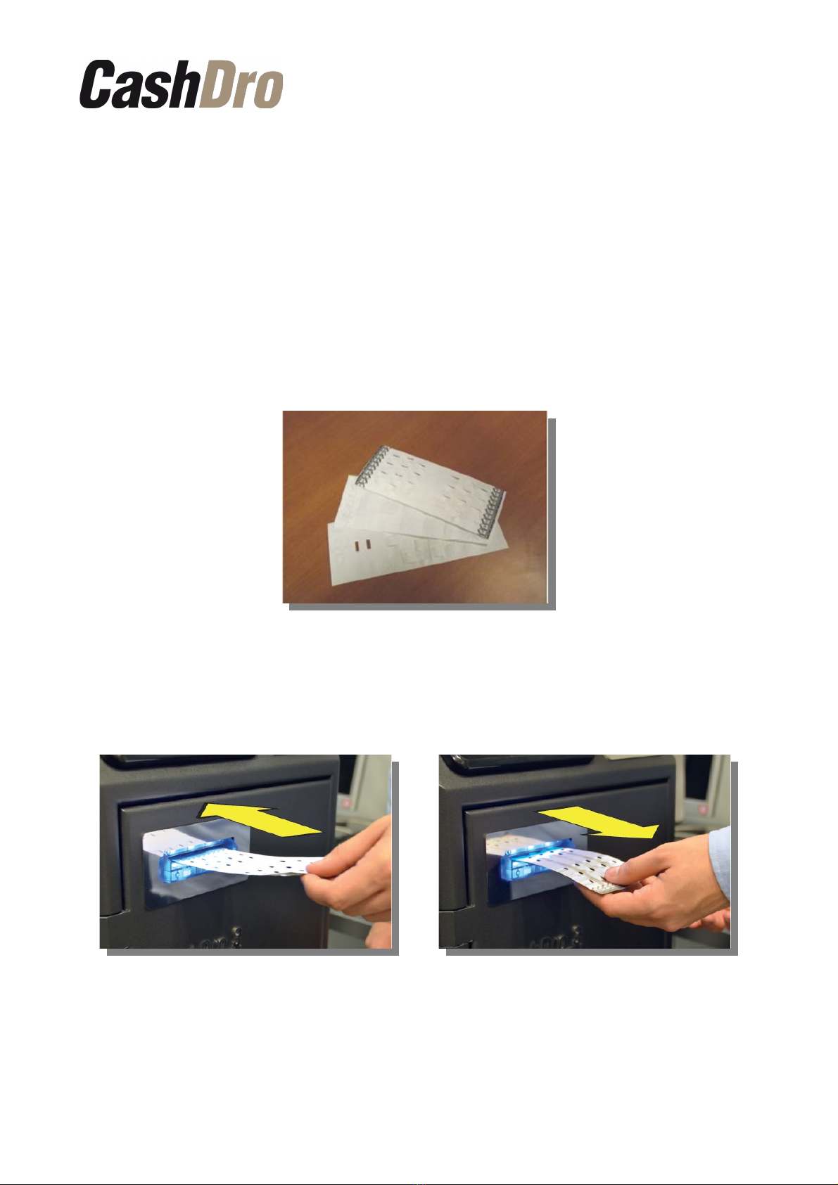
Use specific cleaning cards for Bill Validator, his flexibility produces the desired cleaning
effect by increasing the pressure applied to the internal components when passing through
the mechanism. It also acts in the cavities of the surface cleaning the embedded sensors.
Moreover, the anterior and posterior surfaces of the optical rounded lenses obtained
effective cleaning. If you use a flat cleaning card not reach the sensor holes and in the
best case, only have contact with the convex rounded tip of the optical lens. When
introduced and dispensed the cleaning card by the mechanism, being cleaning all
surfaces.
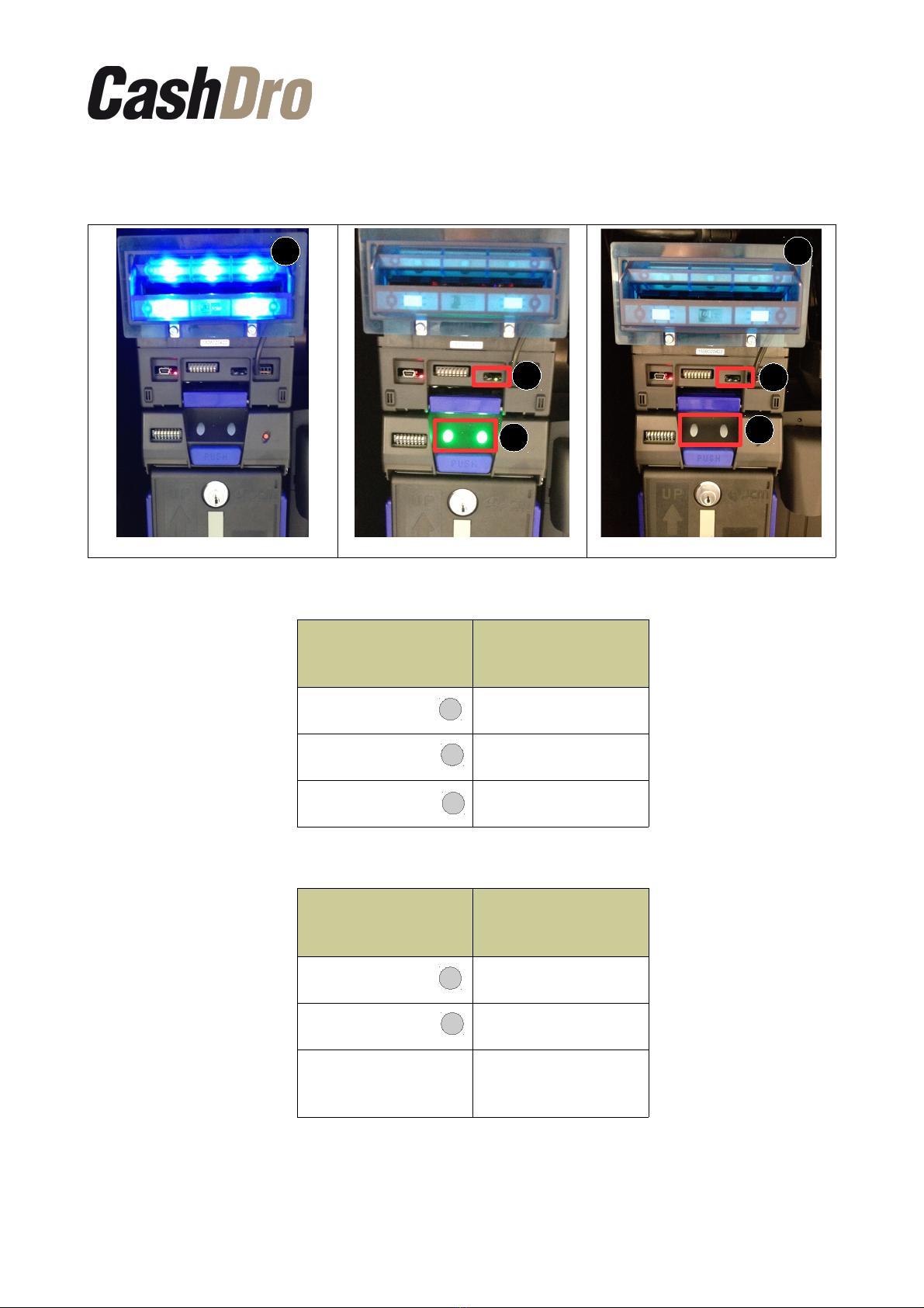
The cleaning process of Bill Device must be realized with CashDro3 on and in the charge
screen. You must insert the cleaning card when the front of the validator is in blue, that is
to say, active. When entering clean the sensors and the alignment mechanism and does it
again on departure.
After entering the cleaning card, it will be ejected automatically.
The cleaning process should be performed several times to verify that the cleaning card
has been impregnated with all the dirt of Bill Validator.
Maintenance manual | 7

The cleaning card will be discarded when mostly are black or dry.
During the process is possible that the validator is not active in blue. Wait several
seconds until the cessation of moisture in the validator, restart CashDro and
continue the operation.
6.2.2 Chassis and recyclers
You must remove the recyclers set to verify that not exists any jam or object that prevents
proper operation. To do this, press the blue button on top of the recyclers set and stretch
out.
Check in the chassis that belt are properly positioned and sensors are not dirty or blocked.
Verify also the rear of the recyclers set.
Maintenance manual | 8

Due the cleaning card clean exclusively the validator, you need to review the indicated
sensors and review that not are dirty or obstructed.
Id. Type of sensor Id. Type of sensor
a RC2 End sensor LED k RC2 Full sensor LED
b RC1 End sensor LED l Lifter Home position Sensor LED
c Recycle Unit Sensor m Lifter Home position Sensor PT
d RC1 Full Sensor PT n RC2 End sensor PT
eDouble Notes Detection Sensor
LED o RC2 Full sensor PT
fDouble Notes Detection Sensor
PT p Transport sensor 2 Prism
g RC1 End Sensor PT q Lifter Home position Sensor Prism
h Transport sensor 1 r Recycle Unit Sensor Prism
i RC1 full sensor LED s Transport sensor 1 Prism
j Transport sensor 2
Maintenance manual | 9

6.3 Interval
The following table is a guideline for the periods when maintenance should be employed
based on the average number of bills inserted into the unit per day (2 h):
Bill per Day (BPD) Interval
≤ 325 3 Months
≤ 500 2 Months
≤ 750 1 Month
Period (whichever is first) 30.000 o 3 months
Service time (per unit) 7-10min
Maintenance manual | 10

Bill Device CD3
Code:
ENCD3BD001
Version:
1.01
Date:
2017/09/22
www.cashdro.com
Table of contents
Popular Cash Counter manuals by other brands

Alberici
Alberici HopperOne S11 Operator's manual

Kolibri
Kolibri Rook user manual

DS Produkte
DS Produkte AP2110 instructions

MEI
MEI Cashflow SC Series Operation & maintenance manual

Wincor Nixdorf
Wincor Nixdorf iCASH 15 Cleaning Instruction Guide

GeoVision
GeoVision GV-3D People Counter V2 quick start guide

ratiotec
ratiotec rapidcount X 300 P Calibration guide

Green
Green GPM-312-A instruction manual

MC Electronics
MC Electronics AREA CONTROL MCK 3000 Use and Assembly Instructions

Nautilus Hyosung
Nautilus Hyosung Monimax 5300CE installation manual

Eaton
Eaton 57600-401 Installation and operation manual

Triton
Triton RL1600 Quick reference guide